
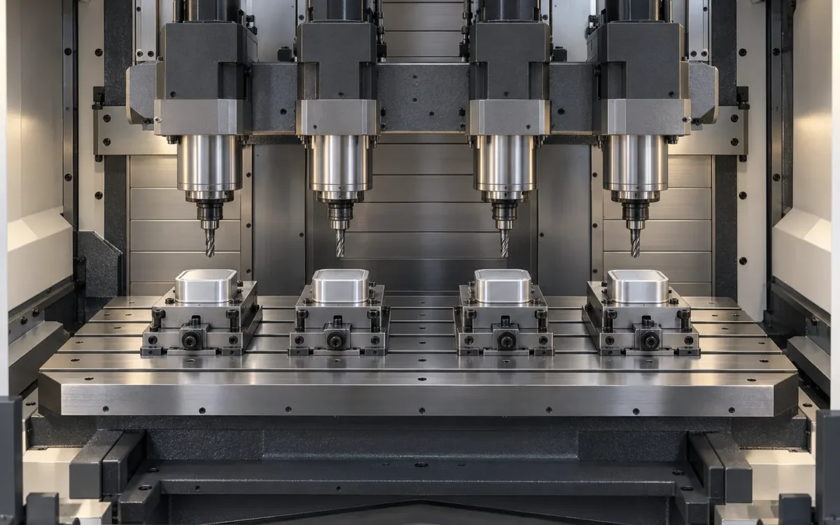
다주축 CNC: 병렬 가공의 생산성·정밀도와 부품 원가 설계
다주축 CNC · GPN TECHNICAL INSIGHT
다주축 CNC: 병렬 가공의 생산성·정밀도와 부품 원가 설계
다주축 CNC는 여러 개의 주축이 각각의 공작물을 동시에 절삭하도록 구성하는 생산 시스템입니다. 핵심은 주축을 늘리는 데 그치지 않고, 공구·지그·제어·소재 교환을 하나의 사이클로 설계해 시간당 양품 생산량을 높이는 데 있습니다.
워치 케이스와 같은 소형 금속 외장, 반복 수요가 있는 하우징과 정밀 부품은 한 대의 설비에서 여러 개를 병렬로 가공하는 방식을 검토할 수 있습니다. 동일한 형상과 공정 순서를 반복하는 시간이 길수록 병렬화의 여지가 커집니다. 반면 소재 교환·검사·공구 관리가 가공을 따라가지 못하면 주축 수만큼 생산량이 늘어나지 않습니다.
4주축의 성능은 단주축 대비 생산량, 8주축의 적합성은 전체 공정의 수용 능력으로 평가해야 합니다. 가공 속도가 빨라지는 효과와 여러 부품이 동시에 완성되는 효과를 구분하고, 같은 품질 기준을 만족하는 양품 수량으로 비교하는 것이 출발점입니다.
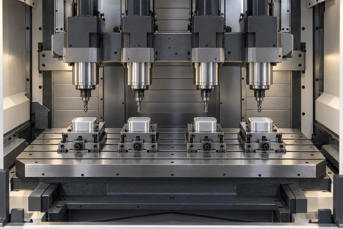
1. 다주축 CNC의 원리: 순차 절삭을 병렬 절삭으로 전환
일반적인 단주축 머시닝센터에서는 테이블 위에 공작물을 여러 개 배열해도 하나의 공구가 위치를 옮겨 가며 절삭합니다. 같은 공구로 여러 부품을 연속 가공하면 공구 교환을 묶고 소재 준비 시간을 줄일 수 있지만, 실제 절삭은 한 번에 한 위치에서 진행됩니다.
다주축 CNC는 이 절삭 지점을 여러 개로 구성합니다. 예를 들어 같은 공구를 장착한 4개의 주축과 이에 대응하는 4개의 지그가 있다면, 동일한 포켓·홀·외곽 가공을 네 부품에서 동시에 수행할 수 있습니다. 각 부품의 절삭 조건을 무리하게 높이지 않고도 한 사이클의 완성 수량을 늘리는 방식입니다.
| 구성 | 동시에 진행되는 작업 | 생산성 검토의 초점 |
|---|---|---|
| 단주축·다수 지그 | 한 공구가 여러 부품을 순차적으로 가공합니다. | 공구 교환 묶음, 이동 경로, 소재 준비와 가공의 중첩을 검토합니다. |
| 다주축·병렬 가공 | 복수 공구가 대응하는 부품을 동시에 가공합니다. | 주축 간 공정 균형, 지그 피치, 동시 가공 정밀도와 양품 수량을 검토합니다. |
| 4축·5축 제어 | 이송·회전축을 조합해 공구와 부품의 자세를 제어합니다. | 접근 방향과 재고정 횟수, 복잡한 형상의 가공 가능성을 검토합니다. |
주축 수와 제어축 수는 서로 다른 사양입니다. 4주축은 절삭용 주축이 네 개라는 뜻이며, 4축 가공은 이송·회전의 제어 자유도를 의미합니다. 4주축 설비에 5축 가공 기능을 결합할 수도 있으므로, 설비 비교에서는 두 항목을 각각 확인해야 합니다.
또한 여러 공구가 한 부품의 여러 위치를 동시에 가공하는 다축 헤드, 공작물을 회전시키며 공정을 나누는 다주축 자동선반은 병렬 생산이라는 공통점이 있어도 구조가 다릅니다. 소형 케이스와 하우징의 반복 밀링에서는 공구 주축과 공작물 위치의 대응 관계부터 정의해야 합니다.
2. 공통 이송 구조와 독립 제어 구조의 차이
공통 이송 구조: 동일 형상과 일정한 지그 간격
여러 주축이 공통 이송계를 사용하는 구조에서는 같은 이동이 각 절삭 지점에 전달됩니다. 따라서 주축 중심 간격과 지그의 부품 기준 간격이 맞아야 하며, 부품마다 가공할 위치와 방향도 동일하게 재현되어야 합니다. 공구 직경과 길이의 차이, 소재 여유량의 편차까지 고려한 공정 설계가 필요합니다.
공통 X·Y 이송만으로 모든 위치를 움직이는 구성에서는 부품별 평면 위치 오차를 동시에 서로 다르게 보정할 수 없습니다. 제어기에 보정값을 입력할 수 있다는 사실과 실제 기구가 개별 움직임을 만들 수 있다는 사실을 구분해야 합니다. 독립 보정이 가능한 축과 범위는 기계 구조에서 결정됩니다.
독립 Z축과 다채널 제어: 보정 범위와 유연성
주축별 독립 Z축은 공구 길이와 가공 깊이 차이에 대응할 여지를 줍니다. 그러나 Z축이 독립적이라는 이유만으로 각 주축이 서로 다른 평면 윤곽을 자유롭게 가공할 수 있는 것은 아닙니다. 다른 형상과 경로를 동시에 처리하려면 필요한 이송축과 제어 채널이 실제로 독립되어 있어야 합니다.
다채널 CNC에서는 각 채널의 가공 프로그램과 공유 자원 사용 순서를 조정합니다. 공구 교환, 테이블 인덱싱, 소재 교환처럼 서로 간섭할 수 있는 단계에는 동기화 지점과 완료 확인을 둡니다. 가장 늦게 끝나는 채널을 기다리는 시간이 생기므로, 제어의 독립성과 공정의 균형을 함께 검토해야 합니다.
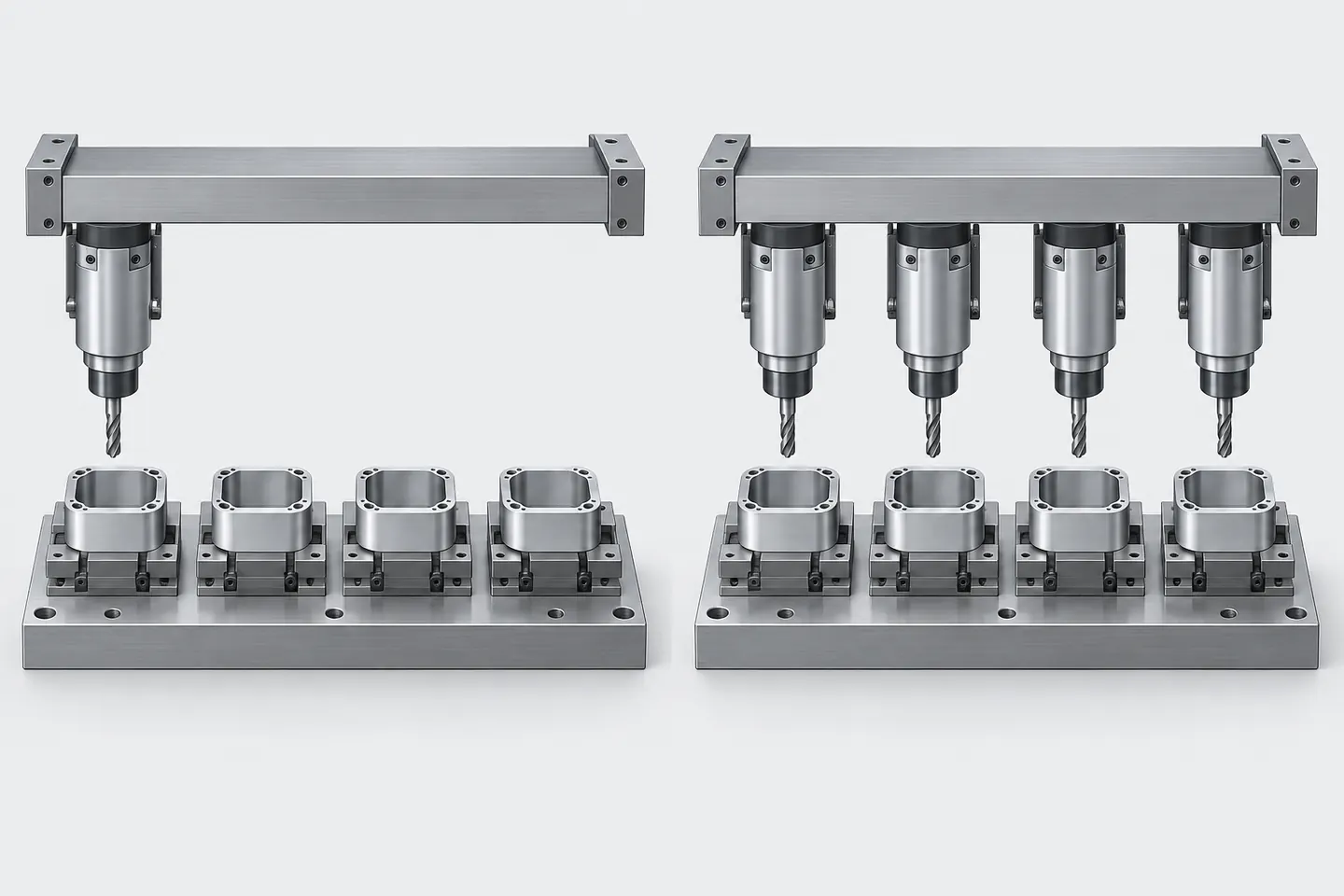
4주축에서 8주축으로 확장할 때의 설계 조건
주축을 늘리면 가공 영역과 지그 피치뿐 아니라 공통 구조의 강성, 이송부 질량, 전원·냉각·칩 처리 용량도 달라집니다. 동시 절삭 시 구조에 작용하는 힘과 모멘트, 일부 위치만 가공할 때의 비대칭 하중을 확인해야 합니다. 기존 단주축 기계에 주축 모터만 추가하는 방식으로 동일한 정밀도를 확보하기는 어렵습니다.
8주축 구성은 전용 설비의 검토 대상이 될 수 있지만, 주축 수만으로 적용 범위나 생산성을 확정할 수 없습니다. 한 번에 준비해야 하는 소재 수, 공구 세트 수, 검사 시간, 고장 시 정지 범위를 함께 설계해야 합니다. 8개라는 숫자도 다주축 기술 전체의 보편적인 상한을 뜻하지 않습니다.
3. 다주축 CNC 생산성: 4주축이 4배가 되지 않는 이유
생산성은 같은 시간 동안 완성하는 수량으로 계산합니다. 한 부품에 필요한 절삭 경로가 같더라도 소재 장착·해제, 공구 교환, 측정, 테이블 이동과 채널 대기까지 포함하면 전체 사이클이 달라집니다. 비교 대상인 단주축 설비에도 다수 지그와 공구 교환 최적화를 적용한 상태에서 평가해야 차이를 공정하게 판단할 수 있습니다.
완성 수량이 다른 사이클의 비교
생산성 배율 S = (Nm / Tm) ÷ (Nb / Tb)
N은 비교 공정까지 완료한 부품 수, T는 해당 배치 사이클 시간입니다. b는 기준 설비, m은 다주축 설비를 뜻합니다. 기준이 1개씩 가공하는 단주축이면 S = Nm × Tb / Tm으로 계산합니다.
4주축의 사이클 비교 예시
다음은 생산성의 구조를 설명하기 위한 가상 계산입니다. 특정 설비의 시생산 결과나 보장 성능을 뜻하지 않습니다. 동일한 가공 범위의 부품을 단주축에서 1개, 4주축에서 4개씩 완성한다고 가정합니다.
| 시간 구성 | 단주축·1개 배치 | 4주축·4개 배치 |
|---|---|---|
| 절삭 구간 | 100초입니다. | 동일 절삭을 병렬로 수행하는 100초입니다. |
| 소재·공구 교환 및 측정 | 20초입니다. | 배치 전체에서 50초입니다. |
| 추가 동기화·대기 | 0초로 가정합니다. | 20초로 가정합니다. |
| 총 배치 사이클 | 120초입니다. | 170초입니다. |
| 가동 중 시간당 완성 수량 | 3,600 ÷ 120 = 30개입니다. | 4 × 3,600 ÷ 170 ≈ 84.71개입니다. |
이 조건의 생산성 배율은 4 × 120 ÷ 170 ≈ 2.82배입니다. 한 부품을 깎는 절삭 시간이 4분의 1로 줄어든 것이 아니라, 병렬 절삭의 이득 일부를 늘어난 부대 시간이 차감한 결과입니다. 2.82배는 이 가정에서 산출한 값이며, 실제 설비의 생산성은 동일 공정 범위에서 측정한 배치 시간과 완성 수량으로 확인해야 합니다.
정지와 불량을 포함한 시간당 양품 수량
Qgood = 3,600 × N × A × Y ÷ T
T는 가동 중 배치 사이클(초), A는 비교 시간 중 실제 가동한 비율, Y는 완성품 중 양품 비율입니다. T가 이미 정지 시간을 포함한 실측 평균이면 같은 손실을 A에 다시 반영하지 않습니다.
위 예시에서 단주축의 A = 0.85, Y = 0.99, 4주축의 A = 0.80, Y = 0.985를 가정하면 시간당 양품은 각각 약 25.25개와 66.75개입니다. 양품 기준 배율은 약 2.64배로 낮아집니다. 여기에 실제 발주량이 부족해 주축 위치를 비우거나 설비를 가동하지 못하는 시간까지 생기면 연간 생산량은 별도로 줄어듭니다.
공구 파손이나 소재 공급 지연이 공통 사이클을 멈추는 구조에서는 한 위치의 이상이 전체 배치에 영향을 줍니다. 설비 선정 단계에서 절삭 시간뿐 아니라 정지 빈도·복구 시간·장착 시간을 넣은 시뮬레이션이 필요한 이유입니다.
4. 다주축 CNC 사이클 설계: 상하차·세척·공구 교환의 통합
병렬 절삭의 이득은 절삭 전후의 동작을 어떻게 배치하느냐에 따라 달라집니다. 네 개를 동시에 가공해도 네 부품의 반출·소재 장착·착좌 확인이 길어지면 다음 절삭의 시작이 늦어집니다. 따라서 설비를 구성할 때에는 가공 영역과 자동화 장치, 유체 공급, 공구 교환의 동작 순서를 함께 설계해야 합니다.
작업문 반대편의 회전 구동부와 상하차 접근 공간
회전·틸트 구동부를 작업문 반대편에 배치하는 것은 전면의 소재 교환 공간을 확보하기 위한 설계 방안입니다. 구동부와 지지 구조가 그리퍼의 진입 경로를 차지하지 않도록 구성하면, 제품 반출과 소재 투입의 불필요한 우회 동작을 줄일 여지가 있습니다. 작업문 크기만 넓히는 것과 달리 지그·구동부·로봇의 상대 배치를 함께 검토하는 접근입니다.
여기서 DD(Direct Drive) 모터는 회전 테이블이나 틸팅 모듈의 직접 구동을 뜻하며, 절삭 공구를 회전시키는 주축 모터와 구분합니다. 감속 기구를 줄이는 구성은 가능하지만 실제 회전 정확도와 절삭 중 자세 유지 성능은 베어링·엔코더·구조 강성·열변위·클램프 조건까지 영향을 받습니다. DD 채택만으로 상하차 시간이 짧아지거나 정밀도가 보장되는 것은 아닙니다.
간섭 검토는 그리퍼만 통과시키는 것으로 끝나지 않습니다. 소재를 잡은 상태의 이동 궤적, 완성품을 꺼내며 회전하는 범위, 클램프 돌출부, 회전축에 연결된 배관과 케이블의 움직임을 포함합니다. 정상 운전뿐 아니라 공구 교체, 지그 정비, 정지 후 부품 회수에 필요한 접근 공간도 확보해야 합니다.
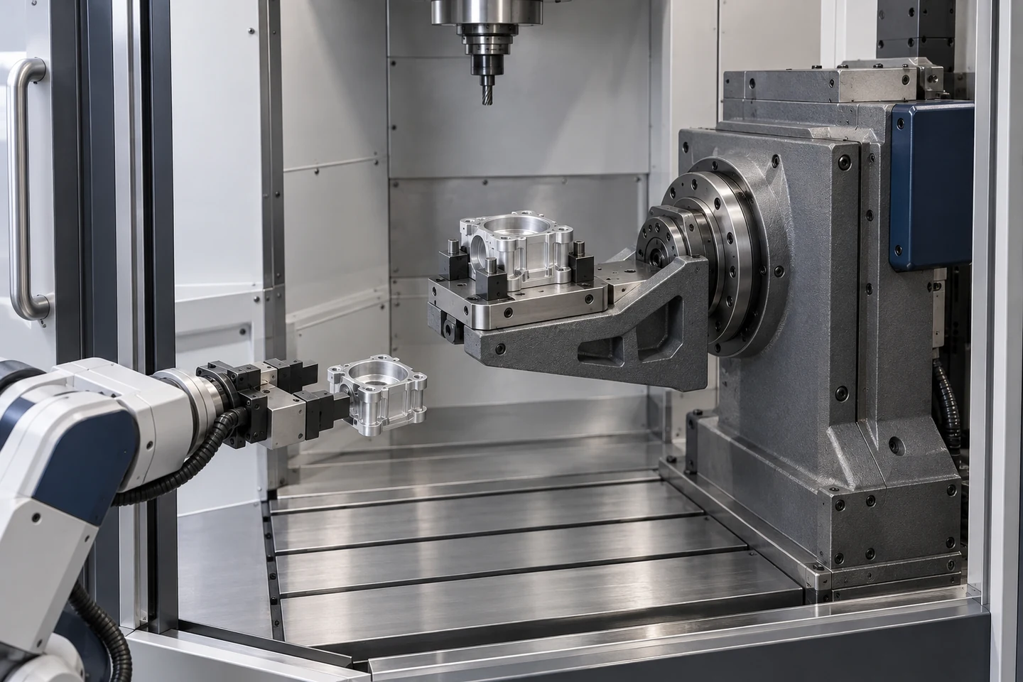
소재 준비의 중첩과 가공 시작 조건
교환식 팔레트나 분리된 준비 영역은 가공 중 다음 배치의 소재를 준비하는 데 사용할 수 있습니다. 다만 소재를 교환하기 위한 팔레트 선회와 절삭 중 부품 자세를 제어하는 회전축은 역할이 다릅니다. 팔레트가 회전한다는 사실만으로 동시 5축 보간이나 주축별 독립 자세 제어가 가능한 것으로 판단하지 않습니다.
다중 그리퍼는 이동 횟수를 줄일 수 있지만, 소재 중량·위치 편차와 파지 확인 항목도 늘어납니다. 반출, 착좌면의 칩 제거, 소재 투입, 클램프 작동, 착좌 확인을 하나의 순서로 정의하고 각 단계의 완료 조건을 둡니다. 로봇의 이동 완료 신호와 소재의 올바른 고정은 서로 다른 확인 항목입니다.
일부 준비 동작을 절삭과 겹칠 수 있어도 모든 시간이 사라지는 것은 아닙니다. 준비가 늦게 끝나는 구간, 문 개폐와 안전 확인, 마지막 클램프 완료 이후의 대기를 구분해 기록합니다. 가공과 준비 시간이 중첩되는 설비에서는 각각의 시간을 단순 합산하지 않고 실제 시간선에서 다음 절삭까지 남는 구간을 계산합니다.
냉각수·에어 공용 노즐과 착좌면 관리
같은 노즐에서 냉각수와 에어 블로를 전환하는 구성은 절삭 중 공급과 가공 후 칩 제거를 한 위치에서 수행하도록 설계하는 방식입니다. 솔레노이드 밸브로 유체를 전환하면 별도 노즐의 설치 공간을 줄일 수 있습니다. 그러나 밸브의 작동 신호가 곧 절삭점의 정상 공급을 의미하지는 않습니다.
공용 경로에서는 냉각수의 공기 배관 유입과 공기의 냉각수 계통 역류를 방지해야 합니다. 전환 순서, 잔류 압력과 액체의 배출, 역류 방지 장치, 배관의 사용 압력을 함께 검토합니다. 여러 주축에 동시에 공급할 때는 공통 펌프 압력 외에 각 분기의 유량과 노즐 방향, 막힘 여부도 확인해야 합니다.
착좌면에 남은 칩은 다음 소재의 높이와 자세를 바꿀 수 있습니다. 분사 후에는 칩이 지그 포켓이나 인접 부품으로 다시 이동하지 않는지 확인하고, 배출·회수·여과 경로를 확보합니다. 에어 블로에는 비산 입자와 미스트의 밀폐·회수 조건도 필요합니다. 기내 칩 제거가 가능하다는 이유만으로 최종 세척이나 청정도 검사를 생략하지 않습니다.
공구 매거진 배정과 절삭 재개 시간
공구 교환은 공구를 바꾸는 기구 동작과 다음 공구를 교환 위치에 준비하는 동작으로 나눠 볼 수 있습니다. 매거진 슬롯을 실제 사용 공구 수보다 여유 있게 확보하고 홀수·짝수 포켓을 구분하는 배정 규칙을 검토할 수 있습니다. 예를 들어 44슬롯에 최대 22개 공구를 운용하는 구성은 포켓 배치와 반환 위치를 설계할 여지가 있지만, 슬롯 수만으로 교환시간의 균일성을 보장하지는 않습니다.
다음 공구를 현재 절삭 중 미리 준비하면 매거진 탐색 대기를 줄일 수 있습니다. 반면 현재 절삭 구간이 짧거나 선행 준비가 중단되면 공구 교환 시점에 대기가 남습니다. 공구 크기에 따른 인접 포켓 제한, 최장 인덱싱 경로, 반환 포켓, 예비 공구 전환과 주축별 교환 순서를 실제 가공 프로그램으로 확인해야 합니다.
| 구분 | 확인하는 시간 | 비교 시 필요한 조건 |
|---|---|---|
| Tool-to-Tool, T-T | 정해진 시작·종료 조건에서 공구 교환 동작에 걸리는 시간입니다. | 공구의 무게·크기, 매거진 위치와 측정 정의를 맞춥니다. |
| Chip-to-Chip, C-C | 앞선 절삭이 끝난 뒤 다음 공구로 절삭을 다시 시작하기까지의 구간입니다. | 이탈·접근 거리, 주축 정지·재가속, 공구 준비와 위치결정 조건을 확인합니다. |
| 전체 배치 사이클 | 같은 공정 범위의 부품을 한 배치 완성하는 데 걸리는 시간입니다. | 모든 주축의 완료, 공통 교환 장치와 소재 준비의 대기를 포함합니다. |
공통 교환 장치의 대기와 주축별 공구 수명
빠른 T-T 사양이 그대로 짧은 전체 사이클을 뜻하지는 않습니다. 여러 동작이 겹치는 제어에서는 겹친 시간을 중복해서 더하지 않고, 가장 늦게 완료되는 필수 동작을 확인합니다. 주축별 매거진이 독립적인지, 교환 장치나 이동축을 공유하는지에 따라서도 대기 구조가 달라집니다.
같은 공구를 사용하더라도 소재 여유량과 냉각 공급 차이로 마모가 달라질 수 있습니다. 주축별 길이·직경·사용 이력을 관리하고 필요 공정에는 파손 검출을 적용합니다. 묶음 교환은 정지 횟수를 줄일 수 있지만 남은 공구 수명을 덜 사용할 수 있으므로, 개별 교환과의 경제성은 공구비와 정지 손실을 합쳐 비교합니다.
기내 버 제거와 일반 세척의 구분
가공 직후 같은 고정 상태에서 버 제거를 수행하면 부품을 다시 운반하고 위치 결정하는 단계를 줄일 수 있습니다. 도면 기준과 연결된 좌표에서 노즐을 특정 홀 출구나 모서리에 접근시키는 방식은 공정 통합의 검토 대상입니다. 다만 떨어져 있는 칩을 씻어내는 세척과 모재에 붙은 버를 제거하는 디버링은 요구 결과가 다릅니다.
유체 분사로 버를 제거하려면 재질, 버 뿌리의 두께와 형상, 노즐 직경·거리·각도, 압력·유량과 처리 시간을 함께 정해야 합니다. 펄스 방식을 채택하는 경우에는 분사의 반복 조건도 검증 대상입니다. 일반 절삭유 공급에 노즐을 추가했다는 사실만으로 고압 또는 펄스 디버링 성능이 성립하지는 않습니다.
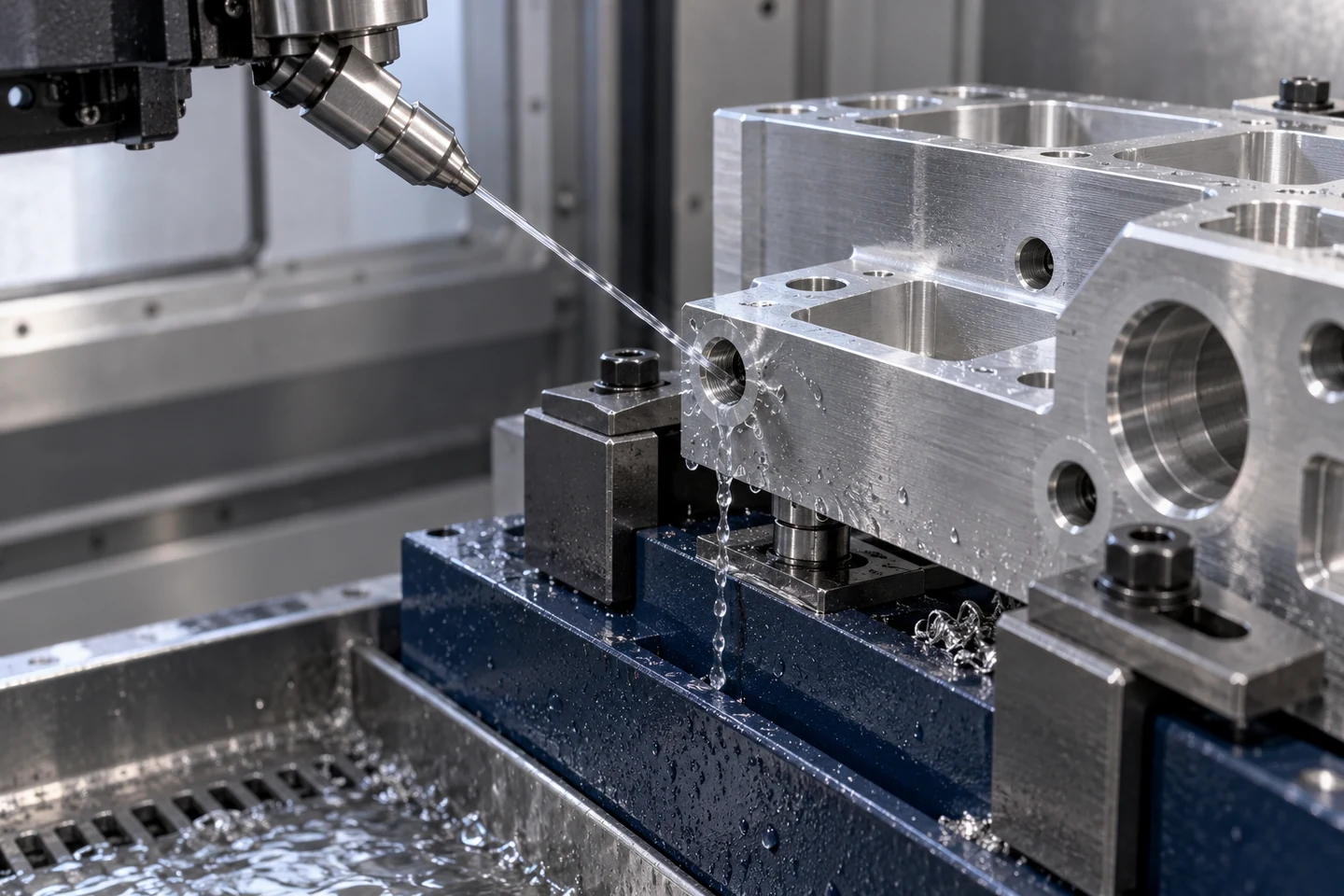
처리 후에는 잔류 버, 요구 모서리 형상, 박육부 변형, 표면 손상과 잔류 입자를 확인합니다. 제거한 입자가 다른 홀이나 포켓에 남지 않도록 회수·여과·배출 조건도 연결합니다. 기내 장치의 배관·씰·노출부는 선정한 유체 조건에 적합해야 하며, 부품별 시험 없이 압력이나 제거 가능한 버 크기를 일률적으로 정하지 않습니다.
버 제거가 절삭과 겹치지 않으면 그 시간은 CNC 점유 시간에 더해집니다. 외부 이송·재고정 시간의 절감과 기내 처리로 늘어난 시간을 함께 비교하고, 최종 양품 생산량이 개선되는 범위에서 공정을 통합해야 합니다.
자동 반송과 생산 이력의 연결
자동 반송 장치는 소재와 완성품의 이동을 담당하고, 생산관리 시스템은 작업 지시와 생산·품질 이력을 연결합니다. 어느 쪽도 절삭 사이클의 병목을 자동으로 없애지는 않습니다. 소재 부족, 반출 지연과 검사 대기 시 확보할 버퍼 용량, 정지 범위와 재시작 조건을 정해야 합니다.
부품 이력에는 배치뿐 아니라 주축 번호, 지그 위치, 공구 상태와 검사 결과를 연결하는 것이 유용합니다. 작업 지시 번호가 같더라도 한 위치에서만 치수 편차가 생길 수 있기 때문입니다. 통신이 끊기거나 일부 부품만 재가공할 때 이력이 중복·누락되지 않도록 처리하고, 세척·버 제거·검사가 병렬 가공의 출력을 수용하는지도 확인합니다.
5. 다주축 CNC 정밀도: 반복 지그와 주축 간 편차 관리
다주축의 품질 목표는 하나의 정밀한 부품을 만드는 데서 끝나지 않습니다. 같은 배치의 모든 위치에서 도면을 만족하고, 시간과 공구 사용량이 달라져도 그 상태를 유지해야 합니다. 평균값이 양호하더라도 특정 주축에서만 치수가 벗어나는 상황을 구분할 수 있어야 합니다.
피치와 기준면, 고정 후 변형의 연결
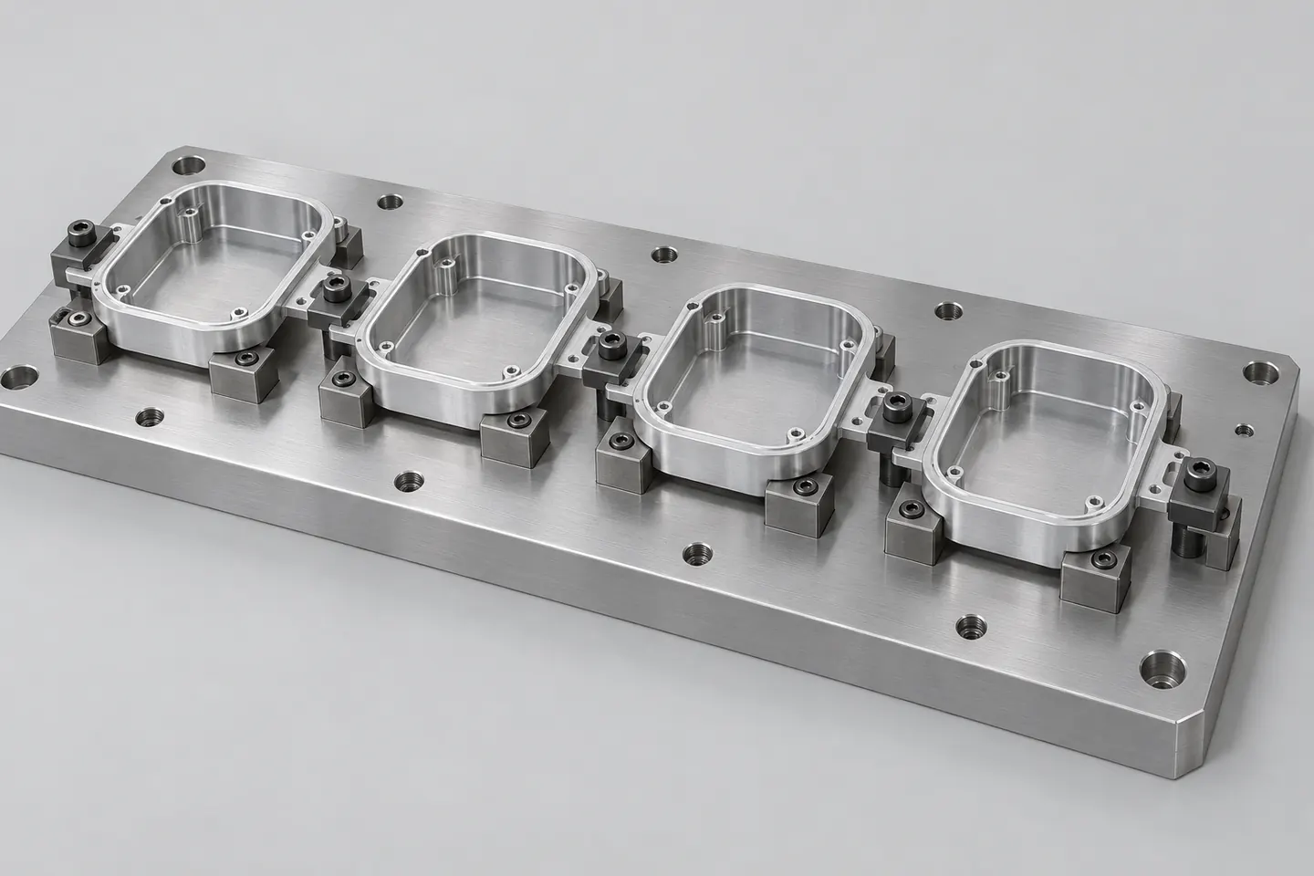
반복 지그는 부품의 기능 기준을 동일한 방향과 높이로 재현하도록 설계합니다. 주축 피치에 맞춰 부품을 배열하는 것과 각 부품을 정확히 위치 결정하는 것은 별도의 과제입니다. 지그 포켓의 편차, 교체형 부품의 마모, 착좌면의 칩과 소재 형상 편차를 각각 확인합니다.
얇은 케이스는 고정 중에는 치수가 맞아도 클램프를 풀면 변형이 나타날 수 있습니다. 지지 위치와 고정력을 절삭 하중에 맞추고, 필요하면 가공용 여유부를 활용합니다. 가공 중 측정값과 고정 해제·세척 후 측정값을 비교해야 조립 상태에서의 품질을 판단할 수 있습니다.
열변위와 동시 절삭 진동
주축 베어링·모터·이송계와 절삭 과정에서 발생하는 열은 공구와 공작물 사이의 상대 위치를 바꿀 수 있습니다. 같은 프레임 안에서도 주축별 가동 이력과 냉각 조건이 다르면 변위가 동일하지 않을 수 있습니다. 초기 가동, 연속 가공, 정지 후 재가동 조건을 나눠 측정하고 보정이 가능한 축과 범위에서 대응합니다.
동시 절삭에서는 공통 프레임과 테이블을 통해 진동이 전달될 수 있습니다. 단주축에서 안정적이었던 절삭 조건을 그대로 복제하기보다, 실제 동시 가공 상태의 표면 무늬·치수·공구 상태를 평가해야 합니다. 여러 공구가 한 공작물을 가공하는 연구의 안정성 결과를 서로 다른 부품을 가공하는 설비에 수치 그대로 적용하지 않습니다.
열 영향 평가와 가공 시험편을 통한 절삭 정확도 검증은 각각 ISO 230-3과 ISO 10791-7 같은 시험 체계를 참고할 수 있습니다. 적용 가능한 기계 구성과 시험 범위를 확인하고, 실제 부품·지그·공구의 양산 시험을 추가합니다. 표준 시험편 합격과 특정 제품의 지속적인 양품 생산은 구분해 평가합니다.
주축 번호와 지그 위치를 남기는 품질 이력
측정 결과에는 주축 번호, 지그 위치, 공구 사용량과 가공 시간을 연결합니다. 위치별 평균 차이와 시간에 따른 변화를 따로 보면 공통 열변위와 특정 지그·공구 문제를 구분하는 데 도움이 됩니다. 전체 데이터를 하나로 합친 평균이나 산포만으로 공정 상태를 판단하지 않습니다.
6. 소형 외장과 로봇 부품에 적용하는 조건
소형 금속 외장은 동일한 포켓·홀·외곽 가공이 반복되는 제품군을 묶어 검토할 수 있습니다. 모델마다 형상이 달라도 소재, 기준면, 공구 구성과 가공 순서가 유사하면 공통 설비에 교체형 지그와 프로그램을 적용하는 방안을 검토합니다. 다만 공통 이송 구조에서 서로 다른 형상의 동시 가공이 가능한지는 별도로 확인해야 합니다.
로봇 부품에서는 관절 하우징, 베어링 지지부, 체결 플랜지, 브래킷처럼 반복 수요가 있는 절삭 부품이 검토 대상입니다. 가공할 수 있는 형상보다 먼저 생산 수량·재질·공구 접근 방향·요구 공차의 공통성을 확인합니다. 다품종 소량과 잦은 설계 변경이 중심이라면 더 적은 주축 수나 독립 설비가 유리할 수도 있습니다.
| 대상 형상 | 병렬화 검토 요소 | 완성품에서 확인할 기능 |
|---|---|---|
| 소형 케이스·커버 | 반복되는 포켓·홀, 박육부 지지, 후공정과의 연결을 검토합니다. | 해제 후 변형, 조립면, 외관과 모서리 상태를 확인합니다. |
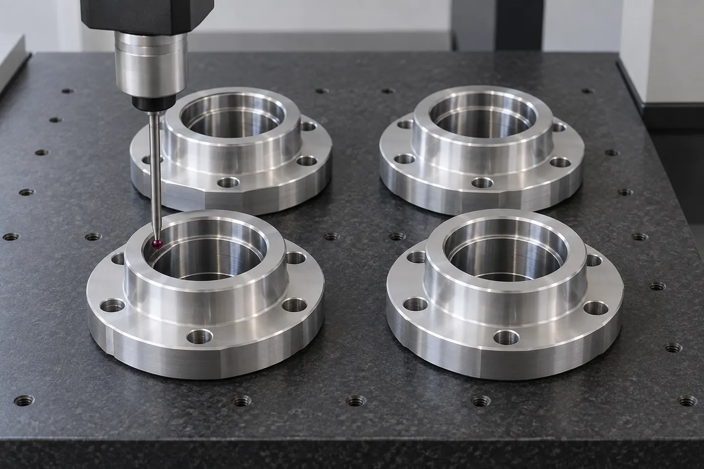
| 관절·베어링 하우징 | 보어와 기준면의 공정 순서, 정삭 공구, 재고정 필요성을 검토합니다. | 도면에 지정된 보어 크기·원통도·축 관계·면의 자세를 확인합니다. |
| 플랜지·브래킷 | 체결홀 배열, 평면 가공, 공구 공통성과 부품 방향을 검토합니다. | 홀 위치와 조립 간섭, 기준면 관계를 확인합니다. |
관절 조립체의 정밀도는 절삭 부품 외에도 베어링·구동계·체결과 조립 조건에 영향을 받습니다. 특정 하우징을 병렬 가공할 수 있다는 사실을 로봇 전체의 성능이나 원가 절감으로 바로 확대하지 않습니다. 열처리·연삭·표면처리 등이 필요한 부품은 해당 후공정까지 포함해 생산 체계를 구성해야 합니다.
국내 생산 비중 확대는 공급 체계의 목표이며, 부품 원가 절감률과 같은 지표가 아닙니다. 국내로 옮길 부품군과 유지할 외주 공정을 구분하고, 동일한 품질·납기·물량 조건에서 제조 원가를 비교해야 합니다.
7. 생산성 향상과 부품 원가 절감을 연결하는 계산
주축 수가 아닌 양품당 비용
다주축 CNC는 기계 프레임·설치 면적·자동화 자원을 여러 절삭 지점이 공유할 수 있습니다. 동시에 주축, 공구 세트, 냉각 설비와 유지보수 비용도 증가할 수 있습니다. 따라서 설비 가격을 주축 수로 나누거나 생산성 배율의 역수를 제품 원가에 바로 적용해서는 안 됩니다.
양품당 가공 셀 비용 = 시간당 셀 비용 ÷ 시간당 양품 수량
시간당 셀 비용에는 정한 비교 범위의 설비·인력·유지보수·에너지 비용을 포함합니다. 연간 고정비를 시간당 비용으로 바꿀 때에는 실제 이용 가능한 시간을 사용하며, 유휴 시간을 별도로 반영했다면 가동률에서 중복 차감하지 않습니다.
전체 부품 원가는 여기에 소재, 공구 소모, 세척·검사·후처리, 물류 및 불량 손실을 항목별로 더해 계산합니다. 같은 공구비나 인건비를 셀 비용과 별도 항목에 중복 반영하지 않도록 원가 범위를 먼저 정해야 합니다.
원가 지수 100을 사용하는 가상 비교
기준 부품 원가를 100으로 두고, 그중 40은 병렬화 후에도 동일한 비용, 60은 대상 가공 셀의 시간에 따라 달라지는 비용이라고 가정합니다. 양품 생산량이 3배가 되고 시간당 셀 비용이 같으면 총원가는 40 + 60 ÷ 3 = 60이 되어 40% 감소합니다.
그러나 다주축 셀의 시간당 비용이 1.5배라면 40 + 60 × 1.5 ÷ 3 = 70입니다. 생산성이 3배여도 이 가정에서 전체 원가 절감률은 30%입니다. 두 계산은 원가 구조를 설명하는 예시이며 실제 공급 가격이나 절감률을 제시하는 견적이 아닙니다.
같은 단순 모형에서 시간당 비용 증가가 없고 생산성이 3배라면, 전체 원가를 50% 줄이려면 최소 75%의 비용이 해당 생산성 향상의 영향을 받아야 합니다. 소재·구매품·후공정 비중이 높으면 설비 투자만으로 목표를 달성하기 어려운 이유입니다.
물량·품종 전환·유지보수까지 포함한 설비 비교
전용 다주축 1대와 여러 대의 단주축 설비는 같은 생산 목표에서 비교합니다. 투자비 외에 필요한 작업 면적, 소재 공급과 검사 인력, 품종 전환 시간, 예상 정지와 복구 시간을 포함합니다. 단주축 여러 대는 물량 변화와 고장에 분산 대응할 여지가 있고, 다주축은 공통 자원의 활용을 높일 여지가 있습니다.
양품 1개당 에너지는 순간 소비전력만으로 판단하지 않고, 비교 기간의 총 사용 에너지를 양품 수량으로 나눠 확인합니다. 최종 투자 검토에서는 예상 수요가 낮아지는 경우, 공구비가 증가하는 경우, 주요 모듈의 정지 시간이 길어지는 경우도 함께 계산해야 합니다.
8. 다주축 CNC 도입을 위한 공정 검증 순서
설비 구성을 확정하기 전에는 부품군과 현재 공정을 먼저 분석해야 합니다. 절삭 시간이 긴 공정을 찾는 것만으로는 부족합니다. 병렬로 처리할 수 있는 공정과 순차 처리해야 하는 공정, 공통 자원을 기다리는 구간을 구분해야 실제 개선 여지가 드러납니다.
- 기준 공정의 시간과 양품 수량 측정
소재 교환·공구 교환·절삭·측정·정지 시간을 구분합니다. 단주축의 다수 지그 운용과 공구 교환 묶음도 함께 평가합니다.
- 부품군과 병렬 가공 구조 결정
재질, 형상과 공구 경로의 공통성, 주축 피치, 필요한 독립축과 제어 채널을 정합니다. 2·4·8주축 등 후보 구성을 같은 생산 목표에서 비교합니다.
- 동시 절삭 상태의 시험 가공
모든 주축을 사용하는 조건에서 위치별 치수와 표면을 측정합니다. 초기·연속·재가동 상태, 공구 사용량과 지그 탈착의 영향을 함께 확인합니다.
- 전체 사이클과 이상 복구 검증
소재 준비·세척·검사까지 연결해 대기 시간을 확인합니다. 소재를 잡은 그리퍼의 전체 이동 궤적, 각 주축의 유체 공급, 최악 공구 전환 순서의 C-C 시간, 버 제거 후 잔류 입자를 검증합니다. 공구 파손·착좌 불량과 반송 지연 등 이상이 생겼을 때 정지 범위와 재시작 절차도 확인합니다.
- 양품 기준 원가와 생산 능력 확정
합의한 연속 운전 기간과 물량에서 양품 수량·공구비·정지 시간을 기록합니다. 실제 요구 품질과 수요 조건을 만족하는 구성을 선택합니다.
다주축 CNC 적용 검토에 필요한 자료
3D 형상과 공차 도면, 소재·열처리 상태, 월간·연간 수량, 현재 공정별 시간, 사용 공구, 주요 불량, 조립 기준과 후처리 요구를 함께 준비하면 검토 범위를 구체화할 수 있습니다. 설계 변경 주기와 품종별 물량 비중은 전용 설비와 유연한 설비를 비교하는 핵심 정보입니다.
공정 적용성은 CNC·MCT 정밀가공의 소재·형상·공차 검토와 연결합니다. 작은 홀처럼 공구·회전 상태·검사 조건의 영향이 큰 형상은 초미세홀 가공 기술자료의 세부 조건까지 함께 확인할 수 있습니다.
ENGLISH · TECHNICAL ARTICLE
Multi-spindle CNC: designing parallel machining for productivity, precision and component cost
Multi-spindle CNC uses several cutting spindles to machine corresponding workpieces simultaneously. Its value depends on integrating tooling, fixtures, control and material handling into a productive cycle. The practical measure is conforming parts per unit time, rather than spindle count alone.
Small metal cases and repeat-production housings are potential applications where similar features and operations recur. Parallel cutting can increase output without forcing a higher cutting rate on each part. However, handling, inspection and tool management must support the resulting batch output.
1. Sequential cutting and parallel cutting
A conventional single-spindle machining center may hold several parts on one table, but its cutter normally visits their locations sequentially. Grouping operations by tool can reduce tool changes and preparation losses. It does not create simultaneous cutting at several locations.
With four cutting spindles and four matching fixtures, equivalent pockets, holes and profiles can be machined on four parts together. Spindle count describes the number of cutting units; four-axis or five-axis machining describes controlled linear and rotary motion. A multi-spindle machine can also incorporate multi-axis capability, so both specifications need to be reviewed separately.
Multi-tool heads working on one part and multi-spindle automatic lathes are related production concepts but have different mechanical and process arrangements. For parallel milling of cases and housings, define the relationship between each tool spindle and its workpiece location before selecting the architecture.
2. Shared motion, independent axes and control channels
In a shared-motion architecture, the same feed movement acts at several cutting locations. Spindle spacing must match the spacing of functional workpiece datums, while orientation, stock allowance and tooling must suit the repeated path. Shared X and Y motion cannot simultaneously provide different planar corrections at different locations. Available correction depends on actual mechanical degrees of freedom, not simply on entering offsets in a controller.
Independent Z motion can accommodate differences in tool length or cutting depth. It does not by itself allow unrelated planar profiles to be machined simultaneously. Different simultaneous paths require the relevant independent feed axes and control channels.
Multichannel control coordinates programs and shared resources. Tool changes, table indexing and loading require appropriate synchronization and completion checks. Waiting for the slowest participating channel can become part of the cycle, so process balance matters alongside control flexibility.
Scaling from four to eight spindles
Increasing spindle count changes the working envelope, fixture pitch, moving mass, structural loading and requirements for power, cooling and chip removal. Evaluate combined forces and moments as well as asymmetric loading when only some locations are cutting. Adding motors to a single-spindle platform does not establish equivalent machining accuracy.
An eight-spindle arrangement can be considered in dedicated machine design, but its usefulness depends on material supply, tooling sets, inspection capacity and the extent of a stoppage. Eight is not a universal technological upper limit. The appropriate count follows from the complete production requirement.
3. Comparing cycle output instead of spindle count
For a defined and identical scope of completed operations, let N be completed parts per batch and T be batch cycle time. Productivity ratio S is (Nm/Tm)/(Nb/Tb), where b denotes the baseline and m the multi-spindle system. A fair baseline should include sensible single-spindle multi-fixture operation and tool-change grouping.
Consider an illustrative single-spindle cycle with 100 seconds of cutting and 20 seconds of handling, tool exchange and measurement: one part in 120 seconds. A hypothetical four-spindle cycle performs the equivalent cutting in parallel for 100 seconds, requires 50 seconds of auxiliary operations and adds 20 seconds of synchronization or waiting. It completes four parts in 170 seconds.
Running output is therefore 30 parts per hour for the baseline and approximately 84.71 for the four-spindle case. The ratio is 4 × 120/170, or approximately 2.82. The benefit comes from concurrent completion, not from reducing each part’s cutting time to one quarter. This 2.82 ratio is the calculated result of the hypothetical inputs above. It is neither a measured production result nor a guaranteed productivity rating for four-spindle machines.
Availability, quality and accepted output
For batch time T in seconds, accepted output per comparison hour is Qgood = 3,600NAY/T. Here A is the fraction of comparison time actually running, and Y is the accepted fraction of completed parts. If measured cycle time already includes downtime, do not deduct the same losses again through A.
Using hypothetical values A = 0.85 and Y = 0.99 for the baseline gives 25.25 accepted parts per hour. For the four-spindle case, A = 0.80 and Y = 0.985 give 66.75, a ratio of approximately 2.64. Annual output also depends on demand, occupied fixture positions and the scheduled operating period.
When a tool failure or loading delay stops a shared cycle, one location can affect the whole batch. Simulation using interruption frequency, recovery time and loading time is therefore useful when comparing architectures. A single ideal cutting-time comparison is insufficient.
4. Multi-spindle CNC cycle design: integrating handling, cleaning and tool changes
The benefit of parallel cutting depends on how operations before and after cutting are arranged. Even when four parts are machined together, lengthy unloading, blank loading and seating checks can delay the next cut. Machine layout therefore needs to integrate the machining area, automation equipment, fluid supply and tool-change sequence.
Rotary drives opposite the access door and clearance for loading
Rotary and tilting drives can be positioned opposite the access door to preserve front loading space. Keep the drives and their supports outside the gripper’s approach path. This can reduce unnecessary detours when removing finished parts and inserting blanks. Review the relative positions of the fixture, drives and robot, as well as the door opening.
Here, a DD (direct-drive) motor drives a rotary table or tilting module. It is distinct from the spindle motor that rotates the cutting tool. Direct drive can reduce the need for reduction gearing. Actual angular accuracy and orientation stability under cutting loads also depend on bearings, encoders, structural stiffness, thermal displacement and clamping. Selecting DD does not by itself establish shorter handling times or guaranteed accuracy.
Interference checks must cover more than passage of the gripper alone. Include its trajectory while holding a blank, the swept envelope as a finished part is removed and rotated, projecting clamps, and movement of hoses and cables connected to the rotary axes. Provide access for tool replacement, fixture maintenance and part recovery after a stoppage, as well as normal operation.
Overlapping material preparation and defining conditions for cutting to start
Exchange pallets or separate preparation areas can accommodate preparation of the next batch while machining continues. However, pallet rotation for exchanging workpieces serves a different purpose from a rotary axis that controls part orientation during cutting. A rotating pallet alone does not establish simultaneous five-axis interpolation or independent orientation control for each spindle’s workpiece.
A multiple-part gripper can reduce the number of transfer moves, but it also increases the material load and the number of positional variations and grip checks to manage. Define unloading, chip removal from seating surfaces, blank insertion, clamping and seating verification as a coordinated sequence, with completion criteria for each stage. Confirmation that the robot has completed a move is separate from confirmation that the workpiece is correctly secured.
Overlapping some preparation tasks with cutting does not eliminate every auxiliary interval. Record unfinished preparation, door movement and safety checks, and any waiting after the final clamp has engaged. Where machining and preparation overlap, use the actual timeline to identify the interval remaining before the next cut instead of simply adding the two durations.
Shared coolant and air nozzles and control of seating surfaces
Switching between coolant and air through the same nozzle is a way to combine fluid delivery during cutting and subsequent chip removal at one location. Solenoid-controlled switching can reduce the space required for separate nozzles. A valve actuation signal, however, does not confirm that fluid is reaching the cutting point correctly.
A shared path needs protection against coolant entering the air line and air flowing back into the coolant system. Review the switching sequence, release of residual pressure and liquid, backflow prevention and the operating-pressure rating of the piping. When several spindles receive fluid simultaneously, check flow at each branch, nozzle direction and possible blockages in addition to the common pump pressure.
Chips remaining on seating surfaces can alter the height and orientation of the next blank. After spraying, verify that chips have not moved into fixture pockets or onto adjacent parts, and provide drainage, collection and filtration paths. Air blowing also requires suitable containment and extraction of airborne particles and mist. The ability to remove chips inside the machine does not eliminate the need for final cleaning or cleanliness inspection.
Tool-magazine allocation and the time to resume cutting
Tool changing can be considered as two functions: the mechanical exchange and preparation of the next tool at the exchange position. Providing more magazine pockets than the number of tools in use allows consideration of allocation rules that distinguish odd- and even-numbered pockets. For example, a 44-pocket magazine carrying no more than 22 tools offers scope to plan tool positions and return pockets, but pocket count alone does not guarantee uniform tool-change time.
Preparing the next tool during the current cut can reduce waiting for magazine indexing. Waiting remains if the current cutting interval is too short or advance preparation is interrupted. Use the actual machining program to check adjacent-pocket restrictions for large tools, the longest indexing path, return-pocket assignments, sister-tool substitutions and the exchange sequence for each spindle.
| Measure | Time being evaluated | Conditions needed for comparison |
|---|---|---|
| Tool-to-tool, T-T | Time for the tool-exchange operation under defined start and finish conditions. | Use comparable tool weights and dimensions, magazine positions and measurement definitions. |
| Chip-to-chip, C-C | The interval from completion of the preceding cut to resumption of cutting with the next tool. | Check retract and approach distances, spindle stopping and acceleration, tool preparation and positioning conditions. |
| Complete batch cycle | Time to complete one batch of parts over the same defined scope of operations. | Include completion at every spindle and waiting for shared exchange equipment or material preparation. |
Shared exchange resources and tool life
A short T-T specification does not necessarily produce a short complete cycle. Where the control overlaps movements, avoid counting the overlapping intervals twice and identify the required operation that finishes last. Waiting also depends on whether each spindle has an independent magazine or shares an exchange mechanism or feed axis.
Identical tools can wear differently because stock allowance and coolant delivery vary. Track tool length, diameter and usage by spindle, and apply breakage detection where the process requires it. Grouped replacement can reduce the number of stoppages but leave some tool life unused. Compare it with individual replacement using the combined cost of tools and lost production time.
Distinguishing in-machine deburring from routine cleaning
Deburring immediately after machining, with the part still in the same clamping, can reduce additional transport and locating steps. Bringing a nozzle to a specific hole exit or edge using coordinates tied to the drawing datums is one option for process integration. Washing away loose chips and removing burrs attached to the parent material nevertheless require different results.
Fluid-jet deburring requires coordinated selection of workpiece material, burr-root thickness and geometry, nozzle diameter, stand-off distance and angle, pressure, flow and treatment duration. A pulsed process also requires verification of the pulse conditions. Adding a nozzle to an ordinary cutting-fluid supply does not by itself establish high-pressure or pulsed-jet deburring capability.
After treatment, check residual burrs, the specified edge geometry, thin-wall deformation, surface damage and residual particles. Connect these checks with collection, filtration and drainage arrangements so that removed material does not remain in other holes or pockets. Piping, seals and exposed machine components must suit the selected fluid conditions. Pressure and removable burr size should not be assigned universal values without part-specific trials.
If deburring does not overlap cutting, it adds to the time for which the CNC machine is occupied. Compare the reduction in external transport and reclamping time with the additional time required for in-machine treatment, and integrate the process where it improves final accepted-part output.
Connecting automated transport with production traceability
Automated transport moves blanks and finished parts, while the production management system links work orders with production and quality records. Neither automatically removes bottlenecks in the machining cycle. Define buffer capacity, the scope of a stoppage and restart conditions for material shortages, delayed unloading and inspection queues.
Part records benefit from links to spindle number, fixture position, tool condition and inspection results as well as batch identity. A dimensional deviation may occur at only one location even when all parts share the same work order. Prevent duplicate or missing records after a communication failure or when only selected parts are reworked, and verify that cleaning, deburring and inspection can handle the output from parallel machining.
5. Fixtures, thermal behavior and spindle-to-spindle variation
Every location must meet the drawing, including after fixture release and over the tool-use period. Matching nominal spindle pitch is only one requirement. Each nest must reproduce functional datums, orientation and height while controlling wear, stock variation and chips at its contacts.
Thin case walls can recover after unclamping. Select support and clamping conditions for the cutting load, using machining allowance or sacrificial tabs where appropriate. Compare in-process readings with released and cleaned parts to establish the condition relevant to assembly.
Heat from spindle units, feed systems and cutting can change the relative position of the tool and workpiece. Spindles in the same frame can experience different thermal histories and cooling conditions. Evaluate initial operation, sustained production and restart behavior, and apply compensation only within the available axes and validated range.
Simultaneous cutting can also transmit vibration through the shared structure. Evaluate surface patterns, dimensions and tool condition with the intended spindles cutting together. Numerical stability results from multiple tools cutting a single workpiece cannot be transferred directly to a machine processing separate parts.
Machine tests and traceable component measurements
ISO 230-3 provides a framework for evaluating thermal effects, while ISO 10791-7 addresses cutting accuracy using finished test pieces. Check the applicable machine configuration and test scope, then add representative production-part trials. Passing a standard test is distinct from consistently producing a particular component.
Associate measurements with spindle number, fixture position, tool usage and production time. Separate location-to-location differences from time-dependent drift. An aggregate average can conceal a problem confined to one spindle or fixture.
6. Metal cases and robot components
For small enclosures, identify recurring pockets, holes and profiles. Related models may share material, datums, tooling and process order, allowing consideration of interchangeable fixtures and programs. Whether different models can be machined simultaneously remains a separate question, especially with shared feed axes.
Robot-joint housings, bearing supports, flanges and brackets are potential component families. Evaluate recurring demand, material, access directions and tolerance requirements before committing to a dedicated system. Frequent revisions and small mixed batches may favor fewer spindles or separate machines.
For housings, verify the specified bore size, cylindricity, axis relationships and face orientation. For flanges and brackets, assess hole location, mating conditions and interference. For thin covers, include released-part deformation, appearance and edge condition. Use the drawing’s actual functional requirements rather than a generic accuracy claim.
A robot joint also depends on purchased bearings, drive components, fastening and assembly. Parallel machining of a housing alone does not establish robot performance or total cost reduction. Include necessary heat treatment, grinding and surface finishing in the production plan. Increasing domestic manufacturing content and reducing cost are separate objectives that require comparison at equivalent quality, delivery and volume.
7. Converting throughput gains into component cost
Multi-spindle machines share structural and automation resources, but additional spindles, tool sets, cooling capacity and maintenance can increase expense. A useful measure is machining-cell cost per accepted part: cell cost per comparison hour divided by accepted output in that hour.
Define the scope of hourly cost, including relevant equipment, labor, maintenance and energy. Allocate annual fixed costs over realistic utilization, and avoid counting idle time twice. Add material, tooling consumption, finishing, cleaning, inspection, logistics and scrap as appropriate. Do not include the same labor or tool expense in both the cell rate and a separate cost item.
For an illustrative cost index of 100, assume 40 remains unchanged by parallelization and 60 depends on time in the affected machining cell. With three times the accepted output and unchanged hourly cell cost, total cost becomes 40 + 60/3 = 60, a 40% reduction. If hourly cell cost instead rises to 1.5 times the baseline, total cost is 40 + 60 × 1.5/3 = 70, a 30% reduction. These are explanatory assumptions, not quotations or achieved savings.
In the same simplified model, a 50% total reduction with three times the productivity and no hourly rate increase requires at least 75% of the original cost to benefit from that productivity gain. High material, purchased-component or finishing content can therefore limit what equipment investment alone achieves.
Volume, changeovers and operating risk
Compare one dedicated multi-spindle machine with alternative single-spindle capacity at the same output target. Include space, handling and inspection labor, product changeovers, stoppages and recovery. Separate machines can offer flexibility and distributed capacity; a multi-spindle system can improve shared-resource utilization.
Evaluate energy per accepted part from total energy consumed over a defined period, rather than comparing instantaneous power alone. Investment assessment should also examine lower demand, higher tooling costs and longer module downtime. Nominal capacity only has value when the production system can use it.
8. A practical validation sequence
Measure the baseline process first, separating cutting, loading, tool exchange, measurement and stoppages. Include optimized single-spindle multi-fixture alternatives. Next, identify part families and compare candidate spindle counts, fixture spacing, independent axes and control channels against the same production requirement.
Run representative trials with all intended spindles operating. Measure each location across startup, continuous operation and restart, including tool wear and fixture reload effects. Check the complete gripper trajectory with blanks and finished parts, including clearance from clamps, rotary modules, hoses and cables. Verify fluid delivery at every branch with the intended spindles supplied simultaneously, together with switching and backflow prevention.
Use the actual tool sequence to measure worst-case C-C intervals, including short cutting operations, the longest magazine indexing path, sister-tool substitutions and waiting for shared resources. For in-machine deburring, verify residual burrs, edge geometry, surface condition and cleanliness after particle removal. Then connect material preparation, cleaning and inspection, and verify stop and restart behavior for abnormal seating or tool failure.
Finally, record accepted output, tool expense and downtime over an agreed production period and quantity. For an application review, provide 3D models and tolerance drawings, material and heat-treatment condition, monthly and annual volume, present operation times, tools, major defects, assembly datums and finishing requirements. Revision frequency and product mix are important when choosing between dedicated parallel capacity and more flexible arrangements.
추가 정보
주제 요약
다주축 CNC는 복수의 주축을 이용해 여러 부품의 절삭을 병렬로 진행하는 생산 방식입니다. 공통 이송과 독립축의 범위, 소재 교환·공구 관리·검사 시간, 주축별 정밀도를 함께 설계해야 생산성 향상이 양품 수량과 원가 개선으로 이어집니다.
핵심 포인트
- 주축 개수와 4축·5축 가공의 제어축 수는 서로 다른 사양입니다.
- 단주축에 여러 부품을 배열하는 방식은 공구 교환과 준비 시간을 줄일 수 있지만 절삭은 순차적으로 진행됩니다.
- 생산성은 같은 공정 범위의 배치 시간과 완성 수량으로 비교하고, 정지·불량을 반영한 양품 수량을 별도로 확인합니다.
- 독립 Z축이 있다고 모든 주축의 X·Y 경로까지 독립적인 것은 아닙니다.
- 주축 수 확대에는 지그 피치, 공통 구조 강성, 냉각·칩 처리, 공급·검사의 재설계가 따릅니다.
- 생산성 향상률과 제품 원가 절감률은 전체 비용 구성에 따라 달라집니다.
자주 묻는 기술 질문
4주축 CNC는 4축 CNC와 같은 설비입니까?
4주축은 절삭 주축의 개수를 뜻하고, 4축은 이송·회전의 제어 자유도를 뜻합니다. 여러 주축과 다축 제어를 결합할 수 있으므로 설비의 두 사양을 각각 확인해야 합니다.
4주축이면 생산성이 항상 4배가 됩니까?
소재 교환·공구 교환·검사·대기 시간과 정지·불량에 따라 달라집니다. 같은 가공 범위에서 배치당 완성 수량과 시간을 비교하고, 양품 기준으로 다시 평가해야 합니다.
일반 CNC에 주축만 추가해 적용할 수 있습니까?
공통 구조의 강성, 이송부 하중, 주축 피치와 지그, 제어축·채널, 공구 교환, 전원·냉각·칩 처리 용량을 검토해야 합니다. 단순한 주축 증설만으로 동일 정밀도와 생산성을 확보한다고 판단할 수 없습니다.
서로 다른 부품을 동시에 가공할 수 있습니까?
공통 이송 구조에서는 각 위치의 경로가 기구적으로 연결됩니다. 서로 다른 경로가 필요하면 해당 방향의 독립 이송축과 제어 채널이 있어야 하며, 공구·소재·공정 시간의 차이도 검토해야 합니다.
8주축 구성이 항상 경제적입니까?
반복 물량, 소재 공급과 검사 능력, 공구 세트, 정지 시 영향과 품종 전환에 따라 달라집니다. 더 적은 주축이나 여러 독립 설비를 포함해 같은 양품 생산 목표에서 비교해야 합니다.
생산성이 3배면 원가를 절반으로 낮출 수 있습니까?
전체 원가 중 영향을 받는 비용 비중과 시간당 설비·인력 비용이 중요합니다. 소재·구매품·후처리 비용은 같은 비율로 줄지 않으므로 생산성 배율만으로 절감률을 정할 수 없습니다.
주축별 편차는 어떻게 확인합니까?
측정 결과에 주축 번호와 지그 위치, 공구 사용량, 가공 시간을 연결합니다. 위치별 차이와 시간에 따른 변화를 구분하고 고정 해제 후의 완성품 상태까지 확인합니다.
후방 DD 구동부는 무엇을 위한 구성입니까?
회전·틸트 구동부를 작업문 반대편에 배치해 소재 교환 공간을 확보하려는 설계입니다. 절삭 주축 모터와 구분하며, 소재를 잡은 그리퍼의 궤적과 배관·클램프의 간섭을 함께 확인합니다.
공구 교환시간은 어떤 지표로 비교합니까?
공구 교환 동작의 T-T, 절삭 종료부터 다음 절삭 시작까지의 C-C, 전체 배치 사이클을 구분합니다. 다음 공구의 선행 준비와 공유 장치의 대기를 포함한 실제 프로그램으로 비교해야 합니다.
냉각수 분사로 버 제거와 최종 세척을 대체할 수 있습니까?
칩 세척과 모재에 붙은 버 제거는 다른 공정입니다. 노즐·유체 조건과 부품별 버를 시험하고, 처리 후 잔류 버·모서리 손상·청정도를 확인한 범위에서 후공정 통합 여부를 판단합니다.
관련 기술자료
관련 태그

Related posts
시계 스프링바 제조: 튜브·핀·숄더 가공과 스프링 선정, 반복 압축·부식 피로 검사
정밀 부품 도면의 표면 거칠기 지시: Ra·Rz 값과 외관·밀봉·접촉 기능의 관계

명품 무브먼트 마감: 앵글라주·블랙 폴리싱·제네바 스트라이프의 정밀 제조
3축 가공과 5축 가공: 공구 접근·셋업·정밀도와 제조 원가 비교
외장 SSD 케이스: 알루미늄 방열 구조와 정밀가공 설계
