
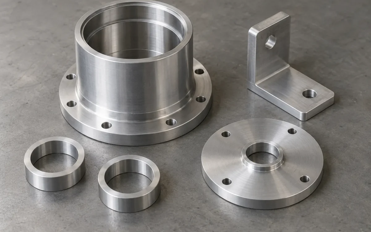
로봇 액추에이터 부품 가공: 하우징·커버·플랜지 제작
ROBOT JOINT · PRECISION COMPONENTS
로봇 액추에이터 부품 가공: 하우징·커버·플랜지 제작
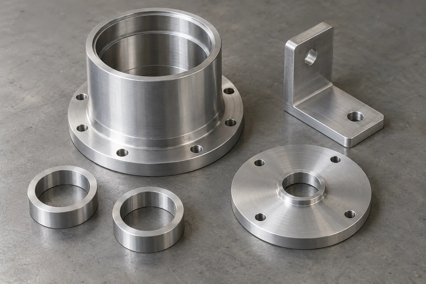
로봇 액추에이터에는 모터·감속기와 함께 하우징, 전후면 커버, 베어링 지지부, 플랜지, 브래킷과 스페이서가 필요합니다. 이 금속 기구 부품들은 회전축의 위치를 유지하고, 관절 하중을 로봇 링크에 전달하며, 배선과 방열을 위한 공간을 구성합니다.
베어링을 지지하는 내경과 감속기가 안착하는 면은 서로 다른 기능을 가지지만 같은 조립 기준으로 연결됩니다. 두 기준이 어긋나면 부품 하나의 지름이 도면에 맞더라도 조립 간섭이나 회전 저항이 발생할 수 있습니다. 커버와 플랜지의 체결 상태 역시 내부 부품의 위치와 지지 조건에 영향을 줍니다.
로봇 액추에이터 부품 가공에서는 개별 치수와 함께 부품 사이의 기준축·접촉면·조립 간격을 관리해야 합니다. 선삭과 밀링의 공정 순서, 박육부 고정 방식, 표면처리 후 치수는 이러한 관계를 실제 형상으로 구현하기 위한 제작 조건입니다.
1. 로봇 액추에이터에 필요한 금속 기구 부품
부품마다 필요한 공정은 다릅니다. 원통형 내경과 외경은 선삭을 중심으로 검토하고, 배선 포켓·측면 개구부·비대칭 체결홀은 밀링 공정과 연결합니다. 회전 대칭 형상과 비대칭 형상이 함께 있으면 선삭과 밀링을 조합하고, 기준면의 연결과 공구 접근성을 고려해 공정 순서를 정합니다.
| 구성 부품 | 액추에이터 내부의 역할 | 주요 가공 형상과 검토 항목 |
|---|---|---|
| 모터·감속기 하우징 | 구동 요소의 위치를 유지하고 장착부로 하중과 열을 전달합니다. | 원통 내경, 베어링 단차, 장착면, 경량화 포켓과 배선 통로를 가공합니다. 벽 두께와 기준축의 관계를 검토합니다. |
| 전면·후면 커버 | 내부 부품을 보호하고 케이블·커넥터 및 조립 공간을 구성합니다. | 맞춤 단차, 볼트홀, 씰 홈과 개구부를 검토합니다. 얇은 원판의 평면도와 체결 후 변형이 주요 항목입니다. |
| 베어링 지지부·캡 | 베어링의 반경·축 방향 위치를 정하고 지지합니다. | 지지 내경, 어깨면, 누름면과 나사부를 가공합니다. 지정 베어링의 끼워맞춤·받침 형상을 적용합니다. |
| 장착 플랜지·브래킷 | 관절 모듈과 로봇 링크 또는 프레임을 연결합니다. | 중심을 맞추는 파일럿 단차, 장착면, 홀 패턴과 포켓을 검토합니다. 하중 전달 부위의 단면을 보존합니다. |
| 스페이서·부시 | 조립 간격, 축 방향 위치와 지지 조건을 맞춥니다. | 내·외경, 길이, 양쪽 단면과 홈을 선삭합니다. 길이 편차와 단면의 기울기를 함께 관리합니다. |
| 단순 축·허브류 | 지정된 회전부와 결합부 사이의 위치·토크 전달 구조를 구성합니다. | 단차 외경, 내경, 홈과 체결부를 검토합니다. 열처리·연삭·밸런싱 등의 추가 요구를 공정에 반영합니다. |
부품의 가공 조건은 크기와 소재 상태, 기능 공차, 후처리 및 검사 방법에 따라 달라집니다. 모터·감속기·베어링의 장착 사양은 하우징과 결합 부품의 치수 기준이 됩니다. 가공품의 치수 확인과 조립된 관절의 구동 평가는 각각의 요구사항에 따라 연결합니다.
기존 구동부에 맞춘 금속 바디 제작
구매한 모터와 감속기를 사용하는 경우에도 관절 바디가 표준품으로 완성되는 것은 아닙니다. 링크 방향, 배선 위치, 외경 제한, 조립 순서에 따라 하우징과 커버가 달라집니다. 같은 구동부를 유지하면서 장착 플랜지나 커넥터 개구부를 변경하는 프로젝트도 금속 부품 제작의 대상이 됩니다.
이때 부품 외형만 전달하기보다 구동부 공급사의 장착 도면과 조립 단면을 함께 확인해야 합니다. 모터 고정자와 하우징의 결합 방식, 감속기 파일럿 치수, 베어링 지지면과 볼트 접근 공간이 실제 가공 형상에 반영되기 때문입니다.
2. 하우징 가공의 중심은 내경·단차·장착면의 관계입니다
액추에이터 하우징에는 여러 기능면이 한 부품 안에 모입니다. 모터를 수용하는 내경, 베어링이 들어가는 좌면, 감속기와 결합하는 기준면, 커버가 맞물리는 단차가 대표적입니다. 각각의 치수뿐 아니라 서로 어떤 축과 면을 기준으로 가공하는지가 중요합니다.
베어링 좌면과 감속기 장착면의 기준 연결
하우징의 베어링 좌면 내경이 도면 규격 안에 들어오더라도 그 축선에 대해 감속기 장착면이 기울어져 있으면 조립 상태가 달라집니다. 따라서 지름 공차와 함께 필요한 원통도, 기준축에 대한 런아웃, 장착면의 직각도·평면도 및 홀 위치를 기능별로 구분합니다.
회전 대칭 형상은 가능한 공정에서 관련 내경과 단면을 함께 가공하는 방법을 검토합니다. 뒤집어 가공하거나 다른 설비로 옮길 때는 앞 공정에서 만든 기준을 다시 잡는 방식과 접촉 위치를 정합니다. 재고정 횟수를 줄이는 것뿐 아니라, 남는 재고정의 기준을 일관되게 유지하는 것이 중요합니다.
베어링 끼워맞춤과 받침 형상
베어링을 단단히 고정하기 위해 하우징 좌면의 내경을 무조건 작게 가공하는 방식은 적절하지 않습니다. 베어링 형식, 각 링에 대한 하중 방향이 고정되는지 회전하는지, 하중 크기, 하우징 재질 및 운전 온도에 따라 적정 끼워맞춤이 달라집니다. 가공 도면에는 선택한 베어링의 권장 장착 조건이 반영되어야 합니다.
베어링이 닿는 어깨면의 높이와 모서리도 함께 확인합니다. 축·하우징의 모서리가 베어링 모따기와 간섭하면 어깨면에 완전히 밀착되지 않을 수 있습니다. 얇은 베어링을 누르는 캡과 플랜지는 체결 시 지지면을 고르게 유지할 수 있도록 두께와 볼트 배치를 검토합니다.
내경 검사와 조립 기준의 일치
치수 확인에는 도면이 요구하는 형상과 기준을 재현할 수 있는 측정 방법이 필요합니다. 내경의 한 위치만 확인해서는 축 방향 변화나 원주 방향 변형을 모두 판단할 수 없습니다. 측정 위치, 부품 온도, 지지 상태와 표면처리 전후 구분을 검사 조건에 포함합니다.
도면에는 중요 치수와 측정 기준, 필요한 형상·위치 확인 항목을 명시합니다. 검사 기록에는 측정값과 함께 부품의 지지 상태 및 확인 조건을 남깁니다. 부품 치수 합격과 조립 후 회전 저항·진동·온도 검증은 서로 연결되는 별도의 평가 항목입니다.
3. 경량 하우징의 벽 두께와 가공 순서
로봇 관절의 금속 부품은 중량과 강성을 동시에 고려해야 합니다. 외벽을 얇게 만들고 포켓을 확대하면 질량을 줄일 수 있지만, 절삭 중 공구 힘과 고정 압력에 대한 변형도 커질 수 있습니다. 특히 베어링 좌면 주변과 볼트 체결부까지 동일하게 얇게 만드는 형상은 검토가 필요합니다.
고정 상태와 자유 상태에서 달라지는 내경
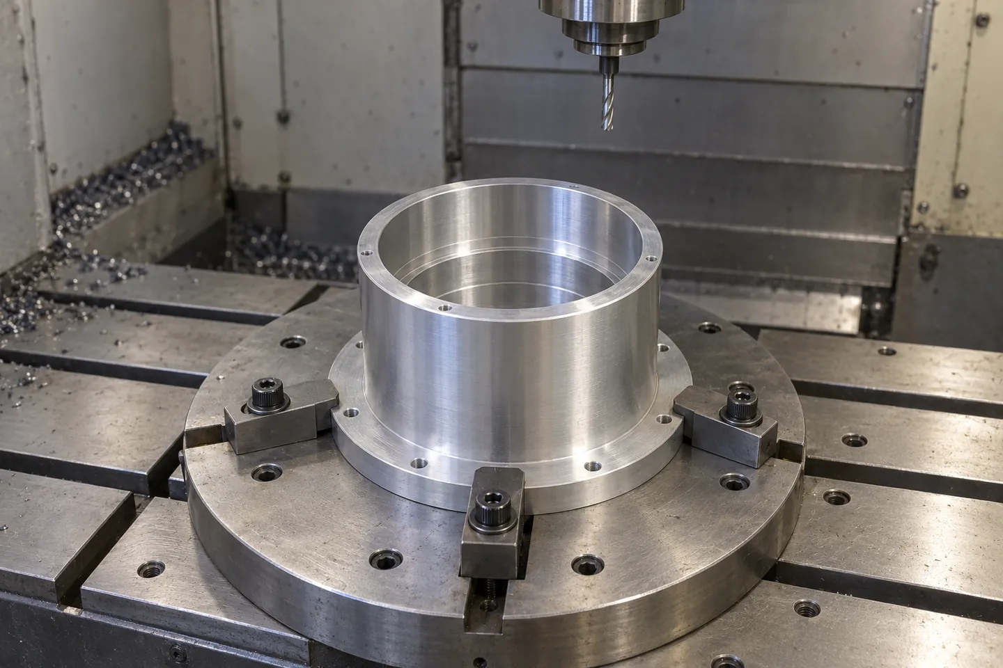
얇은 원통을 강하게 잡은 상태에서 내경을 정삭하면 고정을 해제한 뒤 형상이 변할 수 있습니다. 도면 치수를 맞추려면 고정 압력을 조정하고, 접촉 면적과 지지 위치를 확보하며, 중요 면을 어떤 순서로 마무리할지 정해야 합니다.
고정 방식은 외경을 직접 잡는 방식, 전용 연질 죠, 보조 지지 또는 가공용 여유부를 사용하는 방법 중에서 형상에 맞춰 선택합니다. 외관면의 눌림과 기능면 변형을 함께 고려하며, 특정 고정 방식 하나를 모든 부품에 적용하지 않습니다.
황삭·정삭 분리와 잔여 강성 확보
소재 제거가 진행되면 부품의 강성과 응력 상태가 바뀝니다. 따라서 큰 포켓을 가공하는 순서, 내·외경에 남겨 두는 가공 여유, 얇은 벽의 정삭 시점을 함께 검토합니다. 중요한 내경을 먼저 완성한 뒤 주변을 크게 제거하면 최종 형상이 영향을 받을 수 있습니다.
공정 사이의 치수 확인은 변형이 발생한 단계를 찾는 데 도움이 됩니다. 다만 모든 소재에 응력 제거 열처리를 일괄 적용하지는 않습니다. 합금과 열처리 상태, 형상, 제거량 및 허용 변형을 확인한 뒤 필요한 공정만 지정합니다.
내부 모서리와 공구 접근성
깊은 포켓, 작은 내부 모서리 반경, 긴 돌출 길이가 동시에 요구되면 작은 공구의 강성과 가공 효율에 부담이 생깁니다. 조립 간섭이 없는 범위에서 내부 반경을 조정하거나 포켓 깊이를 나누면 공구 선택과 정삭 조건의 여유가 커집니다.
5축이나 복합가공도 형상 접근성과 공정 연결을 위한 선택입니다. 모든 부품에서 가공 시간이나 가격이 자동으로 줄어드는 것은 아닙니다. 부품을 돌려 잡는 횟수, 치구 제작, 중요 면의 정밀도와 실제 수량을 함께 비교해야 합니다.
4. 커버·플랜지·브래킷의 제작 조건
하우징 주변 부품은 조립 위치와 체결 상태를 결정합니다. 커버의 단차는 조립 위치를 정하고, 플랜지는 하중을 전달하며, 브래킷은 로봇 링크와 관절의 상대 위치를 유지합니다. 외관 형상과 구멍 수가 비슷해도 기능에 따라 가공 기준이 달라집니다.
커버: 평면도·배선 공간·씰 홈
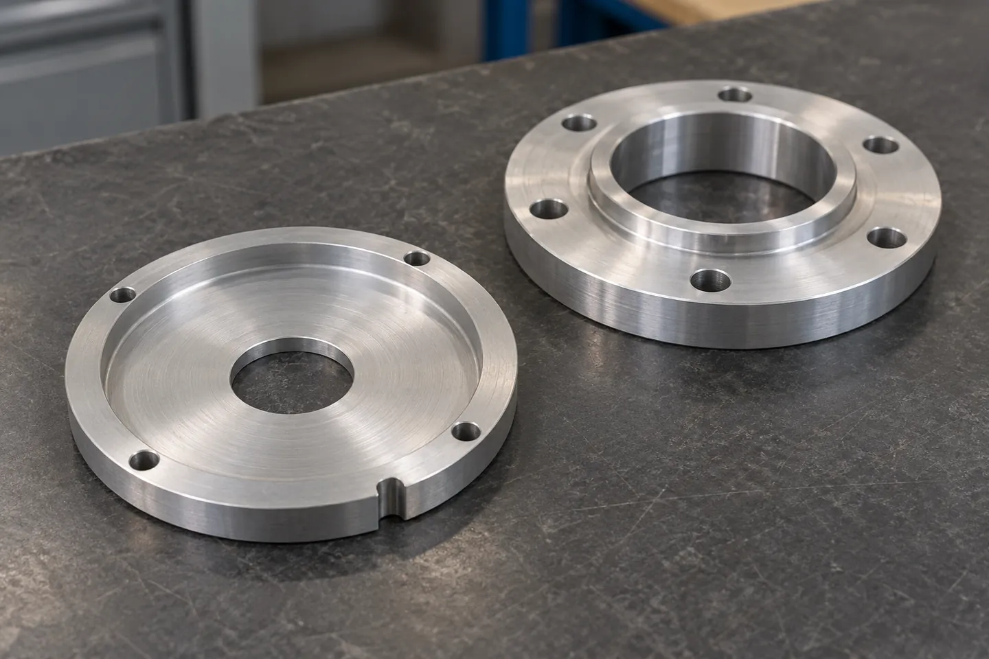
얇은 커버에서는 볼트를 조이는 위치에 따라 접촉면이 변형될 수 있습니다. 맞물리는 단차와 체결면, 볼트 주변 두께를 함께 검토합니다. 커넥터 개구부는 외형 치수뿐 아니라 체결 공구가 들어갈 공간, 케이블 굽힘과 내부 부품의 간섭까지 도면에 반영해야 합니다.
씰 홈이 있는 경우에는 홈 폭·깊이·모서리와 접촉면 상태를 지정합니다. 홈을 가공했다는 사실만으로 방수 성능이 정해지지는 않습니다. 씰 재료와 압축 조건, 체결 구조 및 완성 조립품 시험을 기준으로 요구 형상을 확정합니다.
장착 플랜지: 파일럿 단차와 볼트 패턴
파일럿 단차는 두 부품의 중심을 맞추고, 체결면은 축 방향 위치를 정하는 데 사용됩니다. 볼트홀에 여유가 있는 구조에서는 홀 위치만으로 중심 정렬을 보장할 수 없습니다. 어느 면과 지름이 조립 위치를 결정하는지 먼저 명확히 해야 합니다.
플랜지가 토크와 굽힘 모멘트를 전달하는 경우에는 볼트 체결 조건과 단면 형상도 중요합니다. 가공 측에서는 장착면·단차·홀 패턴의 관계와 버를 관리하고, 설계 측에서는 체결부의 하중·미끄럼·피로 조건을 검증합니다. 체결면 주변의 과도한 경량화 포켓은 이 관계를 확인한 뒤 적용합니다.
브래킷: 양쪽 장착면과 측면 홀의 관계
브래킷은 외형을 다듬는 작업보다 장착면 간 거리와 각도, 홀 축의 위치를 연결하는 작업이 중요합니다. 양쪽 귀 형상이 있는 부품은 어느 면을 기준으로 홀을 가공하고 검사할지 정합니다. 홀 사이 공간이 좁으면 공구와 검사 접근성도 달라집니다.
일체형 가공은 조립 이음부를 줄일 수 있고, 분할형 구조는 소재 제거량이나 공구 접근 부담을 줄일 수 있습니다. 어느 방식이 적합한지는 강성, 조립 공차, 중량과 수량에 따라 판단합니다. 선택한 구조에 따라 공정 순서와 지그의 지지 위치도 달라집니다.
5. 스페이서·부시·축류와 소형 결합 부품
스페이서와 부시의 길이·단면 관리
스페이서는 작고 단순해 보여도 조립 간격과 축 방향 위치에 영향을 줍니다. 길이 편차가 누적되거나 양쪽 단면이 기울어지면 체결 상태와 접촉 분포가 달라질 수 있습니다. 베어링 사이에 배치되는 부품은 내륜·외륜 중 어느 면에 힘을 전달하는지까지 구분해야 합니다.
내·외경, 길이, 단차와 홈은 선삭을 중심으로 가공하며, 서로 연결되는 지름과 단면의 기준을 유지해야 합니다. 부시의 재질과 끼워맞춤은 상대 부품, 마모·부식 환경 및 조립·교체 방법에 맞춰 정합니다. 단순한 원통 형상이라도 기능면의 표면 상태와 모서리 처리를 함께 지정하는 것이 좋습니다.
축·허브의 추가 공정 구분
단차 축과 허브는 선삭을 중심으로 검토할 수 있습니다. 다만 고속 회전축의 밸런싱, 열처리 후 연삭, 정밀 스플라인이나 특수 치형은 별도의 제작 조건입니다. 도면에는 추가 공정의 순서와 최종 치수·검사 요구를 구분해 표시해야 합니다.
감속기를 지지하는 하우징·플랜지 가공과 감속기 내부의 핵심 치형 제작은 구분합니다. 로봇 관절용 부품이라는 공통점만으로 동일한 공법·공차·검사 체계를 적용할 수는 없습니다.
소형 복잡 형상의 MIM 적용 검토
작은 결합 부품이나 고정부품에 곡면·홈·돌출부가 모여 있고 반복 생산 수량이 확보되면 MIM도 공법 후보가 될 수 있습니다. 부품 역할, 적용 소재, 형상과 예상 수량에 따라 성형·소결 조건과 후가공할 기능면이 달라집니다.
이 선택은 알루미늄 하우징 가공과 별도로 다룹니다. 소결 수축과 변형, 필요한 면의 후가공, 강도·피로 요구 및 금형 비용을 함께 비교해야 합니다. 시제품 CNC 형상을 그대로 MIM으로 옮기는 것보다 공법에 맞는 형상 검토가 선행되어야 합니다.
6. 소재·방열 접촉면·표면처리를 함께 정하는 이유
알루미늄 바디의 소재 지정
알루미늄은 관절 바디의 중량과 가공성을 검토할 때 주요 후보가 됩니다. 그러나 ‘알루미늄’이라는 재질명만으로 발주 조건이 완성되지는 않습니다. 합금 등급, 열처리 상태, 공급 형태와 표면처리 요구를 도면 또는 구매 사양에 명시해야 합니다.
소재 강도가 높아져도 같은 형상에서 탄성 변형이 같은 비율로 줄어드는 것은 아닙니다. 체결부의 소성 변형 여유, 탄성 강성, 열전달, 내식성과 가공 후 안정성을 구분해 검토합니다. 베어링 누름부나 하중이 집중되는 부품은 알루미늄 바디와 다른 재질을 사용할 수도 있습니다.
모터 장착면과 열전달 경로
모터에서 발생한 열이 하우징을 통해 빠져나가려면 장착면의 접촉 조건이 유지되어야 합니다. 고정자와 수용부 사이의 결합 방식, 접촉 면적, 접착층이나 열전달 재료, 실제 냉각 구조에 따라 결과가 달라집니다. 가공 단계에서는 공급사 설치 조건에 맞는 수용부 치수와 표면 상태를 구현합니다.
알루미늄 하우징과 베어링강으로 만든 링은 온도 변화에 따른 팽창량도 다릅니다. 상온에서의 조립 치수가 운전 중 동일하게 유지된다고 가정할 수 없습니다. 설계에서 정한 온도 조건과 끼워맞춤 요구를 가공·검사 기준으로 전달해야 합니다.
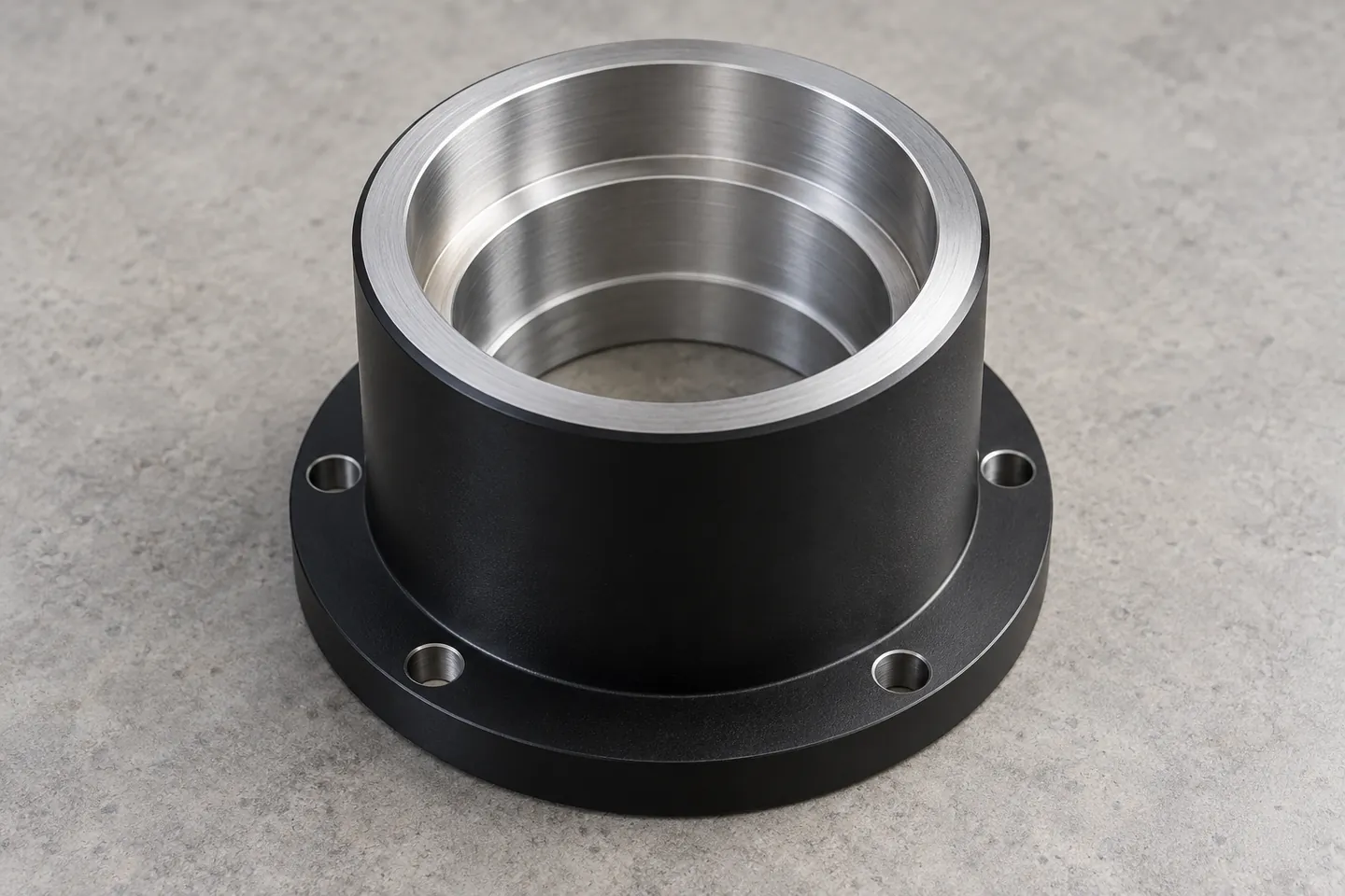
아노다이징과 최종 치수
표면처리는 외관 공정이면서 조립 치수에 영향을 주는 공정입니다. 아노다이징의 피막 성장과 전처리에서 발생하는 소재 제거는 내경·외경·단차에 영향을 줄 수 있습니다. 따라서 피막 두께와 최종 치수, 마스킹 범위를 가공 전에 정합니다.
| 구분할 표면 | 도면에 반영할 조건 | 제작 단계의 확인 사항 |
|---|---|---|
| 베어링·파일럿 끼워맞춤면 | 후처리 후 치수인지, 마스킹하는 면인지 지정합니다. | 처리 전 가공 여유와 최종 확인 시점을 연결합니다. |
| 열전달·전기 접촉면 | 접촉 목적, 표면 상태와 피막 허용 여부를 구분합니다. | 기능면에 외관용 마감 조건을 일괄 적용하지 않습니다. |
| 외관면 | 색상·광택·결 방향과 허용 외관 기준을 정합니다. | 합의한 샘플과 함께 취급·포장 중 손상 방지를 검토합니다. |
| 나사·씰 관련 형상 | 처리 후 체결·밀봉에 필요한 치수와 표면 조건을 지정합니다. | 피막과 전처리 영향을 고려해 검사 방법을 정합니다. |
기능면과 외관면은 요구하는 표면 상태가 다르므로 가공 조건과 표면처리 범위를 구분해야 합니다. 피막의 성장 비율을 모든 합금·공정에 동일한 값으로 적용하거나, 색상만으로 처리 상태를 판단하지 않습니다.
7. 시제품에서 반복 생산으로 이어지는 제작 계획
시제품은 조립 간섭과 공정 접근성을 확인하는 단계이고, 반복 생산은 같은 도면과 기준으로 품질을 유지하는 단계입니다. 첫 제품이 한 번 조립된다는 사실만으로 공급 안정성이 확보되지는 않습니다. 도면 개정, 중요 치수, 후처리와 검사 조건을 생산 기준으로 정리해야 합니다.
결합 부품과 기준면을 확인하고 선삭·밀링 순서, 고정 방식과 후처리 범위를 정합니다.
중요 치수와 실제 조립 결과를 대조하고 간섭·버·체결 변형의 원인을 구분합니다.
확정 도면, 치구 조건, 공구 관리와 검사 항목을 연결해 변경 이력을 유지합니다.
조립 피드백을 가공 조건으로 되돌리는 방식
예를 들어 커버 체결 전에는 회전이 원활하지만 체결 후 저항이 증가한다면 내경 치수 하나만 수정해서 해결하려 해서는 안 됩니다. 부품의 축 방향 간격, 누름면, 체결 순서와 토크, 지지부 변형 등 조립 조건을 함께 확인해야 합니다.
반대로 특정 하우징에서만 간섭이 발생한다면 내경의 위치별 측정, 모서리와 버, 표면처리 두께, 관련 부품의 치수 조합을 확인합니다. 이러한 검토를 통해 설계 변경이 필요한 문제와 가공·조립 조건으로 관리할 문제를 구분할 수 있습니다.
원가에 영향을 주는 형상과 요구 조건
제작 원가는 소재 중량만으로 결정되지 않습니다. 제거해야 하는 소재량, 깊은 내경과 작은 공구, 재고정 횟수, 전용 치구, 후처리 마스킹, 측정 범위와 수량이 함께 작용합니다. 모든 면에 동일하게 엄격한 공차를 부여하면 기능상 이득 없이 가공·검사 부담이 늘어날 수 있습니다.
원가와 제작성을 검토할 때는 반드시 유지해야 하는 기능 치수와 조정 가능한 외형·포켓·모서리 조건을 구분합니다. 시제품 수량과 예상 반복 생산량에 따라 초기 치구 비용과 반복 가공 시간의 비중도 달라집니다.
8. 로봇 액추에이터 부품의 도면·제작 사양
하우징·커버·플랜지·스페이서가 조립되는 구조에서는 부품별 도면과 조립 단면이 같은 기준을 사용해야 합니다. 부품 도면에는 치수와 공차를, 조립 도면에는 상대 위치와 체결 관계를 표시합니다. 구동 사양 가운데 가공 형상에 영향을 주는 하중·온도·장착 조건도 함께 정리합니다.
| 자료 | 포함할 내용 | 가공·검사와의 연결 |
|---|---|---|
| 2D 도면·3D 데이터 | 도면 개정, 단위, 기준면, 중요 치수·공차와 표면 상태를 포함합니다. | 형상·공구 접근·공정 순서·검사 범위를 검토합니다. |
| 결합 부품·조립 단면 | 베어링·모터·감속기 장착 도면과 커버·플랜지의 결합 관계를 전달합니다. | 지지면·단차·끼워맞춤·체결 접근성을 확인합니다. |
| 소재·후처리 사양 | 합금과 상태, 피막 종류, 외관 기준, 마스킹 면을 지정합니다. | 소재 조달과 처리 후 최종 치수 조건을 정합니다. |
| 사용 조건·검사 요구 | 형상에 영향을 주는 하중·온도, 중요 관리 특성, 성적서 요구를 전달합니다. | 설계 기준과 가공·측정 조건을 연결합니다. |
| 수량·제작 단계 | 시제품 수량, 예상 반복 생산량과 도면 확정 시점을 정합니다. | 전용 치구와 공정 구성, 후처리 및 검사 계획에 반영합니다. |
조립 기준을 완성 부품의 치수로 연결하는 공정
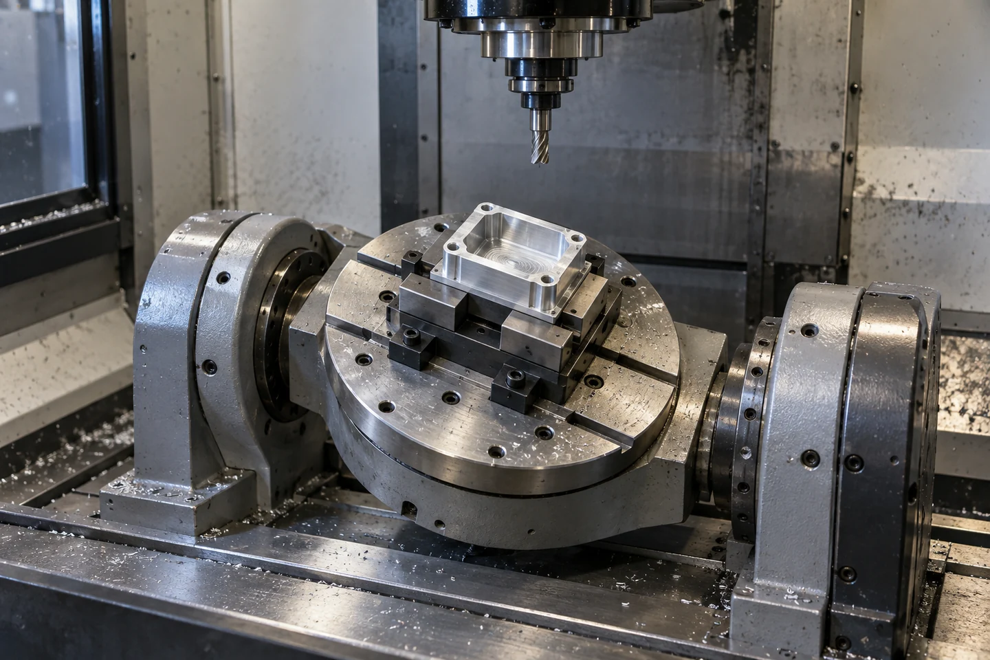
하우징의 원통부와 맞춤 단차에는 정밀선반가공을, 포켓·측면 홀·장착면에는 CNC·MCT 정밀가공을 적용합니다. 표면처리가 필요한 부품은 피막과 마스킹 조건까지 포함해 최종 치수를 정합니다. 각 공정이 같은 조립 기준을 유지해야 개별 부품의 치수가 실제 관절 구조에서도 의미를 갖습니다.
English edition
Machining Robot Actuator Components: Housings, Covers and Flanges
Robot actuators require housings, front and rear covers, bearing supports, flanges, brackets and spacers alongside motors and reducers. These metal mechanical components maintain shaft location, transmit joint loads to robot links, and provide space for wiring and heat transfer.
A bearing-seat bore and a reducer mounting face perform different functions but share assembly references. If those references are misaligned, interference or increased rotational resistance can occur even when an individual diameter meets its drawing requirement. The fastening condition of covers and flanges also affects the location and support of internal components.
Machining robot actuator components requires control of shared datum axes, contact surfaces and assembly spacing as well as individual dimensions. Turning and milling sequences, thin-wall workholding and dimensions after surface treatment determine how these relationships are realized in the finished parts.
1. Metal mechanical components required in robot actuators
Different components require different processes. Cylindrical bores and outside diameters are generally reviewed around turning operations. Wiring pockets, side openings and asymmetric hole patterns are connected to milling operations. Where rotationally symmetric and asymmetric features coexist, turning and milling are combined. Operation order depends on datum continuity and tool access.
Component families and machining features
| Component | Function within the actuator | Main features and review items |
|---|---|---|
| Motor and reducer housings | Locate drive elements and transmit loads and heat to mounting structures. | Machine cylindrical bores, bearing shoulders, mounting faces, weight-reduction pockets and wiring passages. Review wall thickness relative to the datum axis. |
| Front and rear covers | Protect internal components and provide space for cables, connectors and assembly. | Review locating steps, bolt holes, seal grooves and openings. Thin-disc flatness and deformation after fastening are key considerations. |
| Bearing supports and caps | Locate and support bearings radially and axially. | Machine support bores, shoulders, retaining faces and threads. Apply the fits and abutment geometry required for the specified bearing. |
| Mounting flanges and brackets | Connect the joint module to a robot link or frame. | Review locating pilots, mounting faces, hole patterns and pockets. Preserve material in load-transmitting sections. |
| Spacers and bushings | Establish assembly spacing, axial location and support conditions. | Turn inside and outside diameters, lengths, end faces and grooves. Control length variation together with end-face orientation. |
| Simple shafts and hubs | Provide specified locating and torque-transmitting interfaces between rotating and mating parts. | Review stepped diameters, bores, grooves and fastening features. Additional heat treatment, grinding or balancing requirements are incorporated into the process plan. |
Connecting component requirements to manufacturing
Machining conditions depend on part size, material condition, functional tolerances, finishing and inspection methods. Motor, reducer and bearing mounting specifications establish dimensional requirements for the housing and mating components. Dimensional verification of individual parts and testing of the assembled joint are connected through their respective requirements.
Metal bodies adapted to existing drive components
Using purchased motors and reducers does not make the complete joint body a standard item. Link orientation, wiring position, diameter restrictions and assembly sequence change the housing and cover requirements. A project that retains the same drive components but changes a mounting flange or connector opening can also require custom metal parts.
Reviewing only the outer shape is insufficient. Drive-component mounting drawings and assembly sections should also be provided. The stator retention method, reducer pilot dimensions, bearing support faces and space for bolt access all affect the geometry that must be machined.
2. Relationships between bores, shoulders and mounting faces
An actuator housing combines several functional surfaces in one part. These include the motor bore, bearing seats, reducer mounting references and locating steps for the covers. Individual dimensions matter, but so do the axes and faces used as their common manufacturing references.
Connecting bearing-seat and reducer-mounting datums
A housing’s bearing-seat bore can meet its diameter tolerance while the reducer mounting face is tilted relative to its axis. The assembled condition will then differ from the intended arrangement. Diameter tolerance, required cylindricity, runout relative to the datum axis, mounting-face perpendicularity and flatness, and hole positions should therefore be specified according to function.
For rotationally symmetric features, the process review considers machining related bores and end faces together wherever practical. When a part must be reversed or transferred to another machine, the method of recovering the previous datum and the fixture contact locations must be defined. Reducing the number of setups is useful, but maintaining consistent references through the remaining setups is equally important.
Bearing fits and abutment geometry
Making the housing’s bearing-seat bore smaller simply to hold the bearing more tightly is not an appropriate general rule. The correct fit depends on bearing type, whether the load direction is stationary or rotating relative to each ring, load magnitude, housing material and operating temperature. The machining drawing should reflect the selected bearing’s recommended mounting conditions.
The height and corner geometry of the bearing shoulder also require review. Interference between a shaft or housing corner and the bearing chamfer can prevent full seating against the shoulder. Caps and flanges retaining thin bearings require suitable thickness and bolt placement to keep the supporting surface even during fastening.
Matching bore inspection to assembly datums
Dimensional verification requires methods capable of reproducing the geometry and references specified on the drawing. Checking a bore at only one location cannot establish all axial variation or circumferential deformation. Measurement locations, part temperature, support condition and whether inspection occurs before or after surface treatment should be included in the inspection requirements.
Drawings specify critical dimensions, measurement references and required form or position checks. Inspection records should retain the part support condition and measurement conditions alongside the measured values. Component dimensional acceptance and assembled rotational resistance, vibration and temperature testing are related but separate evaluations.
3. Wall thickness and machining sequence for lightweight housings
Metal components for robot joints must balance mass and stiffness. Thinner outer walls and larger pockets can reduce mass, but can also increase deformation under cutting and clamping forces. Particular care is needed when the same weight-reduction approach extends into bearing-seat regions and bolted connections.
Bore geometry under clamping and after release
A thin cylinder finish-machined while tightly clamped can change shape after release. Meeting the drawing requires appropriate clamping pressure, sufficient contact area and support, and a defined sequence for finishing critical surfaces.
Workholding is selected to suit the geometry, using direct outside-diameter clamping, dedicated soft jaws, auxiliary supports or sacrificial workholding features as appropriate. The assessment considers both marks on cosmetic surfaces and deformation of functional features. One fixture method is not applied indiscriminately to every component.
Separating roughing and finishing while retaining stiffness
Material removal changes both part stiffness and the stress state. The order of large-pocket machining, allowances retained on inside and outside diameters, and the timing of thin-wall finishing should therefore be planned together. Finishing a critical bore before removing a substantial amount of surrounding material can affect its final geometry.
Dimensional checks between operations help identify the stage at which deformation develops. Stress-relief heat treatment is not automatically appropriate for every material. Only the necessary operations should be specified after considering alloy, temper, geometry, removal volume and allowable deformation.
Internal corners and tool access
Deep pockets, small internal corner radii and long tool overhangs place combined demands on tool stiffness and machining efficiency. Where assembly clearance permits, adjusting internal radii or dividing pocket depths can broaden the available tooling and finishing options.
Five-axis and combined machining are also choices for improving feature access and connecting operations. They do not automatically reduce machining time or price for every part. The comparison must include refixturing, fixture manufacture, critical-surface accuracy and actual quantities.
4. Manufacturing requirements for covers, flanges and brackets
Components surrounding the main housing determine assembly location and fastening conditions. Cover steps establish location, flanges transmit loads, and brackets maintain the relationship between the joint and robot links. Parts with similar outlines and hole counts can require different manufacturing datums because their functions differ.
Covers: flatness, wiring space and seal grooves
A thin cover can deform locally as bolts are tightened. Its locating step, fastening face and thickness around the bolts should be reviewed together. Connector openings require more than the connector’s outer dimensions. Drawings must also account for tool access, cable bending and interference with internal components.
For a seal groove, specify width, depth, corner geometry and the condition of contacting surfaces. A machined groove alone does not establish water resistance. The required geometry is determined from the seal material, compression conditions, fastening arrangement and testing of the completed assembly.
Mounting flanges: locating pilots and bolt patterns
A locating pilot can center two components, while the mating face establishes axial position. Where bolt holes provide clearance, hole location alone cannot guarantee concentric assembly. The surfaces and diameters that determine assembly location must first be made explicit.
When a flange transmits torque and bending moments, bolt conditions and section geometry also matter. Manufacturing controls the relationships between the mounting face, locating step and hole pattern, together with burrs. Design verification addresses loading, slip and fatigue at the connection. Aggressive weight-reduction pockets near the fastening face should be introduced only after these relationships have been reviewed.
Brackets: opposing mounting faces and lateral holes
Bracket manufacture requires control of mounting-face distances and angles and the positions of hole axes. These relationships matter more than the external contour alone. For a part with two opposing lugs, the drawing should define the references used to machine and inspect the holes. Narrow space between the lugs can also restrict cutting-tool and inspection access.
Machining a bracket as one piece can reduce assembly joints. A split construction can reduce material removal or improve access. The suitable approach depends on stiffness, assembly tolerances, mass and quantity. The selected structure also changes the operation sequence and fixture support locations.
5. Spacers, bushings, shafts and small mating components
Spacer and bushing length and end-face control
Spacers can appear simple, yet they affect assembly spacing and axial location. Accumulated length variation or tilted end faces can change fastening conditions and contact distribution. For a spacer positioned between bearings, the design must distinguish whether force is transmitted through an inner-ring or outer-ring face.
Diameters, lengths, shoulders and grooves are produced primarily by turning, while maintaining the references connecting the diameters and end faces. Bushing material and fit are selected around the mating component, wear and corrosion conditions, and the methods of assembly and replacement. Even a simple cylindrical part benefits from explicit requirements for functional surface condition and edge finishing.
Additional operations for shafts and hubs
Stepped shafts and hubs can be reviewed primarily around turning. High-speed shaft balancing, grinding after heat treatment, precision splines and special tooth profiles are separate manufacturing requirements. Drawings should distinguish the sequence of additional operations, final dimensions and inspection requirements.
Machining a housing or flange that supports a reducer is distinct from manufacturing the reducer’s critical internal tooth geometry. Their shared use in a robot joint does not make the same process, tolerance scheme or inspection system appropriate to both.
Considering MIM for small, complex components
Metal injection molding, or MIM, may be a candidate for small mating or retaining parts that combine curved surfaces, grooves and projections, provided sufficient repeated production volume is available. Component function, material, geometry and expected quantity determine molding and sintering conditions and which functional surfaces require secondary machining.
This option is evaluated separately from aluminum housing machining. The comparison must include sintering shrinkage and distortion, secondary machining of critical surfaces, strength and fatigue requirements, and tooling cost. Geometry should be reviewed for the intended process before transferring a CNC prototype directly to MIM.
6. Coordinating material, thermal interfaces and surface treatment
Specifying aluminum for joint bodies
Aluminum is an important candidate when considering joint-body mass and machinability. Specifying only “aluminum” is not sufficient for procurement, however. Alloy grade, temper, supplied material form and surface-treatment requirements should be stated on the drawing or purchasing specification.
Higher material strength does not reduce elastic deformation by the same proportion in an unchanged geometry. Margin against plastic deformation at fasteners, elastic stiffness, heat transfer, corrosion resistance and stability after machining should be evaluated separately. Bearing retainers or components carrying concentrated loads may use a different material from the aluminum body.
Motor mounting surfaces and heat-transfer paths
For motor heat to pass through the housing, suitable contact conditions must be maintained at the mounting interface. The stator retention method, contact area, adhesive or thermal-interface material, and actual cooling arrangement all affect the result. Machining must provide the receiving dimensions and surface condition required by the supplier’s installation instructions.
An aluminum housing and bearing rings made from bearing steel also expand by different amounts as temperature changes. Room-temperature assembly dimensions cannot be assumed to remain unchanged in operation. The design’s temperature conditions and fit requirements must be carried into machining and inspection criteria.
Anodizing and final dimensions
Surface treatment affects both appearance and assembly dimensions. Anodic coating growth and material removal during pretreatment can change bores, outside diameters and steps. Coating thickness, final dimensions and masking areas should therefore be agreed before machining.
| Surface category | Drawing requirements | Manufacturing checks |
|---|---|---|
| Bearing and pilot fits | State whether dimensions apply after finishing or whether the surface is to be masked. | Connect the pre-treatment machining allowance with the timing of final verification. |
| Thermal and electrical contact surfaces | Define contact function, surface condition and whether a coating is permitted. | Do not apply cosmetic finishing requirements indiscriminately to functional interfaces. |
| Cosmetic surfaces | Define color, gloss, texture direction and appearance acceptance criteria. | Review protection against handling and packaging damage alongside the agreed sample. |
| Threads and seal features | Specify the dimensions and surface conditions needed for fastening or sealing after treatment. | Select inspection methods that account for coating and pretreatment effects. |
Functional and cosmetic surfaces require different surface conditions, so their machining and treatment requirements must be distinguished. A single coating-growth ratio should not be applied to every alloy and process, and color alone should not be used to assess treatment condition.
7. Planning manufacture from prototypes to repeated production
Prototyping checks assembly interference and process access. Repeated production must maintain quality against the same drawing and datums. A first part that assembles successfully once does not establish a stable supply process. Drawing revisions, critical dimensions, finishing and inspection conditions must be formalized as production requirements.
Check mating parts and datums, then define the turning and milling sequence, workholding and finishing scope.
Compare critical dimensions with actual assembly results and distinguish interference, burrs and fastening-induced deformation.
Connect approved drawings, fixture conditions, tool management and inspection items while retaining change records.
Feeding assembly findings back into manufacturing
If rotation is smooth before fastening a cover but resistance increases afterward, changing a single bore dimension is not an adequate first response. Axial spacing, retaining faces, tightening sequence and torque, support deformation and other assembly conditions should be checked together.
If interference occurs only in a particular housing, check bore measurements at multiple locations, corners and burrs, coating thickness and the dimensional combination of mating parts. This helps distinguish a problem requiring a design change from one that can be controlled through machining or assembly conditions.
Geometry and requirements that affect cost
Manufacturing cost is not determined by starting-material mass alone. Removal volume, deep bores, small tools, the number of setups, dedicated fixtures, finishing masks, measurement scope and quantity all contribute. Applying equally tight tolerances to every surface can increase machining and inspection effort without improving function.
Cost and manufacturability reviews distinguish essential functional dimensions from outlines, pockets and corner features that may be adjusted. Prototype quantities and expected repeated-production volumes change the relative importance of initial fixture cost and recurring machining time.
8. Drawings and manufacturing specifications for actuator components
In an assembly of housings, covers, flanges and spacers, component drawings and assembly sections must use consistent references. Component drawings specify dimensions and tolerances; assembly drawings show relative positions and fastening relationships. Load, temperature and mounting requirements that affect the machined geometry should be documented alongside them.
Drawings, interfaces and production requirements
| Information | Contents | Use in manufacturing review |
|---|---|---|
| 2D drawings and 3D data | Include revision, units, datums, critical dimensions, tolerances and surface requirements. | Review geometry, tool access, operation sequence and inspection scope. |
| Mating parts and assembly sections | Provide bearing, motor and reducer mounting drawings and the relationships between covers and flanges. | Verify support faces, steps, fits and access for fastening. |
| Material and finishing specifications | Specify alloy and condition, coating type, appearance criteria and masking areas. | Define material procurement and final dimensional conditions after treatment. |
| Operating and inspection requirements | Provide loads and temperatures that affect the geometry, critical characteristics and report requirements. | Connect design criteria with machining and measurement conditions. |
| Quantities and production stage | Define prototype quantities, expected repeated-production volumes and the timing of drawing release. | Reflect these in dedicated fixtures, process configuration, finishing and inspection planning. |
Connecting assembly datums to finished-part dimensions
Precision turning produces cylindrical housing features and locating steps, while CNC and MCT precision machining produces pockets, lateral holes and mounting faces. For parts requiring surface treatment, final dimensions also account for coating and masking conditions. Maintaining the same assembly references through these operations connects individual part dimensions to the actual joint structure.
추가 정보
로봇 액추에이터 부품 가공 요약
로봇 액추에이터의 하우징·커버·베어링 지지부·플랜지·브래킷·스페이서는 내부 부품의 위치를 유지하고 관절 하중을 전달합니다. 각 부품의 기능에 맞춰 소재·가공 기준·고정 방식·후처리·최종 치수 확인 조건을 정해야 합니다.
주요 제작 조건
- 하우징의 베어링 장착 내경·단차·감속기 장착면을 같은 기능 기준으로 연결합니다.
- 박육부는 절삭 중 고정 상태와 고정 해제 후의 변형을 함께 검토합니다.
- 커버·플랜지는 맞춤 단차·체결면·볼트 패턴과 조립 공간을 구분합니다.
- 스페이서·부시는 길이뿐 아니라 접촉 단면과 힘의 전달 위치를 확인합니다.
- 표면처리 전에 마스킹 면과 처리 후 최종 치수를 지정합니다.
- 도면 개정·초도 조립 피드백·반복 생산 조건을 연결합니다.
로봇 액추에이터에는 어떤 금속 기구 부품이 필요합니까?
하우징, 전후면 커버, 베어링 지지부, 장착 플랜지, 브래킷, 스페이서와 부시가 대표적입니다. 구동 요소의 위치 유지, 하중 전달, 조립 간격, 배선과 방열 공간 등 각 기능에 따라 형상과 가공 조건이 달라집니다.
구매한 모터·감속기를 사용해도 별도의 하우징이 필요합니까?
관절의 외형 제한, 링크 방향, 배선 위치와 조립 순서에 따라 하우징 형상이 달라집니다. 구동부의 장착 도면을 기준으로 베어링 지지면, 고정 방식, 배선 통로와 체결 공구의 접근 공간을 구성해야 합니다.
하우징과 커버·플랜지를 함께 검토하는 이유는 무엇입니까?
각 부품의 치수가 서로 연결되어 조립 위치와 체결 상태를 결정하기 때문입니다. 부품 묶음으로 검토하면 맞춤 단차, 홀 패턴, 축 방향 간격과 후처리 조건의 불일치를 확인하기 쉽습니다.
얇은 하우징에서 주의할 점은 무엇입니까?
절삭력과 고정 압력에 의한 변형, 소재 제거에 따른 강성 변화가 중요합니다. 지지 위치·접촉 면적·황삭과 정삭 순서·중요 면의 마무리 시점을 형상에 맞춰 검토합니다.
모든 내경에 같은 정밀 공차를 적용해야 합니까?
기능별로 구분해야 합니다. 베어링 좌면, 모터 수용부, 단순 배선 통로는 요구 조건이 다릅니다. 결합 부품의 장착 사양과 하중·온도 조건을 기준으로 필요한 치수 및 기하공차를 지정합니다.
아노다이징 이후에도 끼워맞춤 치수를 유지할 수 있습니까?
도면에 처리 후 치수와 피막 조건, 필요한 마스킹 면을 명확히 지정해야 합니다. 가공 여유와 전처리·피막 성장의 영향을 함께 검토하고 합의한 최종 상태에서 치수를 확인합니다.
축·허브와 감속기 내부 부품은 가공 조건이 어떻게 다릅니까?
단차 축과 허브는 선삭을 중심으로 가공하지만 회전 조건에 따라 열처리·연삭·밸런싱이 추가될 수 있습니다. 감속기 내부의 정밀 치형은 별도의 형상과 검사 요구가 있으므로 하우징이나 일반 선삭 부품과 같은 공정으로 일괄 취급하지 않습니다.
부품 제작 도면에는 어떤 정보가 필요합니까?
도면 개정과 단위, 기능 기준면, 중요 치수·공차, 소재와 후처리, 검사 조건을 명시합니다. 결합 부품의 장착 도면과 조립 단면을 함께 구성하고, 시제품과 반복 생산 단계에 맞춰 공정·치구·검사 계획을 정합니다.
관련 가공 기술
관련 태그

Related posts
시계 스프링바 제조: 튜브·핀·숄더 가공과 스프링 선정, 반복 압축·부식 피로 검사
정밀 부품 도면의 표면 거칠기 지시: Ra·Rz 값과 외관·밀봉·접촉 기능의 관계
명품 무브먼트 마감: 앵글라주·블랙 폴리싱·제네바 스트라이프의 정밀 제조
3축 가공과 5축 가공: 공구 접근·셋업·정밀도와 제조 원가 비교

외장 SSD 케이스: 알루미늄 방열 구조와 정밀가공 설계
