세라믹 베젤링: 스테인리스 결합 구조와 열팽창·충격 설계
CERAMIC · STAINLESS STEEL · BEZEL ASSEMBLY
세라믹 베젤링:
스테인리스 결합 구조와 열팽창·충격 설계
광택이 깊은 세라믹 링과 얇게 가공한 스테인리스 지지체가 하나의 외장을 이룹니다. 정교한 베젤링의 완성도는 두 소재의 외관뿐 아니라, 서로 다른 변형을 받아들이는 간극과 접합부에서 결정됩니다.

검은 세라믹 표면과 은색 금속 테두리가 만나는 경계는 작지만 선명합니다. 이 경계가 한쪽만 넓어지거나 높이가 달라지면 전체 원형이 어긋나 보입니다. 외관을 맞추려고 간극을 과도하게 줄이면 조립 중 세라믹 모서리가 손상될 수 있고, 접합층을 불균일하게 만들면 온도 변화와 충격을 받는 위치가 달라집니다.
세라믹 베젤링의 핵심은 단단한 표면과 금속 지지 구조를 결합하면서, 두 소재가 서로를 손상시키지 않도록 하중과 변형의 경로를 설계하는 데 있습니다. 치수 공차, 접합층 두께, 모서리 형상과 조립 순서는 별개의 관리 항목이 아니라 하나의 구조 조건입니다.
1. 세라믹과 316L 스테인리스의 역할 분담
퍼슬랏 갤럭시워치6용 세라믹 메탈 베젤링과 갤럭시워치7용 G스타일 G-1·G-2는 세라믹과 스테인리스의 조합을 살펴볼 수 있는 외장 사례입니다. 갤럭시워치6 자료에는 세라믹과 스테인리스가 함께 표시되어 있으며, G-1·G-2의 금속 소재 표기는 Stainless Steel 316L입니다. 소재명은 316L을 기준으로 구분합니다.
세라믹은 금속이 아니므로 이 구조는 정확히는 이종 소재 결합에 해당합니다. 세라믹의 조성과 소결·가공 상태에 따라 경도, 파괴인성, 열팽창과 표면 품질이 달라집니다. 검은색 외관만으로 지르코니아인지 알루미나인지 판정하거나 특정 경도값을 부여할 수는 없습니다.
| 구성 요소 | 설계에 활용하는 특성 | 함께 고려할 한계 |
|---|---|---|
| 세라믹 상부 링 | 조성과 마감에 따라 높은 표면 경도와 안정적인 광택을 확보할 수 있습니다. | 경도는 낙하 충격에 대한 보증값이 아닙니다. 모서리 결함과 국부 인장응력이 파손에 영향을 줍니다. |
| 316L 금속 지지체 | 얇은 턱, 장착면과 외주 형상을 가공하고 하중을 분산하는 구조를 만들 수 있습니다. | 얇은 단면은 체결·가공·외력에 의해 변형될 수 있습니다. 내식성도 표면 상태와 노출 환경의 영향을 받습니다. |
| 두 소재 사이 접합부 | 위치를 유지하고 사용 하중을 전달합니다. 설계 방식에 따라 변형 차이를 흡수하는 기능도 갖습니다. | 재료명만으로 접합 강도가 정해지지 않습니다. 계면 상태·두께·경화·형상과 온습도 이력을 함께 봅니다. |
G-1·G-2에서 구분할 외관 요소
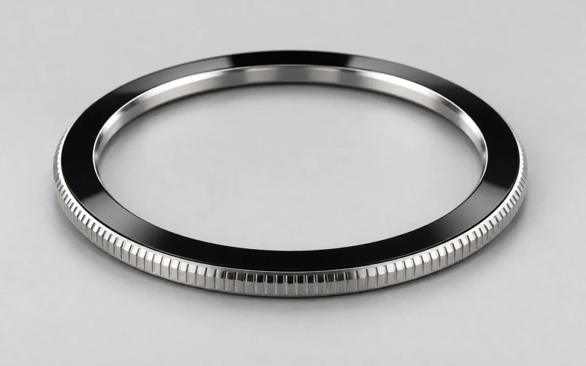
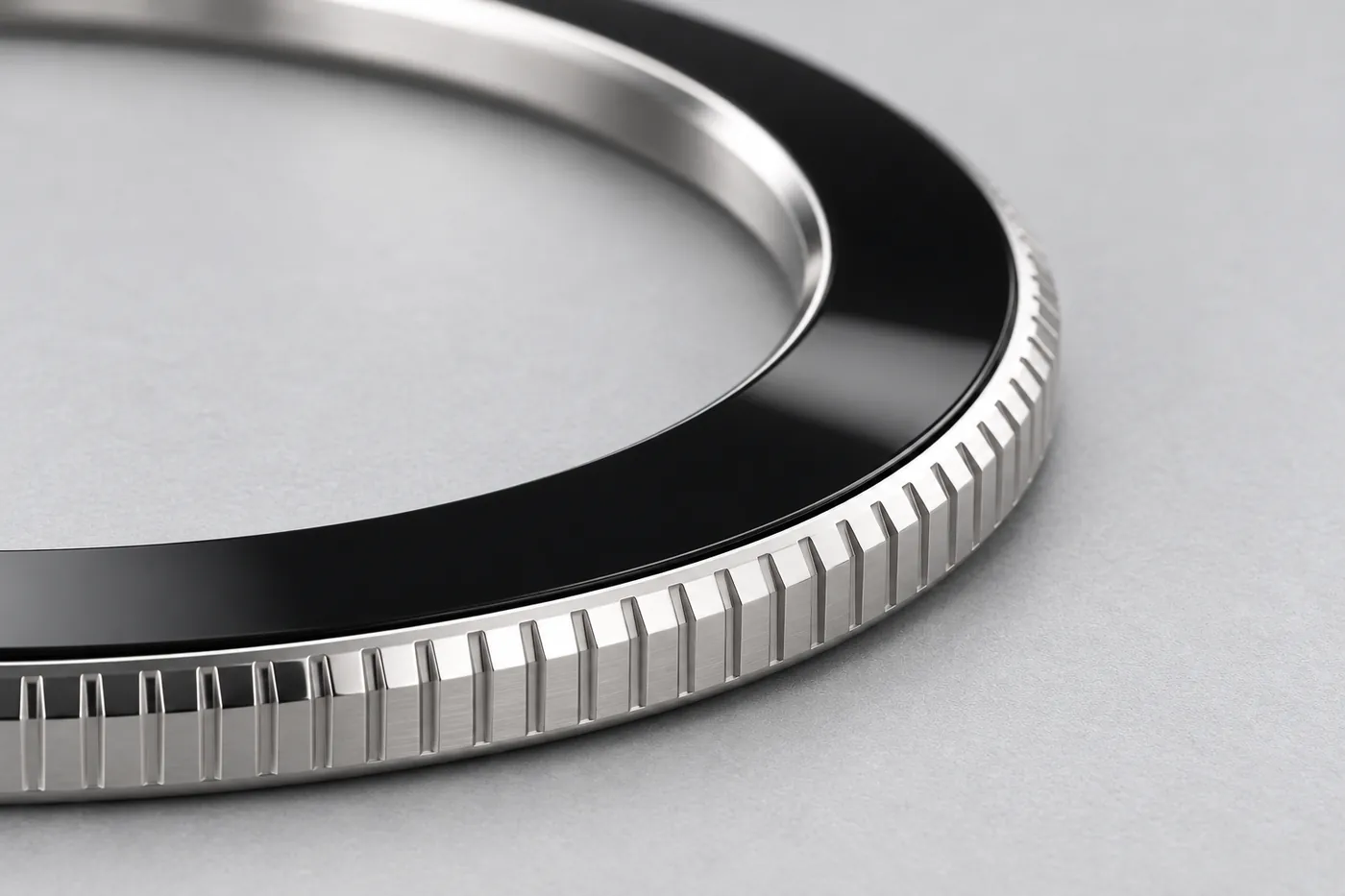
두 스타일은 검은 원형 상부, 은색 경계와 외주에 반복되는 수직 홈을 공유하며 눈금과 숫자 구성이 다릅니다. G-1은 넓은 숫자 블록과 막대 눈금이, G-2는 분 단위 숫자와 점·선 눈금이 외관을 구분합니다. 눈금은 조립 후 기준 방향이 되는 요소이므로, 원형의 동심도뿐 아니라 회전 방향 정렬도 관리해야 합니다.
공개 제품표에는 40 mm·44 mm 대응형에 대해 외경 40.6·44.6 mm, 내경 33.3·37.3 mm, 두께 2.9 mm와 2 Layered 구조가 표시되어 있습니다. 이 값은 완성 베젤링의 안내 치수이며, 내부 포켓의 끼워맞춤 치수나 접합층 두께를 뜻하지 않습니다. 함께 표기된 PVD Coating도 세라믹과 금속의 내부 접합 공법을 의미하지 않습니다.
2. 내부 소재 결합과 워치 장착면의 구분
베젤링에는 성격이 다른 두 접합부가 존재할 수 있습니다. 첫째는 세라믹 상부와 금속 지지체 사이의 내부 결합입니다. 둘째는 완성된 베젤링을 워치에 부착하는 장착면입니다. 제품 자료에 표시된 교체용 양면테이프는 두 번째 접합부에 해당하며, 이것만으로 내부 소재 결합에도 같은 테이프를 사용한다고 판단할 수 없습니다.
내부 결합에서는 세라믹을 받치는 면, 반경 방향 위치를 정하는 면과 접합층이 하중을 나누어 받습니다. 외부 장착면에서는 워치와의 적합성, 부착 면적, 청정도와 탈착 조건이 중요합니다. 사용 중 이탈이 발생했다면 어느 경계에서 분리되었는지를 먼저 확인해야 올바른 개선 대상을 정할 수 있습니다.
3D의 내부 받침턱과 접합층은 결합 원리를 설명하기 위한 설계 모델입니다. 공개되지 않은 제품 내부를 복제한 도면은 아닙니다. 분해 상태에서는 세라믹 링, 금속 지지체와 접합 영역을 구분하고, 조립 상태에서는 경계 폭과 지지 위치를 확인할 수 있습니다.
지지면과 위치 결정면의 분리
넓은 환형 받침면은 축 방향 하중을 여러 구간으로 나누어 전달하는 데 유리합니다. 반면 몇 개의 높은 돌기만 닿으면 세라믹 하부에 국부 굽힘이 생길 수 있습니다. 금속 턱을 세라믹의 날카로운 모서리에 직접 밀어 넣는 구조도 작은 조립 오차가 높은 접촉응력으로 이어질 수 있습니다.
위치를 정하기 위해 모든 면을 동시에 강하게 구속할 필요는 없습니다. 축 방향 높이는 기준 받침면과 관리된 접합층으로 정하고, 반경 방향은 간극과 정렬 지그로 관리하는 방식도 검토할 수 있습니다. 기계적 걸림, 접착, 복합 고정 중 어느 방식을 선택하든 조립력의 전달 경로를 먼저 정의해야 합니다.
3. 열팽창 차이가 조립 간극에 미치는 영향
두 부품이 같은 온도에 놓여도 자유롭게 팽창하려는 길이는 서로 다를 수 있습니다. 특히 원형 링에서는 작은 선팽창계수 차이가 원주 전체의 구속과 연결됩니다. 설계에서 필요한 값은 소재의 단일 대표 숫자가 아니라, 실제 조성과 사용 온도 구간에 맞는 선팽창계수입니다.
지르코니아·알루미나 등 여러 세라믹은 일반적인 오스테나이트계 스테인리스보다 작은 열팽창을 보이지만 그 차이는 재료별로 다릅니다. 서로 다른 온도 범위에서 측정한 평균 계수를 그대로 대입하면 정밀한 예측이 되지 않습니다. 접합 후 발생하는 응력은 이 차이에 더해 탄성계수, 접합층의 점탄성, 형상과 경화 이력에 영향을 받습니다.
ΔD = D · (αm − αc) · ΔT
D는 기준 직경, αm과 αc는 각각 금속과 세라믹의 선팽창계수, ΔT는 기준 상태에서의 온도 변화입니다. 계수를 일정하게 가정하고 두 부품의 기준 직경이 비슷할 때 자유 직경 변화의 차이를 비교하는 식입니다.
가상 설계 예: D = 40 mm, 계수 차이 = 6 × 10⁻⁶/K, ΔT = 60 K를 가정하면 직경 변화 차이는 0.0144 mm, 즉 14.4 μm입니다. 대응하는 한쪽 반경 변화 차이는 7.2 μm입니다. 제품의 실측값이나 권장 조립 간극은 아닙니다.
온도 변화와 자유 팽창 지름 차이
가정: 기준 지름 D = 40 mm · Δα = α금속 − α세라믹 · ΔD ≈ D × Δα × ΔT
계산 예시: 40 mm × 6 × 10⁻⁶/K × 60 K = 14.4 µm
같은 기준 지름에서 계산한 금속과 세라믹의 지름 변화 차이입니다.
실제 제품 측정값이 아닌 가정 계산입니다. 구속·접합층·온도 의존성은 포함하지 않았으며, 이 값만으로 간극이나 조립 응력을 정할 수 없습니다.
금속 포켓과 금속 코어의 반대되는 작용
세라믹 외경을 금속 포켓의 내경이 감싸고 금속이 더 많이 팽창하는 구조라면, 가열할수록 외주 간극이 커지는 방향으로 움직입니다. 냉각하면 반대로 외주 간극이 줄어들 수 있습니다. 하지만 세라믹 내경 안쪽에 금속 코어가 들어가는 구조에서는 가열 시 코어가 더 크게 팽창하여 내주 간극을 줄일 수 있습니다.
따라서 안쪽과 바깥쪽 금속 턱이 모두 있는 환형 포켓에서는 양쪽 경계를 따로 계산해야 합니다. 한쪽이 여유로워지는 동안 반대쪽은 더 강하게 구속될 수 있습니다. 접합층이 연결된 구조에서는 자유 팽창 차이가 그대로 빈틈으로 나타나는 대신, 층의 변형과 부품의 변형·응력으로 나뉩니다.
초기 경화 온도도 기준 상태에 포함합니다. 높은 온도에서 접착한 뒤 상온으로 내려오면 사용 전부터 잔류 변형이 생길 수 있습니다. 경화 수축과 냉각에 따른 차등 수축은 다른 원인이므로, 하나의 열팽창 계산으로 모두 설명하지 않습니다.
4. 직경·진원도·평면도를 함께 다루는 공차 설계
내경과 외경의 평균값이 맞는다고 모든 위치의 간극이 같지는 않습니다. 원형 부품의 타원화, 외주 흔들림, 받침면의 휨과 버가 겹치면 일부 구간이 먼저 접촉합니다. 세라믹 링에서는 이 선접촉이나 점접촉이 조립력의 집중 위치가 됩니다.
금속 포켓 내경을 Dp, 세라믹 외경을 Dc라고 하면 이상적인 동심 원형에서 외주 한쪽 간극은 gr = (Dp − Dc)/2입니다. 최악 조건에서는 포켓 최소 내경과 세라믹 최대 외경을 조합하여 최소 간극을 평가합니다. 여기에 진원도·위치 오차·표면처리와 사용 온도 변화가 만드는 국부 간섭 가능성을 별도로 검토합니다.
| 관리 항목 | 문제가 나타나는 위치 | 도면·조립에서 연결할 조건 |
|---|---|---|
| 내·외경과 진원도 | 외주 일부의 끼임, 반대편의 과대한 틈으로 나타납니다. | 검사 기준면과 온도를 정하고, 원주 여러 방향의 치수 및 형상을 확인합니다. |
| 받침면 평면도 | 세라믹 하부가 특정 위치에 먼저 닿고 반대쪽은 들릴 수 있습니다. | 지지면 가공·버 제거·접합층 균일성과 조립 지그의 평행도를 연결합니다. |
| 높이와 단차 | 검은 상부와 은색 경계의 반사 띠가 불균일해집니다. | 세라믹 두께, 포켓 깊이와 경화 후 접합층 두께를 한 치수 사슬로 관리합니다. |
| 기준 방향 | 눈금 정렬이 틀어지거나 워치 중심과 외관 중심이 달라집니다. | 기능 중심·외관 중심을 정하고 눈금 방향을 별도 정렬 기준으로 표시합니다. |
| 모서리 R·모따기 | 조립 입구, 내주와 하부 가장자리에서 치핑이 발생할 수 있습니다. | 삽입 유도와 응력 집중 완화에 필요한 형상을 정하고, 상대 부품과의 간섭을 확인합니다. |
확대 단면의 gr은 반경 간극, tb는 접합층 두께, H는 포켓 깊이, Rc는 모서리 형상을 나타냅니다. 기호는 관리해야 할 설계 변수를 구분하며, 실제 제품의 수치를 부여하지 않습니다. 얇은 층과 작은 간극은 구조 관계가 보이도록 확대되어 있습니다.
표면처리 이후의 최종 치수
기계가공 직후 치수와 조립 시 치수는 같지 않을 수 있습니다. 연마는 재료를 제거하고 모서리를 변화시키며, 코팅은 표면에 층을 추가합니다. 조립에 필요한 포켓·받침면·접착면을 최종 처리 상태 기준으로 관리해야 합니다. 외관면의 광택을 맞추는 과정에서 접착에 필요한 면까지 무조건 경면으로 만드는 것도 피해야 합니다.
5. 접합층의 강도보다 먼저 정할 하중과 변형
접착 결합을 선택한다면 상온 전단강도 한 항목으로 재료를 결정하지 않습니다. 원형 접합부가 받는 비틀림, 가장자리를 들어 올리는 박리, 온도 변화로 생기는 반복 전단을 구분합니다. 평균 접합 면적이 같아도 힘이 한쪽 끝에 집중되는 구조와 원주 전체로 분산되는 구조는 다르게 거동합니다.
얇고 단단한 층은 위치 정밀도에 유리할 수 있지만 차등 팽창을 흡수할 여유가 작을 수 있습니다. 변형을 허용하는 층은 응력 집중을 줄이는 데 도움이 될 수 있으나, 장시간 하중에서 크리프가 커지거나 위치 안정성이 낮아질 수 있습니다. 두께와 탄성 특성은 접착제 데이터시트의 적용 범위, 경화 상태와 실제 구조 시험을 함께 보고 정합니다.
γ ≈ Δu / tb
접합층 양면의 상대 변위 Δu가 층 두께 tb에 걸쳐 단순 전단으로 전달된다고 보는 기초 관계입니다. 같은 변위를 얇은 층에 집중시키면 전단 변형률이 커진다는 방향을 보여줍니다. 환형 접합부 끝단의 응력이나 실제 수명을 계산하는 해석식은 아닙니다.
계면 청정도와 마감의 양립
연마제, 절삭유, 이형제와 손의 오염은 육안으로 깨끗해 보이는 표면에도 남을 수 있습니다. 세정 후 재오염을 막고 접착까지의 대기시간과 보관 조건을 관리합니다. 표면 활성화나 프라이머는 접착제·세라믹·금속 및 코팅과의 적합성을 확인하여 적용합니다. 거칠게 만들수록 항상 강해진다고 가정하지 않으며, 세라믹 접착면의 과도한 가공으로 결함을 도입하지 않아야 합니다.
접착면에 PVD 층이 존재한다면 접착제가 코팅에 붙는 힘과 코팅이 기재에 붙는 힘을 구분합니다. 외관용 코팅이 좋은 접착 바탕이라는 보장은 없습니다. 필요하면 접착 영역의 마스킹이나 별도 전처리를 설계하되, 외관 경계와 내식 요구를 함께 확인합니다.
도포량·경화·수리 조건
접착제를 많이 넣는다고 유효 면적이 무조건 증가하지 않습니다. 과잉 도포는 세라믹 윗면으로 넘치거나 안쪽으로 유입될 수 있고, 부족한 도포는 연속되지 않는 접합 영역을 만듭니다. 도포 경로와 양, 부품을 내려놓는 속도, 공기 배출 경로와 경화 중 위치 유지가 함께 관리되어야 합니다.
스페이서나 형상으로 접합층 두께를 정하는 경우에도 단단한 입자·돌기가 세라믹에 점하중을 만들지 않는지 확인합니다. 경화 완료 기준과 지그 해제 시점을 구분하고, 탈착이나 재작업이 필요한 제품은 제거 용제·온도가 세라믹 표면, 금속 코팅과 하부 장착재에 미치는 영향까지 검토합니다.
6. 별도 제조한 두 부품을 정밀 외장으로 완성하는 공정
세라믹과 금속은 같은 형상으로 보이더라도 가공 순서가 다릅니다. 세라믹 링은 선택한 원료와 성형·소결 경로에 따라 형상을 만들고, 필요에 따라 소결 후 다이아몬드 연삭과 연마로 기능면을 완성합니다. 성형품의 수축률이나 소결 온도는 재료와 공정에 따라 정하며, 하나의 범용 숫자를 모든 세라믹에 적용하지 않습니다.
금속 지지체는 소재 형태와 수량에 맞는 공법을 선택한 뒤, 원형 포켓과 기준면을 정밀가공합니다. 얇은 링을 강하게 잡으면 고정 중에는 치수가 맞아도 해제 후 타원형으로 돌아갈 수 있습니다. 받침 방식, 분할 가공과 마지막 절삭 여유를 조정하여 고정 상태와 자유 상태의 차이를 관리합니다.
소재별 제조에서 접합 품질까지
접착 결합을 선택한 경우의 공정 구성 예시
세라믹 링
- 성형·소결조성·수축·뒤틀림 관리
- 치수·면 가공지름·두께·평면도 확보
- 모서리 검사치핑·균열·가공 손상 확인
- 세정·건조가공유·분진·수분 제거
- 치수 조합간극·단차·지지 상태 확인
- 접착·경화도포량·접합층·지그 위치 관리
- 조립 검증외관·위치·유지력·환경 이력 확인
표면처리의 선후 관계와 접착제·경화 조건은 소재 및 접합 설계에 따라 정합니다. 세라믹–금속 내부 접합부와 완성 베젤–시계 장착부는 별도로 관리합니다.
세라믹 모서리와 금속 버의 상호 영향
세라믹 모서리의 작은 치핑은 외관 결함인 동시에 후속 파손의 시작점이 될 수 있습니다. 연삭 방향, 공구 상태와 받침을 관리하고, 조립 전에 내·외주와 하부 모서리를 확인합니다. 금속 포켓의 미세한 버도 부품이 완전히 내려앉는 것을 방해하거나 세라믹을 긁는 국부 접촉점이 됩니다.
부품을 손으로 눌러 들어가게 만드는 방식은 원인을 감출 수 있습니다. 간섭으로 조립력이 높아진 상태에서 더 큰 힘을 가하면 손상된 부품이 겉으로는 정상처럼 조립될 수 있기 때문입니다. 조립력 변화, 기준면 착좌와 외관 단차를 연결해 확인하고 이상이 있으면 치수·버·도포량·지그 상태를 분리해 조사합니다.
외관 조립과 기능 조립의 동시 관리
경면 세라믹과 폴리싱 금속의 경계는 빛을 받는 각도에 따라 넓이가 달라 보입니다. 한 방향의 조명에서만 정렬을 판단하지 않고 회전시켜 경계 폭과 단차를 확인합니다. 눈금의 방향, 금속 홈의 균일성과 접착제 잔류도 같은 조건에서 검사합니다. 이후 워치에 장착했을 때 버튼, 화면 가장자리와 지정된 기능 영역을 가리지 않는지 별도로 확인합니다.
7. 충격·온습도·사용 환경을 연결하는 검증
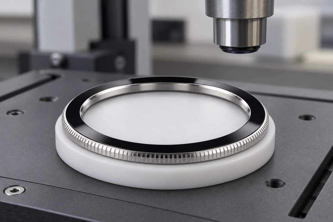
세라믹 표면이 스크래치에 강하더라도 모서리에 충격이 집중되면 치핑이나 균열이 발생할 수 있습니다. 단품의 평면 압축 시험만으로 착용 중 충돌을 설명하기 어렵습니다. 완성 조립체의 지지 조건과 충돌 위치를 정하고, 초기 외관뿐 아니라 시험 후 균열·이탈·단차 변화를 확인합니다.
| 평가 축 | 시험으로 분리할 질문 | 함께 기록할 항목 |
|---|---|---|
| 온도 변화 | 팽창·수축의 반복으로 접합부 손상이나 위치 변화가 누적되는지 확인합니다. | 온도 상·하한, 전이 속도, 유지시간, 횟수와 실제 시편 온도를 기록합니다. |
| 습도·오염물 노출 | 수분, 땀이나 세정 환경이 접합부와 금속 표면에 미치는 영향을 확인합니다. | 용액 조성·농도, 온도, 시간, 건조·세정 절차와 평가 시점을 정합니다. |
| 충격·낙하 | 외주·모서리·면 충돌에서 파손 위치와 이탈 경로를 확인합니다. | 질량, 조립 상태, 충돌 자세·표면·높이와 관찰 방법을 기록합니다. |
| 당김·비틀림 | 세라믹–금속 내부와 베젤링–워치 장착면 중 어느 경계가 약한지 분리합니다. | 하중 방향·속도, 고정 지그, 변위와 파단면을 연결합니다. |
| 노화 후 재평가 | 초기 합격품이 환경 노출 후에도 같은 기능을 유지하는지 확인합니다. | 시험 순서, 대조 시편과 잔존 강도·외관·치수 변화를 비교합니다. |
접착 시험에서 얻은 파괴 하중은 파단 위치와 함께 읽습니다. 접착제가 한쪽 표면에서 떨어지는 계면 파괴, 접착층 내부에서 갈라지는 응집 파괴, 코팅의 박리와 세라믹 자체 파손은 서로 다른 개선을 요구합니다. 파괴 하중이 높아졌더라도 세라믹 파손이 늘었다면 접합부가 구조적으로 개선되었다고 곧바로 판단할 수 없습니다.
온도 변화와 습열 시험은 관련 표준의 방법을 활용하되 실제 용도에 맞는 조건을 지정합니다. 시험 방법의 이름만으로 제품의 수명, 방수 등급이나 인체 접촉 안전성이 입증되지는 않습니다. 특히 장식용 베젤링의 부착과 워치 본체의 방수 씰은 다른 기능입니다. 베젤링의 접착 강도를 워치 방수 성능으로 바꾸어 설명하지 않습니다.
갈바닉 부식과 틈 환경의 구분
통상적인 절연성 산화물 세라믹과 스테인리스의 조합을 알루미늄–스테인리스 같은 두 금속의 갈바닉 쌍으로 바로 다루지는 않습니다. 다만 실제 세라믹의 전기적 특성, 전도성 장식층과 주변 금속을 확인해야 합니다. 금속 표면의 좁은 틈에 염분과 수분이 오래 남는 문제는 별도로 평가합니다. 316L이라는 재료명만으로 모든 틈부식이나 표면 변색이 배제되지는 않습니다.
8. 양산 사양을 완성하는 도면과 승인 조건
개발 사양에는 세라믹의 재질·등급, 금속의 규격과 공급 상태, 각 부품의 기준면과 최종 마감을 연결합니다. 여기에 접합 영역, 허용 간극, 경화 후 층 두께, 눈금 기준 방향과 외관 허용 기준을 표시하면 가공·표면처리·조립 업체가 같은 목표를 확인할 수 있습니다.
조립품 승인에는 가장 잘 맞는 한 쌍만 사용하는 대신 부품 공차의 분포와 로트 차이를 반영합니다. 최소 간극 조합, 최대 간극 조합과 높이 차이가 큰 조합을 검토하면 평균치 조립에서 발견하기 어려운 문제를 확인할 수 있습니다. 설계 변경 시에는 세라믹 공급원, 표면처리, 접착 재료와 경화 조건 중 무엇이 바뀌었는지 추적하여 재검증 범위를 정합니다.
세라믹 베젤링의 정밀도는 작은 틈을 없애는 데서 끝나지 않습니다. 외관상 일정한 경계, 손상을 만들지 않는 조립, 사용 온도에서의 변형 여유와 충격 후의 유지 성능이 함께 충족되어야 합니다. 이 조건들을 연결한 설계가 두 소재의 장점을 얇은 웨어러블 외장 안에 안정적으로 담아냅니다.
English edition
Ceramic bezel rings: stainless-steel support, thermal expansion and impact design
A glossy ceramic ring and a thin stainless-steel support form a compact exterior assembly. Its quality depends on more than the appearance of either material. Clearances and joining interfaces must accommodate their different deformation while preserving a uniform visible boundary.
An uneven gap or height step makes the entire ring appear misaligned. Reducing the clearance too far can chip a ceramic edge during assembly, while an uneven joining layer changes where thermal and impact loads are transferred. Dimensional tolerances, layer thickness, edge geometry and assembly sequence therefore belong to the same structural design problem.
1. The respective roles of ceramic and 316L stainless steel
PERSLOT ceramic–metal bezel rings for Galaxy Watch6 and the G-style G-1 and G-2 rings for Galaxy Watch7 illustrate this combination of materials. The Watch6 product information identifies ceramic and stainless steel, while the metal in the G-1 and G-2 specifications is labelled Stainless Steel 316L. The material designation used here is therefore 316L.
Ceramic is not a metal, so this is a dissimilar-material assembly. Its hardness, fracture toughness, thermal expansion and surface quality depend on ceramic composition and on sintering and finishing. A black appearance does not establish whether a component is zirconia or alumina, nor does it establish a hardness value.
| Component | Design contribution | Associated limitation |
|---|---|---|
| Ceramic upper ring | Suitable compositions and finishes can provide a hard surface and consistent gloss. | Hardness does not guarantee impact resistance. Edge defects and local tensile stresses influence fracture. |
| 316L support | Thin shoulders, mounting faces and an outer profile can be machined to locate the ring and distribute loads. | Thin sections can distort under fixturing or external forces. Corrosion resistance also depends on surface condition and exposure. |
| Joining interface | The joint retains alignment and transfers loads. Depending on its design, it can also accommodate differential movement. | Material names alone do not determine joint strength. Interface condition, thickness, cure, geometry and environmental history all matter. |
G-1 and G-2 appearance and published dimensions
Both styles have a black upper annulus, a silver boundary and repeated vertical grooves around the outside. Their numeral and marker layouts differ: G-1 uses broad numeral blocks and bar markers, while G-2 uses minute numerals with dots and lines. These markings establish a visible angular reference, so assembly must control rotational alignment as well as radial centring.
The published specifications for the versions corresponding to 40 mm and 44 mm watches give outside diameters of 40.6 mm and 44.6 mm, inside diameters of 33.3 mm and 37.3 mm, a thickness of 2.9 mm, and a “2 Layered” construction. These are finished-bezel dimensions, not pocket-fit dimensions or joining-layer thicknesses. The accompanying PVD Coating designation also does not identify the internal ceramic-to-metal joining process.
2. The internal joint and the watch-mounting interface
A bezel can have two different attachment interfaces. One joins the ceramic upper part to its metal support. The other attaches the completed bezel to the watch. The replacement double-sided tape shown in the product information belongs to the latter interface; it does not establish that the same tape joins the ceramic and steel internally.
Within the bezel, the supporting face, radial locating features and joining layer share the load. At the watch interface, fit, contact area, cleanliness and removal conditions become important. If a bezel separates in use, identifying the failed interface is the first step toward selecting an effective correction.
The supporting shoulder and joining layer in the interactive model are design concepts for explaining these relationships. They do not reproduce an undisclosed production cross-section. The exploded view separates the ceramic ring, metal support and joining region; the assembled view shows their visible boundary and support positions.
Separating support from location
A broad annular seat can distribute axial loads over several regions. A few isolated high points can instead produce local bending in the ceramic. Similarly, forcing a metal shoulder directly against a sharp ceramic edge can turn a small assembly error into a high contact stress.
Accurate location does not require every face to be tightly constrained at once. One option is to establish axial height through a datum seat and a controlled joining layer, while using clearance and an alignment fixture to manage radial position. Whether retention is mechanical, adhesive or a combination, the load path during assembly must be defined first.
3. Differential thermal expansion and assembly clearance
Two components at the same temperature can expand by different amounts when unconstrained. In an annular assembly, even a small difference in expansion coefficient interacts with restraint around the circumference. The relevant properties are those of the actual material grades over the intended temperature interval.
Many zirconia and alumina ceramics expand less than common austenitic stainless steels, but the difference depends on the materials. Average coefficients measured over different temperature ranges should not be combined as though they provide a precise prediction. In a joined assembly, elastic stiffness, the joining layer’s viscoelastic response, geometry and cure history also affect the resulting stress.
ΔD = D · (αm − αc) · ΔT
D is the reference diameter; αm and αc are the metal and ceramic linear expansion coefficients; ΔT is the temperature change from the reference state. This estimates the difference in free diameter change when the reference diameters are similar and the coefficients are treated as constant.
Illustrative design calculation: assuming D = 40 mm, a coefficient difference of 6 × 10⁻⁶/K and ΔT = 60 K gives a diameter-change difference of 0.0144 mm, or 14.4 μm. The corresponding radial difference is 7.2 μm. These are assumed-model results, not product measurements or recommended assembly clearances.
Opposite effects at an outer pocket and an inner core
If a metal pocket surrounds the ceramic outside diameter and the metal has the higher expansion coefficient, heating tends to increase the outer clearance. Cooling tends to reduce it. If a metal core instead sits inside the ceramic bore, heating can reduce the inner clearance as the core expands more.
An annular pocket with both inner and outer metal shoulders therefore requires separate checks at the two boundaries. One side can gain clearance while the other becomes more constrained. Where a joining layer connects the parts, free-expansion mismatch is shared between layer deformation, component deformation and stress rather than appearing entirely as a gap change.
Cure temperature also belongs in the reference conditions. An assembly bonded at an elevated temperature can acquire residual deformation as it cools before use. Chemical cure shrinkage and differential thermal contraction are separate effects; a thermal-expansion calculation alone does not describe both.
4. Diameter, roundness and flatness in the tolerance chain
Matching average diameters does not create equal clearance at every angular position. Ovality, radial runout, seat distortion and burrs can make one region contact first. On a ceramic ring, such line or point contact can concentrate assembly loads.
For an ideal concentric circular geometry, let Dp be the pocket inside diameter and Dc the ceramic outside diameter. The radial outer clearance is gr = (Dp − Dc)/2. Combining the smallest pocket with the largest ceramic diameter evaluates the minimum dimensional clearance. Local interference caused by form and position errors, surface treatment and temperature change must then be checked separately.
| Characteristic | Potential manifestation | Linked drawing and assembly controls |
|---|---|---|
| Diameters and roundness | A tight region can coexist with an excessive gap elsewhere. | Define inspection datums and temperature, then measure dimensions and form around the circumference. |
| Seat flatness | One region contacts first while another remains raised. | Connect seat machining, deburring, layer uniformity and fixture parallelism. |
| Height and step | The reflected boundary between black ceramic and silver metal becomes uneven. | Control ceramic thickness, pocket depth and cured joining-layer thickness as one dimensional chain. |
| Reference orientation | Markers rotate out of alignment, or the visible centre differs from the functional centre. | Define both centres and a separate angular reference for the markings. |
| Edge radius and chamfer | Chipping can occur at the insertion edge, bore or lower rim. | Provide insertion guidance and stress relief while checking interference with the mating component. |
In the enlarged section, gr represents radial clearance, tb the joining-layer thickness, H the pocket depth and Rc the edge geometry. These symbols identify design variables without assigning undisclosed product dimensions. Thin layers and small gaps are enlarged to make their relationships visible.
Final dimensions after surface treatment
Dimensions immediately after machining may differ from those at assembly. Polishing removes material and changes edges; coating adds a surface layer. Functional pockets, seats and bonding regions must therefore be controlled in their final treated condition. Finishing the visible surface does not require every hidden bonding face to receive the same mirror polish.
5. Defining loads and movement before selecting a joining layer
If adhesive bonding is selected, room-temperature shear strength alone is insufficient for material selection. Torsion, edge-lifting peel and cyclic shear from temperature changes are different loading modes. Equal nominal bonding areas can behave differently when a force is concentrated at one edge rather than distributed around the circumference.
A thin, stiff layer can support positional accuracy but may offer limited accommodation of differential movement. A more compliant layer can reduce stress concentration, yet may permit greater creep or reduce long-term positional stability. Thickness and mechanical response must be selected together with the adhesive’s stated application conditions, cure state and tests on the actual joint geometry.
γ ≈ Δu / tb
This elementary relation treats the relative displacement Δu between the layer faces as simple shear across thickness tb. It shows why the same movement produces greater shear strain in a thinner layer. It is not a prediction of annular-joint end stress or service life.
Interface cleanliness and appearance
Polishing compounds, cutting fluids, release agents and handling contamination can remain on apparently clean surfaces. Prevent recontamination after cleaning and control the delay and storage conditions before bonding. Surface activation or primers require compatibility with the adhesive, ceramic, metal and any coating. Greater roughness does not automatically produce a stronger joint, and aggressive treatment of a ceramic bonding face can introduce defects.
If a PVD layer is present in the joining area, distinguish adhesive-to-coating adhesion from coating-to-substrate adhesion. An effective decorative coating is not automatically a suitable bonding surface. Masking or separate pretreatment of the joining area may be considered, with the visible boundary and corrosion requirements evaluated together.
Dispensing, cure and rework
Adding adhesive does not necessarily increase the effective bonded area. Excess material can overflow onto the ceramic face or migrate inward, while too little can leave discontinuous regions. Dispensing path and quantity, component placement speed, air escape and alignment during cure must be controlled as a connected process.
Where spacers or geometry establish layer thickness, verify that hard particles or protrusions do not introduce point loads into the ceramic. Distinguish fixture-release time from complete cure. If removal or rework is required, assess the effects of heat and solvents on the ceramic surface, metal coating and underlying mounting material.
6. Manufacturing separate parts for a precise exterior assembly
The ceramic and metal parts require different manufacturing sequences. The ceramic ring is formed through the chosen material and sintering route; functional surfaces can then be finished by diamond grinding and polishing where needed. Shrinkage and sintering temperature depend on the material and process. A single generic value cannot represent every ceramic.
The metal support starts with a process suited to its stock form and production quantity, followed by precision machining of the annular pocket and datum surfaces. Heavy clamping can make a thin ring measure correctly while held but return toward an oval shape after release. Support, machining sequence and final cutting allowance must account for the difference between restrained and free states.
Ceramic edges and metal burrs
A small ceramic chip is both a cosmetic defect and a possible origin for later fracture. Control grinding direction, tool condition and support, and inspect the inner, outer and lower edges before assembly. A small burr in the metal pocket can likewise prevent full seating or create a local contact that scratches the ceramic.
Forcing a part into position by hand can conceal the cause of resistance. Increased force applied to an interference condition may produce an assembly that appears normal despite hidden damage. Relate assembly-force changes to seating and visible step height, then investigate dimensions, burrs, dispensing and fixtures separately when an abnormality appears.
Controlling appearance and function together
The boundary between glossy ceramic and polished metal changes visually with the lighting angle. Rotate the assembly when checking boundary width and height rather than relying on one lighting direction. Inspect marker orientation, groove regularity and adhesive residue under consistent conditions. After mounting, separately check that the bezel does not obstruct buttons, the screen edge or other designated functional areas.
7. Linking impact, temperature, humidity and use-environment tests
Scratch resistance does not prevent chipping or cracking when impact is concentrated at a ceramic edge. A flat compression test on an isolated part does not represent every collision during wear. Define support conditions and impact locations for the complete assembly, then inspect cracks, separation and step-height changes after testing.
| Evaluation | Question to resolve | Conditions to record |
|---|---|---|
| Temperature change | Does repeated expansion and contraction accumulate joint damage or positional change? | Temperature limits, transition rate, dwell, cycles and actual specimen temperature. |
| Humidity and contaminants | How do moisture, perspiration or cleaning exposure affect the joint and metal? | Solution composition and concentration, temperature, duration, drying and cleaning procedures, and evaluation timing. |
| Impact and drop | Where do fracture and separation occur under outer-edge, corner or face impacts? | Mass, assembly state, orientation, impact surface, drop height and observation method. |
| Pull and torsion | Is the limiting interface inside the bezel or between bezel and watch? | Load direction and rate, fixture support, displacement and fracture surfaces. |
| Post-ageing evaluation | Does an initially acceptable assembly retain its function after exposure? | Test sequence, control specimens, retained strength, appearance and dimensional changes. |
Interpret failure load together with the fracture location. Separation from a surface, cohesive failure within the joining layer, coating delamination and ceramic fracture require different corrective actions. A higher measured load accompanied by more ceramic breakage does not, by itself, establish that the assembly has improved.
Temperature-change and humidity testing can use relevant standardized methods, but the conditions must match the intended application. A test-method name alone does not establish service life, water resistance or suitability for skin contact. In particular, a decorative bezel attachment and the watch’s pressure-sealing system serve different functions. Bezel bond strength must not be presented as watch water-resistance performance.
Galvanic effects and retained moisture in crevices
A conventional electrically insulating oxide ceramic joined to stainless steel is not automatically equivalent to an aluminium–stainless galvanic couple. The actual ceramic’s electrical properties, conductive decorative layers and nearby metals still need to be identified. Salt and moisture retained in a narrow region of the metal surface present a separate concern. The 316L designation does not exclude all crevice corrosion or discoloration.
8. Drawings and approval conditions for production
A complete specification connects the ceramic grade, metal standard and supply condition with the datums and final finish of each part. Joining regions, permitted clearances, cured layer thickness, marker orientation and cosmetic acceptance limits give machining, finishing and assembly teams a common target.
Assembly approval should reflect part distributions and lot variation rather than only a particularly well-matched pair. Minimum-clearance, maximum-clearance and adverse height combinations can reveal problems missed by assemblies at average dimensions. When a ceramic source, surface treatment, joining material or cure condition changes, trace that change and define the corresponding revalidation scope.
Precision in a ceramic bezel ring is more than the elimination of a small visible gap. A uniform boundary, damage-free assembly, adequate movement accommodation over the use-temperature range and retention after impact must be achieved together. Their coordinated design allows both materials to contribute within a thin wearable exterior.
추가 정보
세라믹 베젤링의 사양 정리와 불량 진단
세라믹–스테인리스 결합에서 외관, 치수와 내구성은 같은 접합부를 서로 다른 관점에서 평가한 결과입니다. 소재와 가공품을 각각 승인한 뒤, 실제 조립 상태에서 경계 폭·단차·유지 성능을 확인합니다.
개발 도면과 함께 전달할 조건
| 분류 | 필요 정보 |
|---|---|
| 소재·형상 | 세라믹 조성·등급, 금속 규격, 부품 내·외경, 두께, 모서리 형상과 기준면을 연결합니다. 완성품 외형 치수와 내부 끼워맞춤 치수는 구분합니다. |
| 외관·접합면 | 광택·색·눈금 방향, 노출 경계의 허용 상태, 접착 영역과 코팅·마스킹 범위를 표시합니다. |
| 조립·사용 조건 | 위치 결정 방식, 조립력, 접합층 제어, 경화와 취급 시점, 온습도·충격·세정 환경을 정합니다. |
| 승인·추적 | 초기 및 환경 노출 후의 합격 기준, 검사 지그, 소재·표면처리·접합재 로트와 변경 승인 절차를 연결합니다. |
증상별 원인 분리
한쪽만 들뜹니다. 받침면 휨, 버, 국부 간섭, 도포량과 경화 지그의 기울기를 순서대로 확인합니다. 더 큰 힘으로 누르기 전에 접촉 위치를 조사합니다.
세라믹 모서리가 깨집니다. 손상 위치와 방향을 기록하고 조립 전 치핑, 금속 턱 간섭, 점하중과 후속 충격을 구분합니다. 접착 강도만 올리는 조치가 원인을 해결하지 못할 수 있습니다.
환경 시험 뒤 분리됩니다. 파단면에서 계면 파괴·응집 파괴·코팅 박리·세라믹 파손을 구분합니다. 세정, 전처리, 경화와 수분·열 이력을 연결해 조사합니다.
눈금이나 경계가 어긋납니다. 중심 위치 오차와 회전 방향 오차를 따로 측정합니다. 반사 때문에 생기는 시각적 차이는 조명과 관찰 방향을 맞춰 다시 확인합니다.
계산과 시험 결과를 읽는 기준
열팽창 예시의 14.4 μm는 가정한 두 부품의 자유 직경 변화 차이입니다. 한쪽 반경 차이는 그 절반이며 실제 필요한 간극이나 접합층 두께를 직접 정하는 값이 아닙니다. 환형 구조에서 안쪽과 바깥쪽 경계의 구속 방향도 따로 확인합니다.
평판 겹침 시편의 전단강도에 베젤 면적을 곱해 이탈력을 확정하지 않습니다. 하중 방향·끝단 응력·피착재·표면처리와 실제 제품 형상이 다르기 때문입니다. 가속 노화의 시간도 검증된 상관관계 없이 사용 연수로 바꾸지 않습니다.
자주 확인하는 기술 사항
세라믹과 금속은 반드시 접착제로 조립합니까?
기계적 고정, 접착, 복합 구조 등 여러 방식이 가능합니다. 실제 적용 방식은 도면과 공정 자료로 확인해야 하며 외관만으로 확정할 수 없습니다.
세라믹 경도가 높으면 충격에도 강합니까?
경도와 파괴인성은 다른 물성입니다. 표면의 긁힘 저항과 모서리 충격·굽힘에 대한 파손 저항을 각각 평가합니다.
워치 장착용 테이프가 내부 소재 접합층입니까?
구분해야 합니다. 완성 베젤링을 워치에 부착하는 층과 세라믹–금속 사이의 내부 접합부는 위치와 역할이 다릅니다.
간극은 작을수록 유리합니까?
외관에는 유리할 수 있지만 공차 누적과 온도 변화로 국부 간섭이 생길 수 있습니다. 최대·최소 간극, 모서리 지지와 사용 환경을 함께 검토합니다.
316L과 세라믹이면 부식 검토가 필요 없습니까?
소재의 전기적 특성과 표면층을 확인하고, 금속 틈의 수분·염분 노출도 검토합니다. 일반적인 절연성 세라믹을 두 번째 금속으로 취급하지 않지만 주변 금속과 도전층은 별도 조건입니다.
접합 구조를 바꿨을 때 재시험 범위는 어떻게 정합니까?
소재, 표면처리, 형상, 접합재와 경화 중 바뀐 항목을 확인한 뒤 영향을 받는 외관·치수·환경·하중 시험을 선정합니다. 기존 승인품과 변경품을 같은 조건에서 비교합니다.
관련 기술 분야
CNC·MCT 가공 · 정밀선반가공 · 시계 방수와 접합 경계 · 제품문의
관련 태그

Related posts
명품 무브먼트 마감: 앵글라주·블랙 폴리싱·제네바 스트라이프의 정밀 제조
3축 가공과 5축 가공: 공구 접근·셋업·정밀도와 제조 원가 비교
외장 SSD 케이스: 알루미늄 방열 구조와 정밀가공 설계
알루미늄 외장 아노다이징 색차: 소재·표면·피막에서 조립 색상까지