알루미늄 외장 아노다이징 색차: 소재·표면·피막에서 조립 색상까지
ALUMINUM · ANODIZING · COLOR CONTROL
알루미늄 외장 아노다이징 색차:
소재·표면·피막에서 조립 색상까지
케이스와 버튼에 같은 색을 지정해도 조립하면 서로 다르게 보일 수 있습니다. 아노다이징 색차는 염료만의 문제가 아니라, 알루미늄의 조직과 가공면, 산화피막, 빛의 반사가 함께 만든 결과입니다.
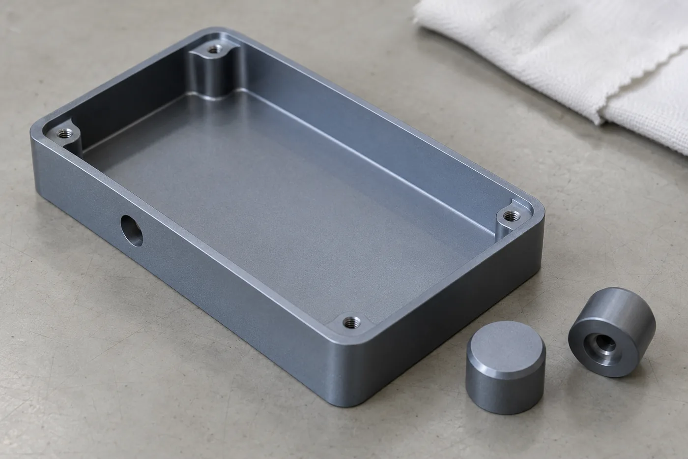
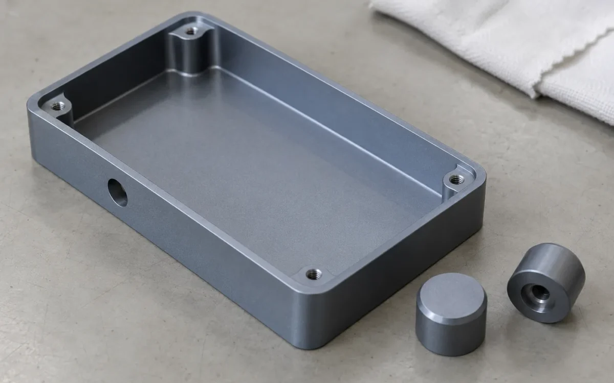
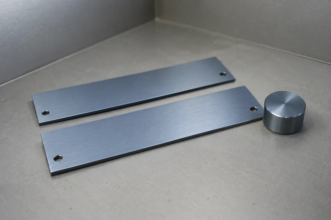
알루미늄 외장에서는 색상과 금속 질감을 따로 설계하기 어렵습니다. 같은 청색이라도 평평한 케이스는 차분하게 보이고, 둥근 노브는 밝은 띠가 나타납니다. 헤어라인 방향이 다른 덮개를 연결하면 한쪽만 어둡게 보이기도 합니다. 이런 차이를 전부 염색 불량으로 판단하면 정상 부품을 재작업하거나, 실제 원인을 남긴 채 염색 조건만 반복해서 조정하게 됩니다.
안정적인 색상 일치는 소재와 표면을 먼저 맞추고, 피막·착색·봉공을 관리한 뒤, 정해진 조명에서 단품과 조립품을 함께 평가하는 방식으로 확보합니다. 휴대용 오디오 케이스, 미용기기 알루미늄 외장, 조작 노브와 버튼처럼 가까이 배치되는 금속 부품에서 이 연결이 특히 중요합니다.
1. 금속의 바탕이 남는 아노다이징 색상
알루미늄 아노다이징은 전해 반응으로 표면에 산화피막을 성장시키는 공정입니다. 장식용 황산 아노다이징에서는 기재 가까이에 치밀한 장벽층이 형성되고, 그 위에 다공성 산화층이 발달합니다. 유기 염료로 착색하는 경우에는 다공성 구조에 염료가 흡착되고, 이후 봉공 공정으로 공극의 개방성을 줄입니다.
불투명한 도막으로 바탕을 가리는 방식과 달리, 아노다이징 외관에는 기재의 반사 특성과 표면 형상이 상당 부분 남습니다. 입사한 빛은 표면에서 반사·산란되거나 피막 내부로 들어가 흡수와 반사를 겪습니다. 따라서 염료의 색이 같아도 기재 조직, 표면 거칠기와 피막 상태가 달라지면 관찰되는 색과 광택이 달라질 수 있습니다.
착색 방식도 구분해야 합니다. 유기 염료 착색과 공극에 금속을 석출시키는 전해 착색은 반응과 관리 항목이 같지 않습니다. 경질 아노다이징의 자연 발색을 장식용 염색 색상과 동일하게 취급해서도 안 됩니다. 아래의 공정 설명은 주로 알루미늄 장식 외장의 황산 아노다이징과 염료 착색에 해당합니다. 스테인리스 MIM 부품의 PVD 코팅이나 티타늄 간섭색에는 그대로 적용하지 않습니다.
2. 색상 일치의 출발점: 합금·질별·소재 로트
알루미늄 합금의 구리, 규소, 마그네슘, 철 등은 기계적 성질뿐 아니라 전처리 반응과 산화피막의 외관에도 영향을 줍니다. 금속간화합물의 분포와 입자 상태는 에칭 후 표면과 빛의 산란을 바꿀 수 있습니다. 같은 합금 계열이라는 이유만으로 동일한 색을 보장할 수 없는 이유입니다.
케이스를 판재에서 깎고 노브를 봉재에서 선삭하면, 합금 번호가 같더라도 압연·압출 방향과 조직, 열처리 이력이 다를 수 있습니다. 질별은 이러한 가공·열처리 상태를 나타내는 구분입니다. 소재 성적서에는 합금명만 확인하는 대신 질별, 공급 형태와 로트를 함께 연결해야 합니다.
| 소재 조건 | 외관에 연결되는 문제 | 개발 단계의 판단 |
|---|---|---|
| 5000·6000계 전신재 | 장식용 외장에 활용되지만 합금·질별과 조직에 따라 에칭 및 반사 상태가 달라집니다. | 후보 소재의 실제 가공품을 같은 공정으로 처리해 색과 질감을 비교합니다. |
| 2000·7000계 전신재 | 강도를 위해 선택한 합금이 피막 외관과 착색 재현성에 추가 제약을 줄 수 있습니다. | 필요 강도와 외관 목표를 함께 검토하며, 다른 계열 부품과의 색 일치를 별도로 승인합니다. |
| 규소 함량이 높은 주조재 | 기지와 규소상의 반응 차이, 주조 조직과 표면 상태가 얼룩·회색조 등에 영향을 줄 수 있습니다. | 전신재와 같은 색 번호만 지정하지 않고 공법별 승인 시편을 만듭니다. |
| 동일 규격의 공급 로트 변경 | 허용 조성 범위와 조직, 전처리 반응의 차이가 외관으로 나타날 수 있습니다. | 입고 로트부터 가공·표면처리 로트까지 추적합니다. |
부품의 기능 때문에 소재를 통일할 수 없다면, 처음부터 서로 다른 소재를 같은 색으로 맞추는 개발 과제로 취급합니다. 한 부품의 염색 조건을 다른 부품에 그대로 복사하는 대신, 실제 조립 외관을 기준으로 각 공정의 허용 범위를 좁혀야 합니다. 용접부나 국부 열영향부가 있는 외장도 모재와 함께 평가합니다.
3. 가공면과 전처리가 만드는 밝기·광택의 차이
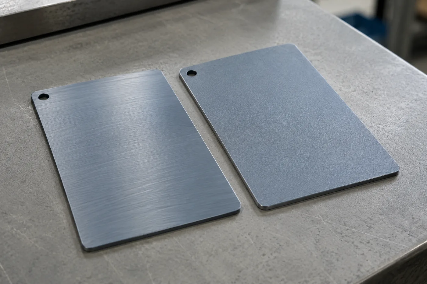
선삭면의 동심원과 밀링면의 이송 자국은 방향성을 가진 반사를 만듭니다. 헤어라인은 관찰 방향에 따라 밝은 반사 띠가 움직이고, 블라스팅은 미세한 요철로 빛을 분산시킵니다. 같은 색을 입혀도 표면을 만드는 방식이 다르면 외관은 일치하지 않을 수 있습니다.
조도 값 하나로 표면을 규정할 수 없는 이유
Ra가 같아도 자국의 간격, 봉우리 형태와 방향성이 다르면 빛의 산란은 달라집니다. 따라서 외장 도면에는 필요한 거칠기 항목과 함께 헤어라인 방향, 광택 또는 비교 시편을 지정하는 편이 유효합니다. 블라스팅은 연마재 종류·입도·사용 상태, 분사 압력·거리·각도·처리 시간을 관리합니다. 이를 통제하지 않으면 같은 무광이라는 표현 아래 서로 다른 표면이 섞입니다.
거친 표면이 항상 더 밝거나 옅게 보이는 것은 아닙니다. 반사·산란과 흡수의 조합은 색상, 관찰 조건과 표면 구조에 따라 달라집니다. 개발 시편에서는 색차 수치뿐 아니라 광택과 결 방향을 함께 확인해야 원인을 구분할 수 있습니다.
탈지·에칭·디스머트의 역할 분리
탈지는 가공유와 오염을 제거하고, 에칭은 표면을 용해시켜 외관을 조정합니다. 합금에 따라 에칭 후 남는 잔류물은 디스머트 등 적합한 후속 전처리로 제거합니다. 오염을 남긴 채 염색 시간을 늘려도 얼룩의 근본 원인은 해결되지 않습니다.
에칭 시간만 길게 설정하는 방식도 주의가 필요합니다. 소재 조직의 차이가 더 드러나거나, 날카로운 모서리와 미세 형상이 변할 수 있습니다. 가공 자국을 어느 단계에서 제거할지 먼저 정하고, 기계 연마와 화학 전처리의 역할을 분담합니다. 얇은 버튼과 두꺼운 케이스는 같은 처리 시간이라도 외관과 치수의 허용 여유가 다를 수 있습니다.
평면과 원통면은 같은 빛 아래에서도 반사 조건이 다릅니다. 조립 검토에서는 각 부품을 따로 정면에서 보는 평가와, 실제 장착 방향으로 함께 보는 평가를 병행합니다. 3D의 조명·결 방향 변화는 이 기하학적 관계를 살펴보기 위한 것으로, 실제 피막의 분광 특성이나 측색값을 예측하지 않습니다.
4. 산화피막: 두께와 공극 상태를 함께 관리
피막 두께는 착색과 내구성을 연결하는 중요한 변수지만, 두께가 같다는 사실만으로 동일한 색이 보장되지는 않습니다. 전해액의 상태, 온도, 전류 조건과 처리 시간은 피막 성장과 용해에 관여합니다. 그 결과 공극 구조와 염료 흡착 조건도 달라질 수 있습니다.
두께를 늘리면 색이 항상 일정하게 진해진다는 단순한 규칙은 성립하지 않습니다. 바탕의 반사, 공극 구조, 염료와 착색 상태가 함께 작용하기 때문입니다. 지정된 두께 범위에서 원하는 색과 봉공 품질을 재현할 수 있는지를 실제 소재와 형상으로 확인해야 합니다.
위 단면은 장벽층, 다공성 산화층과 착색·봉공의 관계를 확대한 개념 구조입니다. 실제 공극의 크기와 층의 비율을 표현한 축척 모형은 아닙니다. 열수 봉공에서는 산화물의 수화와 구조 변화가 공극을 좁히는 데 관여하며, 다른 봉공 방식은 반응과 관리 조건이 달라집니다.
전류 분포와 치구 접점
피막 형성에는 안정적인 전기 접촉이 필요합니다. 접점은 외관 허용 구역과 조립 구조를 고려해 정하고, 접촉 불량이나 과도한 국부 전류를 방지해야 합니다. 랙의 적재량, 부품 간격과 방향, 교반 및 기포 배출 조건도 형상별로 검토합니다.
깊은 포켓이나 막힌 홈은 평평한 외관면과 액 교환 조건이 다릅니다. 내부까지 동일한 색과 두께를 요구할 경우에는 외관면과 다른 공정 난점이 생길 수 있습니다. 도면에서 주요 외관면, 기능면과 비가시 영역을 구분하면 필요 이상의 요구를 줄이면서 중요한 영역을 집중 관리할 수 있습니다.

5. 염색·수세·봉공: 최종 색은 건조 후 승인
염색에서는 염료 종류와 농도, pH, 액 온도, 처리 시간뿐 아니라 욕의 오염과 수명, 피막 상태를 함께 관리합니다. 염색 시간은 색 조정 수단의 하나입니다. 전처리나 피막 형성의 변동을 염색 시간 하나로 보상하려 하면 다른 로트에서 다시 차이가 발생하기 쉽습니다.
검정색도 예외가 아닙니다. 사용 염료와 피막·공정에 따라 적색이나 청색 계열의 잔색감이 달라질 수 있습니다. 어두운 색이라는 이유로 색차 관리를 생략하면 케이스와 버튼이 맞닿는 경계에서 차이가 두드러질 수 있습니다.
공정 사이 수세는 다음 욕으로의 오염물 유입을 줄이는 역할을 합니다. 이후 봉공 조건은 염료 유지와 표면 상태에 영향을 주며, 부적절한 조건은 외관의 흐림이나 잔류물 문제로 이어질 수 있습니다. 색을 승인할 때에는 봉공 직전의 젖은 상태가 아니라 합의한 건조·안정화 조건을 거친 최종 상태를 사용합니다.
맞춰진 초기 색과 장기 내광성·내식성·내마모성은 별도의 성능입니다. 필요 사용 환경에 따라 색 유지, 땀·세정제 접촉과 마찰 등을 검토하되, 초기 ΔE가 작다는 이유만으로 내구 시험을 통과한 것으로 해석하지 않습니다. 봉공 품질 역시 색측정만으로 판정하지 않습니다.
6. 색상 사양과 함께 정해야 하는 형상·치수
아노다이징은 기재를 소모하면서 피막을 형성하므로 원래 금속 표면의 안쪽과 바깥쪽에 걸쳐 성장합니다. 전처리의 소재 제거와 피막의 외향 성장량을 함께 고려해야 최종 치수를 예측할 수 있습니다. 총 피막 두께를 그대로 외형 증가량으로 더해서는 안 됩니다.
특히 노브의 축 끼워맞춤, 버튼 가이드 구멍과 정밀 나사는 피막 처리 후 기능 치수가 중요합니다. 필요한 마스킹 위치, 처리 전 가공 여유와 처리 후 검사 기준을 정합니다. 일반 아노다이징 피막은 전기 절연성이 있으므로, 접지 접촉면이나 전기적 연결부를 외관면과 같은 방식으로 처리할 수 있는지도 검토합니다.
| 설계 요소 | 도면에 연결할 항목 | 검토 이유 |
|---|---|---|
| 케이스와 덮개의 접합선 | 조립 방향, 헤어라인 방향, 인접 부품 조합 | 같은 색이라도 결 방향과 반사 조건이 다르면 경계가 강조됩니다. |
| 원형 노브·작은 버튼 | 측정 가능한 평면, 지그 기준, 실물 외관 승인 | 곡률과 작은 면적으로 인해 케이스 평면과 측색 조건이 달라집니다. |
| 모서리·미세 홈·문자 | 전처리 허용 변화, 보호 영역, 최종 형상 | 가공·연마·에칭의 누적 영향으로 디테일이 달라질 수 있습니다. |
| 치구 접점과 배액 | 접점 허용 위치·범위, 걸이 방향, 액 고임 방지 | 전기 접촉과 수세·건조를 확보하면서 노출면 흔적을 줄입니다. |
| 끼워맞춤·전기 접촉면 | 처리 후 치수, 마스킹, 필요 접촉 저항 | 외관 요구와 조립·전기 기능이 충돌하지 않도록 합니다. |
재박리와 재아노다이징도 무제한의 수정 수단이 아닙니다. 박리와 재전처리에서 소재가 추가로 제거되고, 거칠기와 모서리 형상이 바뀔 수 있습니다. 정밀 외장은 색상 재작업을 승인하기 전에 최소 벽 두께, 나사·끼워맞춤 치수와 허용 재작업 횟수를 확인해야 합니다.
7. 아노다이징 색차 측정: ΔE 앞에 측정 조건
색차계와 분광측색계는 정해진 광학 조건에서 색을 수치화합니다. CIELAB의 L*는 명도, a*는 녹색–적색 축, b*는 청색–황색 축입니다. 기준 시편과 제품 사이의 ΔL*, Δa*, Δb*를 함께 보면 단순히 차이가 크다는 판단을 넘어 어느 방향으로 변했는지 파악할 수 있습니다.
ΔE*ab와 ΔE00의 구분
ΔE*ab는 세 좌표 차이의 유클리드 거리입니다. 계산은 직관적이지만 같은 수치가 모든 색 영역에서 동일한 시각 차이를 뜻하지는 않습니다. CIEDE2000에 따른 ΔE00는 명도·채도·색상 차이의 가중 등을 반영하는 별도의 색차식입니다. 두 값을 고정 비율로 환산하거나, 한 식의 합격선을 다른 식에 그대로 적용하지 않습니다.
ΔE*ab = √[(ΔL*)² + (Δa*)² + (Δb*)²]
검사 규격에는 색차식, 기준 광원, 표준 관찰자, 측정 기하, 정반사 포함 여부와 측정 구경을 함께 기록합니다. ΔE00를 사용하는 경우에는 적용한 파라미터 조건도 일치시킵니다.
SCI·SCE와 45°:0°의 의미
적분구 방식의 SCI는 정반사 성분을 포함하고, SCE는 이를 제외합니다. SCI는 광택·질감의 영향을 줄여 색을 비교하는 데 유용하고, SCE는 표면 외관 변화에 더 민감할 수 있습니다. 그러나 어느 한 방식이 모든 금속 외장의 정답은 아닙니다. 제품의 광택·방향성과 검사 목적에 맞춰 측정 조건을 정하고 유지합니다.
45°:0°와 d:8°처럼 조명·관찰 기하가 다른 장비의 수치를 같은 기준으로 바로 비교해서도 안 됩니다. 기하 조건과 정반사 취급 방식이 함께 달라질 수 있습니다. 금속 헤어라인은 부품의 회전 방향에 따라서도 반응이 달라지므로, 기준 방향을 표시하거나 합의한 여러 방향에서 평가합니다.
측정 구경보다 작은 버튼, 모서리가 포함된 면, 곡면에서는 틈으로 빛이 새거나 다른 면이 함께 측정될 수 있습니다. 지그로 위치와 기울기를 반복 가능하게 만들고 측정 반복성을 먼저 확인합니다. 동행 평판 시편은 공정 추세를 보는 보조 수단이며, 실제 곡면 부품의 조립 외관을 대신하지 않습니다.
조명 변화와 메타머리즘
한 광원에서 비슷한 두 부품이 다른 광원에서 달라 보일 수 있습니다. 두 시료의 분광 반사 특성 차이로 광원에 따라 일치 관계가 변하는 현상은 메타머리즘과 관련됩니다. 다만 헤어라인 방향이나 곡률 때문에 반사 띠가 달라지는 현상까지 모두 메타머리즘이라고 부르지는 않습니다.
색 승인에는 합의한 기준 광원과 실제 사용 환경을 대표하는 추가 조명을 활용합니다. 시편의 방향·거리, 주변의 중성 배경과 관찰 위치를 일정하게 합니다. 휴대폰 자동 노출·화이트밸런스가 적용된 사진은 기록에 유용하지만, 그 사진만으로 최종 색상을 승인하지 않습니다.
8. 기준 시편에 맞추는 관리와 부품끼리 맞추는 관리
단품을 각각 기준 시편과 비교하는 것만으로는 조립 색상 일치를 충분히 관리하지 못할 수 있습니다. 한 부품이 기준보다 밝고 다른 부품이 기준보다 어두우면 두 부품 사이 차이는 커집니다. 가까이 붙는 케이스와 버튼, 전면 패널과 노브에는 기준 시편 대비 차이와 인접 부품 간 차이를 함께 검토합니다.
가상 CIELAB 좌표를 사용한 계산 예시
기준 M = (50.0, 0.0, −20.0)
케이스 A = (50.8, 0.6, −20.0)
버튼 B = (49.2, −0.6, −20.0)
A–M과 B–M의 ΔE*ab는 각각 √(0.8² + 0.6²) = 1.0입니다. 그러나 A–B는 √(1.6² + 1.2²) = 2.0입니다. 이는 색차의 방향을 설명하는 계산이며, 실제 측정 결과나 제품 합격 기준이 아닙니다.
같은 ΔE라도 명도 방향의 차이인지, 적색·청색 방향의 차이인지에 따라 조립품 인상이 달라집니다. 총 색차와 함께 좌표별 변화, 광택과 결 방향을 기록하면 로트가 어느 쪽으로 이동하는지 찾기 쉽습니다. 실제 합격 범위는 해당 제품의 형상, 색상과 사용 조건에서 시각 평가와 측정 반복성을 확인해 구매자와 공급자가 합의합니다.
색 이름이나 화면의 RGB 값은 개발 목표를 전달하는 출발점입니다. 양산 승인에는 최종 소재·표면·피막·봉공 조건으로 만든 실물 기준 시편과 허용 경계 시편이 더 적합합니다. 기준 시편은 오염·흠집·빛 노출에 따른 변화를 관리하고 식별 번호와 승인 이력을 남깁니다. 장기간 사용하는 작업용 시편과 보관용 기준을 구분하면 변화를 추적하기 쉽습니다.
9. 양산에서는 색차가 발생한 단계부터 좁혀갑니다
색차가 보이면 염색 욕부터 바꾸기 전에 변동이 어디에서 시작됐는지 확인합니다. 소재·전처리·산화피막·염색·봉공·관찰 조건이 동시에 바뀌면 인과관계를 찾기 어렵습니다. 동일 소재의 동행 시편과 공정 이력을 연결하고, 의심 변수를 나누어 비교합니다.
| 관찰된 현상 | 우선 비교할 조건 | 판단을 돕는 확인 |
|---|---|---|
| 로트 전체의 색이 이동합니다. | 소재 로트, 전처리 이력, 피막 두께, 염색·봉공 욕 상태 | 동일 측정 조건에서 기준 및 이전 로트의 좌표·광택 추세와 대조합니다. |
| 부품을 돌리면 차이가 크게 변합니다. | 헤어라인 방향, 가공 자국, 곡률, 조명·관찰 기하 | 방향을 맞춘 평면 비교와 실제 조립 방향의 관찰을 분리합니다. |
| 한 부품에 국부 얼룩이 있습니다. | 오염·수세, 액 고임, 접점, 국부 피막 및 봉공 상태 | 발생 위치를 랙 방향과 형상에 대응시켜 반복성을 확인합니다. |
| 봉공·건조 뒤 색이 달라집니다. | 봉공 조건, 잔류물, 수세·건조 및 관찰 시점 | 최종 상태 기준으로 동일 부품의 공정 전후를 비교합니다. |
| 단품은 비슷하지만 조립 경계가 보입니다. | 부품 간 좌표 차이, 광택, 결 방향과 소재 차이 | 기준 대비 차이와 실제 짝 부품 사이 차이를 함께 확인합니다. |
초도 검증에서는 시험편만 좋은 색을 얻는 것보다 실제 부품과 양산 랙에서 재현되는지를 보는 것이 중요합니다. 적재 위치와 시간, 소재 로트가 바뀌어도 공정이 허용 범위를 유지하는지 확인합니다. 케이스와 버튼을 같은 처리 로트로 묶는 방법은 공정 변동을 공유하게 하지만, 소재와 형상 차이를 없애지는 못합니다.
로트 선별로 일치하는 부품끼리 짝을 맞추는 방법은 제한적으로 활용할 수 있습니다. 다만 장기적으로는 재고와 교체 부품의 호환성을 어렵게 만들 수 있으므로, 선별에 의존하기 전에 소재와 표면·피막 조건을 안정화합니다. 승인 후 공급처·합금·전처리·염료·봉공 방식이 바뀌는 경우에는 변경 범위에 맞춰 다시 검증합니다.
10. 도면과 승인서에 남길 색상 사양
“청색 아노다이징”이라는 한 줄은 생산에 필요한 정보를 충분히 전달하지 못합니다. 외관색과 조립 품질을 연결하려면 다음 항목이 서로 모순되지 않도록 정리해야 합니다.
| 구분 | 지정할 내용 |
|---|---|
| 소재·표면 | 합금·질별·공급 형태, 주요 외관면, 가공·연마·블라스팅 조건, 결 방향과 실물 표면 기준을 지정합니다. |
| 피막·착색 | 아노다이징 종류, 피막 두께 범위와 측정 위치, 착색·봉공 방식, 실물 색상 기준을 연결합니다. |
| 형상·조립 | 처리 후 기능 치수, 마스킹, 접점 허용 영역과 서로 맞춰야 하는 부품 조합을 명시합니다. |
| 색 평가 | 기준 광원·관찰자·측정 기하·SCI/SCE·구경·방향·측정 위치·색차식을 고정합니다. 총 색차 및 필요한 좌표별 범위와 시각 승인 조건을 합의합니다. |
| 양산 이력 | 소재 및 처리 로트, 기준 시편 번호, 승인 상태, 변경 관리와 재작업 허용 범위를 기록합니다. |
알루미늄 외장의 색은 최종 염색 단계에서만 결정되지 않습니다. CNC 가공과 정밀선반가공에서 만든 표면이 전처리와 산화피막을 거쳐 최종 반사와 색으로 이어집니다. 케이스·덮개·노브를 한 제품으로 설계한다면, 색 승인도 조립 상태까지 이어져야 합니다. 소재를 고르는 시점부터 외관 사양과 측정 조건을 연결하는 것이 반복 생산에서 색을 유지하는 기반입니다.
English edition
Aluminum anodizing color variation: from alloy, surface preparation and oxide film to the appearance of an assembled product
A case and a button can look different after assembly even when the same color is specified. Anodizing color variation comes from the combined effects of the aluminum microstructure, machined surface, oxide film and reflected light. It is not determined by the dye alone.
Color and metallic texture are closely linked. A flat blue housing may look subdued while a round knob produces a bright reflection band. Joining covers with different brushing directions can make one appear darker. Treating every difference as a dyeing defect can lead to unnecessary rework or repeated dye adjustments that leave the actual cause unresolved.
Consistent appearance starts with coordinated materials and surfaces, continues through controlled anodizing, coloring and sealing, and ends with evaluation of both individual parts and the assembly under defined lighting. This matters particularly for adjacent components such as portable audio housings, aluminum beauty-device enclosures, control knobs and buttons.
1. Anodized color retains the character of the underlying metal
Aluminum anodizing grows an oxide film through an electrochemical reaction. In decorative sulfuric-acid anodizing, a compact barrier layer forms close to the substrate, with a porous oxide layer above it. When organic dyes are used, dye is adsorbed into the porous structure. Subsequent sealing reduces the openness of the pores.
Unlike an opaque coating that conceals the substrate, anodized appearance retains much of the substrate’s reflectance and surface character. Incident light is reflected or scattered at the surface, or enters the film and undergoes absorption and reflection. Consequently, the same dye color can produce different perceived color and gloss when the substrate microstructure, roughness or film condition differs.
Coloring methods must also be distinguished. Organic dyeing and electrolytic coloring, which deposits metal within the pores, have different reactions and control requirements. The natural coloration of hard anodizing must not be treated as equivalent to decorative dyed finishes. The discussion below primarily concerns sulfuric-acid anodizing and dye coloring of decorative aluminum enclosures. It does not transfer directly to PVD coatings on stainless-steel MIM parts or interference colors on titanium.
2. Color matching starts with alloy, temper and material lot
Copper, silicon, magnesium, iron and other alloying elements affect pretreatment and oxide appearance as well as mechanical properties. The distribution and condition of intermetallic particles can change the etched surface and light scattering. Membership in the same alloy series therefore does not guarantee matching color.
A case machined from plate and a knob turned from bar can have different rolling or extrusion directions, microstructures and heat-treatment histories even when their alloy designation is identical. Temper identifies the material’s processing and heat-treatment condition. Material certification and traceability should therefore link alloy, temper, supplied product form and lot.
| Material condition | Appearance issue | Development decision |
|---|---|---|
| 5000- and 6000-series wrought alloys | Used for decorative enclosures, but alloy, temper and microstructure can change etching response and reflectance. | Compare actual machined candidate parts through the same finishing process. |
| 2000- and 7000-series wrought alloys | An alloy selected for strength may impose additional constraints on oxide appearance and color reproducibility. | Evaluate strength and appearance together; separately approve matches with parts from other alloy families. |
| High-silicon cast alloys | Different reactions of the matrix and silicon phase, casting structure and surface condition may contribute to mottling or gray tones. | Prepare process-specific approval samples instead of assigning only the same color code as a wrought part. |
| A new supply lot within the same specification | Permitted composition and microstructural variation can change pretreatment response and appearance. | Trace the incoming material lot through machining and finishing. |
When functional requirements prevent using the same material throughout, matching the appearance of different materials should be treated as a development task from the beginning. Rather than copying one part’s dyeing conditions to another, establish each process window against the assembled appearance. Welds and local heat-affected regions must also be evaluated alongside the parent material.
3. Machining and pretreatment change brightness and gloss
Concentric turning marks and milling feed marks produce directional reflections. Brushed surfaces show reflection bands that move with viewing direction, while blasting disperses light through fine surface topography. Applying the same color does not ensure a match when the underlying surfaces are produced differently.
Why one roughness value cannot define appearance
Surfaces with the same Ra can scatter light differently because mark spacing, peak shape and direction differ. An enclosure drawing should combine the required roughness parameters with brushing direction, gloss requirements or physical comparison samples. Blasting control includes abrasive type, size and condition, as well as pressure, distance, angle and exposure time. Without these controls, the description “matte” can cover materially different surfaces.
A rougher surface does not invariably look brighter or paler. Reflection, scattering and absorption interact differently with color, viewing conditions and surface structure. Development samples should therefore be assessed for gloss and texture direction as well as color difference.
Separate cleaning, etching and desmutting
Degreasing removes machining oils and contamination; etching dissolves material to modify the surface. Depending on the alloy, residues remaining after etching require suitable subsequent treatment such as desmutting. Increasing dyeing time cannot resolve the underlying cause of staining when contamination remains.
Longer etching is not a universal remedy either. It can expose microstructural differences more strongly or change sharp edges and fine features. Decide where machining marks will be removed and allocate the work between mechanical finishing and chemical pretreatment. Thin buttons and thick cases can have different appearance and dimensional allowances even at the same treatment time.
Flat and cylindrical surfaces also have different reflection geometries under the same light. Evaluate each component from its defined inspection direction, then evaluate the components together in their installed orientations. The interactive model’s lighting and texture controls illustrate this geometric relationship; they do not predict the spectral properties or measured color of an actual anodic film.
4. Control oxide thickness and pore condition together
Film thickness connects coloring and durability, but equal thickness alone does not guarantee equal color. Electrolyte condition, temperature, electrical parameters and processing time influence oxide growth and dissolution. Pore structure and the conditions for dye adsorption can consequently change as well.
A thicker film does not follow a universal rule of producing a proportionally darker color. Substrate reflection, pore structure, dye and coloring condition interact. The actual material and geometry must demonstrate that the desired color and sealing quality can be reproduced within the specified thickness range.
The cross-section model enlarges the conceptual relationship between the barrier layer, porous oxide, coloring and sealing. It is not a scale representation of real pore dimensions or layer proportions. In hot-water sealing, oxide hydration and structural changes contribute to pore closure; other sealing methods involve different reactions and control conditions.
Current distribution and rack contacts
Stable electrical contact is needed for oxide formation. Contact positions should be selected with permitted appearance zones and assembly requirements in mind, while avoiding poor contact and excessive local current. Rack loading, part spacing and orientation, agitation and gas release also require geometry-specific consideration.
Deep pockets and blind grooves have different solution-exchange conditions from flat exterior faces. Requiring identical color and thickness inside them introduces additional processing challenges. Distinguishing primary appearance surfaces, functional surfaces and concealed regions on the drawing helps concentrate control where it matters without imposing unnecessary requirements.
5. Dyeing, rinsing and sealing: approve the final dry condition
Dyeing control includes dye type and concentration, pH, bath temperature and treatment time, together with contamination, bath age and oxide condition. Dyeing time is only one means of adjusting color. Using it to compensate for variable pretreatment or oxide formation makes recurring differences between lots more likely.
Black is not exempt. The dye, oxide and processing conditions can produce different red or blue undertones. Omitting color control because the finish is dark can leave a visible mismatch where a case and button meet.
Rinsing between operations reduces contamination carried into the next bath. Sealing subsequently affects dye retention and surface condition; unsuitable conditions can produce haze or residues. Color approval should use the final condition after agreed drying and stabilization, rather than the wet surface immediately before sealing.
An initial color match is separate from long-term lightfastness, corrosion resistance and wear resistance. Assess color retention and relevant exposure to perspiration, cleaning agents and friction for the intended use. A small initial ΔE does not establish that durability tests have been passed, and color measurement alone does not determine sealing quality.
6. Specify geometry and dimensions alongside color
Anodizing forms oxide while consuming substrate, so the film extends both inward and outward relative to the original metal surface. Final dimensions depend on material removed during pretreatment as well as outward oxide growth. Total film thickness must not simply be added as the external dimensional increase.
Post-treatment dimensions are particularly important for knob shaft fits, button guide holes and precision threads. Define masking locations, pre-treatment machining allowances and final inspection requirements. Since conventional anodic films are electrically insulating, grounding and electrical contact areas also need separate consideration.
| Design feature | Drawing requirements | Reason |
|---|---|---|
| Case-to-cover joint | Assembly orientation, brushing direction and adjacent component pairing | Different textures and reflection geometries can emphasize a seam despite the same nominal color. |
| Round knobs and small buttons | Measurable flat area, locating datums and physical appearance approval | Curvature and limited surface area differ from measurement conditions on a flat housing. |
| Edges, fine grooves and lettering | Permitted pretreatment changes, protected areas and final geometry | Machining, polishing and etching can cumulatively change detail. |
| Rack contact and drainage | Permitted contact location and area, racking orientation and prevention of trapped solution | Provide electrical contact, rinsing and drying while limiting marks on visible surfaces. |
| Fits and electrical contacts | Post-treatment dimensions, masking and required contact resistance | Reconcile appearance with assembly and electrical functions. |
Stripping and re-anodizing are not unlimited correction methods. Stripping and renewed pretreatment remove additional metal and can change roughness and edge geometry. Before approving color rework on precision enclosures, check minimum wall thickness, thread and fit dimensions, and the permitted number of rework cycles.
7. Color measurement: define the conditions before the ΔE
Colorimeters and spectrophotometers quantify color under defined optical conditions. In CIELAB, L* describes lightness, a* the green–red axis and b* the blue–yellow axis. Recording ΔL*, Δa* and Δb* between the reference and product identifies the direction of change rather than only its overall magnitude.
Distinguish ΔE*ab from ΔE00
ΔE*ab is the Euclidean distance between two sets of coordinates. Its calculation is intuitive, but an equal numerical difference does not represent an identical visual difference throughout color space. CIEDE2000, expressed as ΔE00, is a different formula incorporating weighting of lightness, chroma and hue differences. Do not convert the two using a fixed ratio or transfer an acceptance limit directly from one formula to the other.
ΔE*ab = √[(ΔL*)² + (Δa*)² + (Δb*)²]
The inspection specification should identify the color-difference formula, reference illuminant, standard observer, measurement geometry, treatment of specular reflection and aperture. When using ΔE00, match the selected parametric conditions as well.
SCI, SCE and 45°:0° geometry
In integrating-sphere instruments, SCI includes the specular component and SCE excludes it. SCI helps compare color with reduced influence from gloss and texture, while SCE can be more sensitive to surface appearance changes. Neither method is universally correct for every metal enclosure. Select and retain conditions appropriate to the finish, directional behavior and inspection purpose.
Readings from different illumination and observation geometries, such as 45°:0° and d:8°, must not be compared directly as though they were obtained under identical conditions. Geometry and treatment of specular reflection can both differ. Brushed metal may also respond differently when rotated, requiring a marked reference direction or evaluation at agreed multiple orientations.
Buttons smaller than the aperture, measurement areas containing an edge and curved surfaces can allow stray light or include another face in the reading. Use a fixture to reproduce position and tilt, and establish measurement repeatability first. Companion flat coupons can help track the process, but cannot replace inspection of the actual curved components in their assembled positions.
Lighting changes and metamerism
Two components that look similar under one illuminant can differ under another. A match that changes with illumination because the samples have different spectral reflectance characteristics relates to metamerism. A reflection band changing because of brushing direction or curvature should not automatically be given the same explanation.
Use an agreed reference illuminant and additional lighting representative of the intended environment. Keep sample direction, viewing distance, neutral surroundings and observation position consistent. Photographs taken with automatic exposure and white balance are useful records, but should not be the sole basis for final color approval.
8. Matching the reference and matching adjacent parts are different controls
Comparing each part with a reference alone may not adequately control the assembled color match. If one component is lighter than the reference and the other darker, the difference between them increases. Cases and buttons, or front panels and knobs mounted close together, require evaluation both against the reference and against each other.
Illustrative calculation using hypothetical CIELAB coordinates
Reference M = (50.0, 0.0, −20.0)
Case A = (50.8, 0.6, −20.0)
Button B = (49.2, −0.6, −20.0)
For A–M and B–M, ΔE*ab is √(0.8² + 0.6²) = 1.0. For A–B, it is √(1.6² + 1.2²) = 2.0. This calculation illustrates the direction of color differences; these are neither measured product results nor acceptance limits.
Even at the same total ΔE, a lightness shift and a shift along the chromatic axes can create different impressions in an assembly. Recording coordinate changes, gloss and texture direction alongside total color difference makes lot-to-lot drift easier to interpret. Purchaser and supplier should agree on the actual acceptance range after checking visual appearance and measurement repeatability for the specific geometry, color and conditions of use.
A color name or screen RGB value is a starting point for communicating a design target. Physical master and limit samples made with the final material, surface, oxide and sealing process are more suitable for production approval. Protect reference samples from contamination, scratches and light-induced change, and retain identification and approval histories. Separating working samples from a retained master helps monitor changes over time.
9. In production, identify the stage where variation begins
When a mismatch appears, identify where the variation started before changing the dye bath. Establishing cause and effect becomes difficult if material, pretreatment, oxide formation, dyeing, sealing and observation conditions all change together. Link companion samples of the same material to process records, and compare suspected variables separately.
| Observation | Conditions to compare first | Useful check |
|---|---|---|
| An entire lot shifts in color | Material lot, pretreatment history, film thickness, dyeing and sealing bath condition | Compare coordinates and gloss with the reference and previous lots under identical measurement conditions. |
| The difference changes markedly when the part rotates | Brushing direction, machining marks, curvature, lighting and viewing geometry | Separate aligned flat-surface comparisons from observation in the installed orientation. |
| Local staining on one component | Contamination, rinsing, trapped solution, rack contact, local film and sealing condition | Map the location to racking direction and geometry and check whether it recurs. |
| Color changes after sealing and drying | Sealing, residues, rinsing, drying and inspection timing | Compare stages on the same part using a defined final-condition reference. |
| Individual parts look similar but the assembly boundary is visible | Inter-part coordinate difference, gloss, texture direction and material | Check both reference-to-part differences and the actual mating pair. |
Initial validation should demonstrate repeatability on real parts and production racks, rather than only obtaining an attractive test coupon. Check whether the process remains within the agreed window as loading position, processing time and material lots change. Processing cases and buttons in the same finishing lot makes them share some process variation, but does not eliminate material or geometry differences.
Selectively pairing matching parts can be useful in limited situations. However, it can complicate inventory and replacement-part interchangeability over time. Stabilize material, surface and oxide conditions before relying on sorting. After approval, changes to supplier, alloy, pretreatment, dye or sealing method require revalidation appropriate to the scope of the change.
10. Record the color specification in drawings and approvals
A single instruction such as “blue anodize” does not provide enough information for production. The following requirements must be coordinated to connect appearance with assembly quality.
| Category | Requirements to specify |
|---|---|
| Material and surface | Alloy, temper, product form, principal appearance surfaces, machining/polishing/blasting conditions, texture direction and physical surface reference. |
| Oxide and coloring | Anodizing type, film-thickness range and measurement locations, coloring and sealing methods, and physical color reference. |
| Geometry and assembly | Post-treatment functional dimensions, masking, permitted contact areas and the component pairs that must match. |
| Color evaluation | Illuminant, observer, geometry, SCI/SCE, aperture, direction, locations and color-difference formula. Agree total and, where needed, coordinate-specific limits together with visual approval conditions. |
| Production history | Material and treatment lots, master-sample identification, approval status, change control and permitted rework. |
Aluminum enclosure color is not determined only at the final dyeing stage. Surfaces created by CNC machining and precision turning pass through pretreatment and oxide growth to produce the final reflectance and color. When the case, cover and knob are designed as one product, color approval should also extend to the assembly. Connecting appearance specifications and measurement conditions from material selection onward provides the basis for maintaining color through repeat production.
추가 정보
아노다이징 색상 사양과 승인 실무
색상 사양은 색 번호와 허용 색차만으로 완성되지 않습니다. 소재·표면·피막의 조건을 부품별로 연결하고, 최종 조립 상태에서 승인한 외관을 반복 생산할 수 있도록 기록합니다. 아래 항목은 제품별 요구를 정리하는 검토 양식이며, 범용 합격값을 정한 규격은 아닙니다.
1. 도면·견적에 함께 전달할 항목
| 구분 | 전달할 정보 |
|---|---|
| 소재·부품 관계 | 합금·질별·판재 또는 봉재 등 공급 형태, 부품 번호와 조립 상대를 명시합니다. 다른 소재끼리 같은 색을 요구하는 경우에는 이를 별도 조건으로 표시합니다. |
| 외관면·질감 | 주요 노출면, 헤어라인 방향, 블라스팅·광택 목표와 기준 시편을 지정합니다. Ra만으로 질감 일치를 규정하지 않습니다. |
| 피막·기능면 | 피막 종류·두께 요구, 접점 허용 위치, 마스킹 구역과 처리 후 치수를 표시합니다. 나사·끼워맞춤·접지면의 기능을 함께 전달합니다. |
| 승인·사용 환경 | 최종 색·광택의 기준품, 조립 방향, 검사 조명과 필요한 내구 평가를 정합니다. 초기 색 일치와 사용 후 색 유지는 구분합니다. |
2. 소재 승인과 외관 승인의 연결
개발 시편에는 합금명뿐 아니라 질별·공급 형태·소재 로트를 연결합니다. 판재 케이스와 봉재 노브는 같은 합금이어도 조직과 가공결이 다를 수 있으므로, 실제 양산 경로로 만든 부품을 비교합니다. 평판 색 견본은 목표를 전달하는 자료로 쓰고 곡면 부품의 최종 외관을 대신하지 않습니다.
승인 세트에는 기준품과 허용 한계의 실물을 구분해 둡니다. 단품의 기준품 대비 편차와 케이스–버튼 사이의 편차는 별도로 평가합니다. 선별 조합을 허용한다면 조합 기준과 소재·처리 로트의 추적 방법도 정합니다.
3. 측색 성적서의 필수 기록
| 기록 묶음 | 남겨야 할 조건 |
|---|---|
| 비교 대상 | 기준품 번호·개정, 부품 번호·로트, 측정 위치와 회전 방향을 기록합니다. |
| 광학 조건 | 장비·보정 상태, 측정 기하, SCI/SCE, 구경, 기준 광원과 표준 관찰자를 기록합니다. |
| 계산·결과 | ΔE*ab 또는 ΔE00와 적용 설정을 명시하고 L*a*b*, ΔL*·Δa*·Δb*를 보관합니다. 다른 색차식의 값을 고정 비율로 환산하지 않습니다. |
| 표면·반복성 | 광택 측정의 각도·방향, 고정 지그, 반복 측정과 위치별 편차를 기록합니다. 평균값으로 국소 얼룩을 감추지 않습니다. |
| 최종 판정 | 봉공·건조 후 평가 상태, 육안 조명·관찰 방향, 단품과 조립쌍의 판정을 연결합니다. |
소형 버튼에서 값이 흔들리면 공정 불량을 판단하기 전에 구경, 곡률과 기울기, 배경 혼입을 확인합니다. 같은 점의 반복 오차와 부품 여러 위치의 실제 불균일도 구분합니다.
4. 색차 원인을 분리하는 순서
- 비교 조건을 맞춥니다. 오염·건조 상태, 기준품, 조명과 측정 방향이 같은지 먼저 확인합니다. 장비나 측정 모드가 다른 수치를 그대로 대조하지 않습니다.
- 표면 반사를 분리합니다. 부품을 같은 방향으로 놓고 회전·관찰각에 따른 변화를 확인합니다. SCI 변화는 작고 광택·SCE 차이가 크다면 결·연마·블라스팅을 우선 조사하되, 이 패턴만으로 원인을 확정하지 않습니다.
- 공정 이력을 대조합니다. 소재와 전처리, 피막 두께, 염료 욕, 수세·봉공 기록을 순서대로 비교합니다. 얼룩은 위치별로 기록해 접점·액 고임·소재 조직과의 관계를 살핍니다.
- 제한된 비교 시험을 합니다. 동일 소재에서 전처리만 바꾸거나, 전처리를 고정하고 소재를 바꾸는 방식으로 인자를 분리합니다. 무색 피막 시편은 바탕 차이를 확인하는 보조 자료로 활용합니다.
5. 재작업과 공정 변경의 재승인
재박리·재아노다이징 전에는 원래 피막과 전처리 이력, 남은 치수 여유, 최소 벽 두께와 모서리를 확인합니다. 재처리로 색이 맞더라도 나사·끼워맞춤·단차가 벗어나면 사용할 수 없습니다. 재작업 허용 횟수를 관행으로 정하지 않고 제품별 검증 범위에 연결합니다.
소재 공급원·질별·가공 경로, 연마재와 전처리, 염료·봉공 방식, 처리 업체나 랙 조건을 바꾸면 기존 승인에 미치는 영향을 검토합니다. 변경 범위에 따라 색·광택, 두께·치수와 필요한 내구 항목을 재확인하고 승인 개정과 적용 로트를 남깁니다.
6. 실물 기준품의 보관과 교체
기준품에는 식별번호, 승인일과 부품 방향을 연결하고 오염·마찰·빛 노출을 줄여 보관합니다. 검사에 자주 쓰는 작업용 기준품은 보관용 기준품과 주기적으로 대조합니다. 퇴색·흠집·오염이 생긴 견본을 새 기준으로 삼지 않도록 상태와 교체 이력을 남깁니다. 사진은 이력 기록에 활용하되 실물 승인을 대체하지 않습니다.
7. 자주 확인하는 기술 사항
같은 랙에서 처리하면 반드시 같은 색이 됩니까?
처리 이력을 맞추는 데 유리하지만 소재·표면·형상 차이까지 없어지지는 않습니다. 부품별 외관과 실제 조립 상태를 함께 확인합니다.
피막을 두껍게 하면 색차가 줄어듭니까?
두께만 늘려 색차를 해결할 수는 없습니다. 기능상 필요한 피막 범위에서 공극 상태·염색·봉공과 바탕 반사를 함께 검토합니다.
색차가 작으면 봉공 품질도 합격입니까?
색측정은 봉공 품질 시험을 대신하지 않습니다. 초기 외관과 피막의 보호 성능은 각각 필요한 방법으로 확인합니다.
모니터의 색 번호로 양산을 승인할 수 있습니까?
화면은 금속 표면의 광택·방향성과 조명별 변화를 충분히 전달하지 못합니다. 색 번호는 의사소통에 활용하고 최종 기준은 실제 마감 시편과 합의한 관찰 조건으로 정합니다.
관련 가공 분야
CNC·MCT 가공 · 정밀선반가공 · 오디오 노브 가공 · 제품문의
관련 태그

Related posts
명품 무브먼트 마감: 앵글라주·블랙 폴리싱·제네바 스트라이프의 정밀 제조

3축 가공과 5축 가공: 공구 접근·셋업·정밀도와 제조 원가 비교
외장 SSD 케이스: 알루미늄 방열 구조와 정밀가공 설계

세라믹 베젤링: 스테인리스 결합 구조와 열팽창·충격 설계