
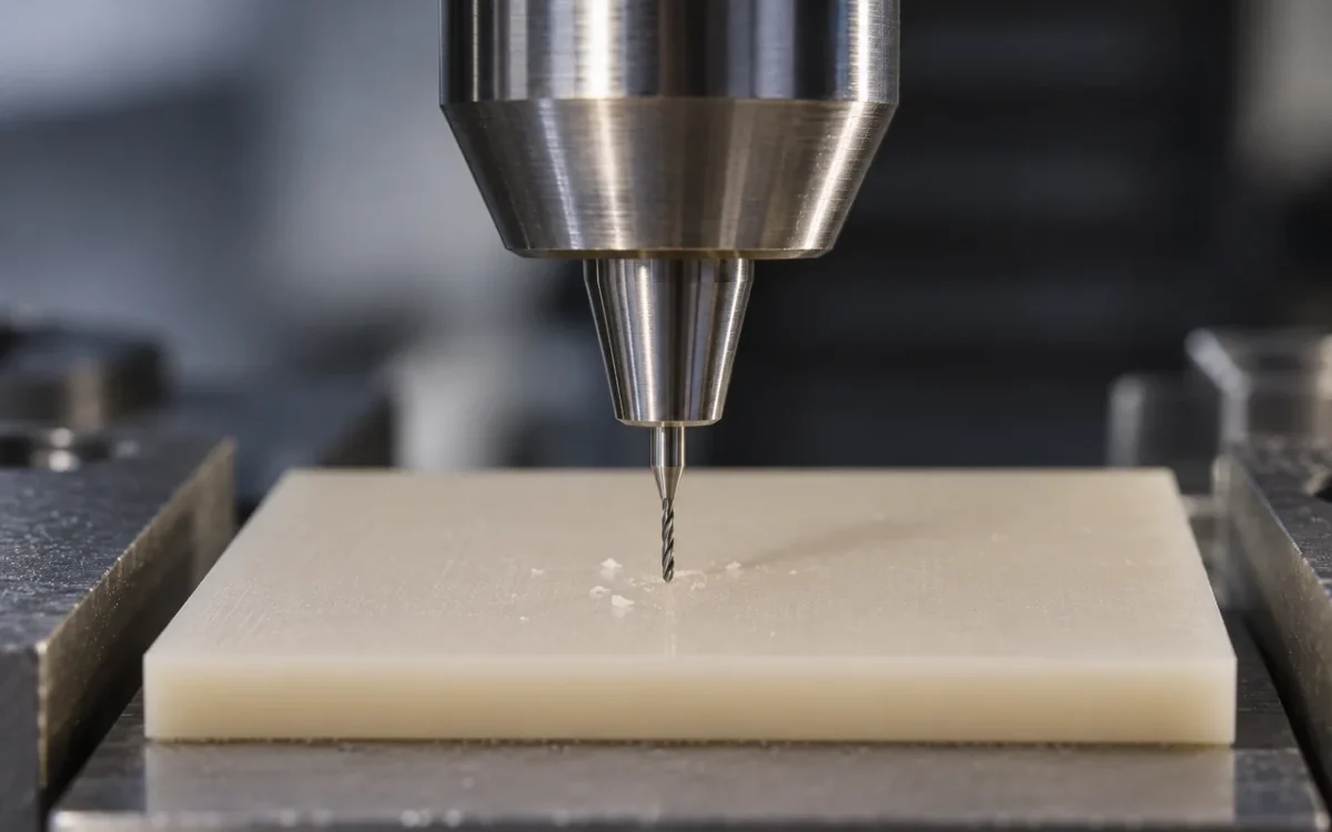
초미세홀 가공: 플라스틱·알루미늄 0.2mm 홀과 0.02mm급 가공의 기술 조건
GPN TECHNICAL INSIGHT · 초미세홀 가공
초미세홀 가공: 플라스틱·알루미늄 0.2mm 홀과 0.02mm급 가공의 기술 조건
초미세홀 가공의 성패는 공구 직경 하나로 결정되지 않습니다. 재질과 홀 깊이, 공구의 회전 상태, 칩 배출, 입구·출구 품질을 연결해 검토해야 도면의 작은 원을 반복 생산 가능한 기능으로 구현할 수 있습니다.
플라스틱과 알루미늄의 0.2mm 홀은 적합한 미세드릴과 가공 조건을 갖춘 CNC에서 검토할 수 있는 범위입니다. 그러나 같은 0.2mm라도 얇은 판의 관통홀과 두꺼운 부품의 깊은 홀은 공정 난도가 다릅니다. 직경이 0.02mm, 즉 20μm 수준으로 작아지면 공구 장착·재료 상태·측정 방법까지 더욱 엄격하게 관리해야 합니다.
기계식 미세드릴 가공은 회전하는 절삭날이 소재를 제거해 홀을 형성하는 공정입니다. 적용 가능성을 판단할 때에는 공구가 존재하는 최소 직경, 특정 조건에서 홀을 형성한 결과, 요구 공차를 지속적으로 만족하는 생산 능력을 구분해야 합니다.
이 원칙을 네뷸라이저의 원형 뚜껑에 적용하면, 홀 직경에 더해 조립 기준에 대한 위치와 관통부의 지지 상태가 중요해집니다. 외주를 고정하는 방식, 오목한 면 아래의 지지, 출구 처리와 세정까지 연결해야 부품 단위의 품질을 평가할 수 있습니다.
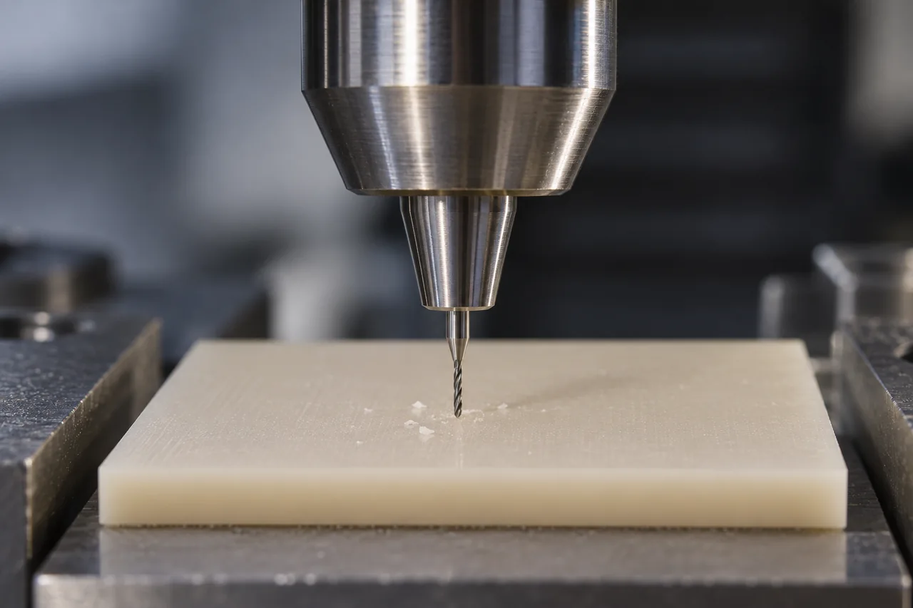
1. 초미세홀 가공: 직경과 깊이의 판단 기준
상용 공구에는 0.03~0.05mm급 미세드릴이 있으며, 일부 제조사는 0.02mm 규격을 포함하는 초미세드릴 제품군도 공급합니다. 따라서 미세한 구멍이라는 이유만으로 CNC 적용을 배제할 필요는 없습니다. 다만 공구의 재질별 적용 범위, 유효 가공 깊이, 장착 조건을 확인해야 실제 부품에 사용할 수 있습니다.
가장 먼저 확인할 값은 홀 깊이 L을 직경 D로 나눈 L/D입니다. 같은 깊이라도 직경이 작아지면 절삭날에서 입구까지 칩이 빠져나오는 상대적인 거리가 길어집니다. 공구의 굽힘과 비틀림에 대한 여유도 함께 검토해야 합니다.
| 홀 직경 D | 가공 깊이 L | L/D | 설계 검토의 의미 |
|---|---|---|---|
| 0.20mm | 0.20mm | 1 | 짧은 관통 구간에서도 입구 위치와 출구 버를 관리합니다. |
| 0.20mm | 1.00mm | 5 | 칩 배출 경로와 공구의 허용 가공 깊이를 확인합니다. |
| 0.20mm | 2.00mm | 10 | 깊은 홀에 적합한 공구와 가공 사이클을 별도로 검토합니다. |
| 0.02mm | 0.20mm | 10 | 두께 0.20mm도 직경 20μm에서는 상대적으로 깊은 홀입니다. |
위 수치는 깊이비를 설명하는 기하학적 예시입니다. 특정 L/D 이하이면 항상 가공된다는 허용 기준은 아닙니다. 공구 목록의 날장과 실제 권장 가공 깊이도 동일한 의미로 취급하지 않습니다.
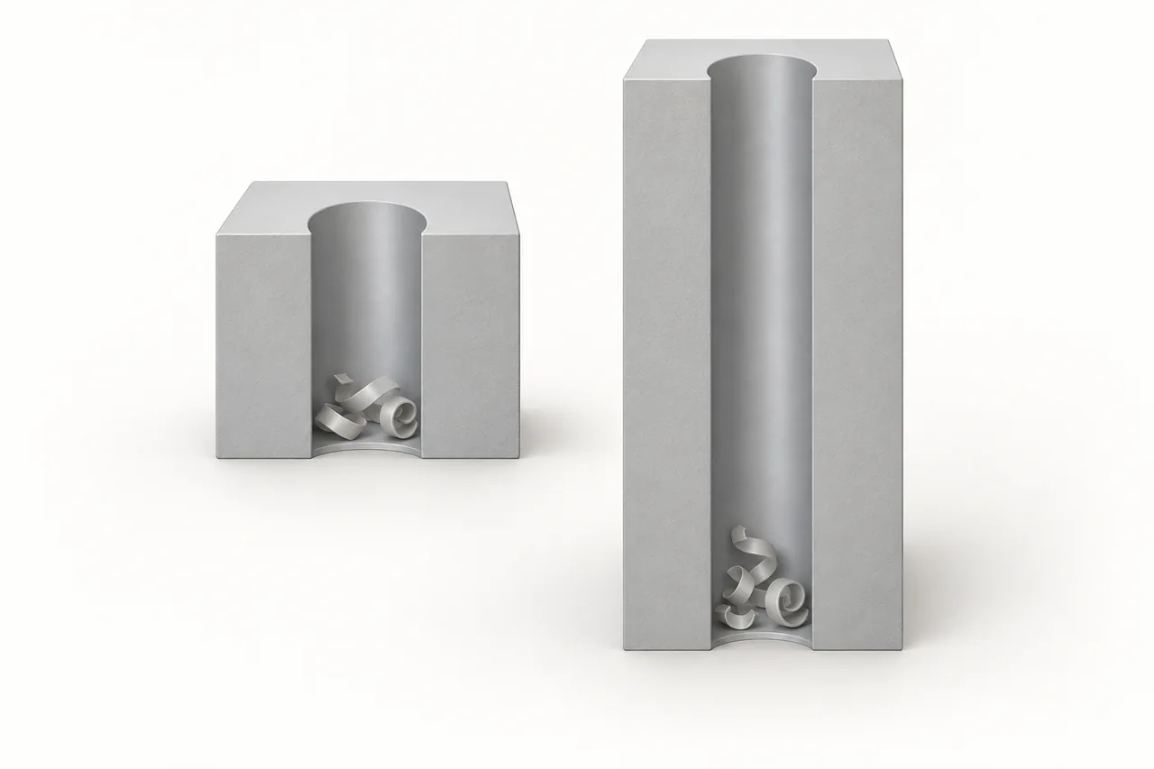
관통홀과 막힌 홀의 도면 정의
관통홀은 드릴 끝이 먼저 빠져나온 뒤 원통부가 완전히 관통할 때까지 이동해야 합니다. 반면 막힌 홀은 원통부 깊이와 드릴 선단이 만드는 바닥 깊이를 구분해야 합니다. 조립·유량에 필요한 길이를 기준으로 깊이를 정의하고, 뒤쪽 형상과 지그의 간섭까지 포함해 접근·관통 여유를 설정합니다.
드릴 선단 길이를 포함한 관통 거리
h = D ÷ [2 × tan(θ ÷ 2)]
대칭 원뿔 선단을 가정하면 h는 선단 높이, D는 드릴 직경, θ는 선단각입니다. 평면에 수직으로 진입하고 드릴 끝의 최초 접촉을 시작점으로 잡을 때, 원통부의 완전 관통에는 국부 두께 t에 h와 관통 여유를 더한 이동을 검토합니다.
실제 이동량은 공구의 선단 형상과 길이 보정 기준, 부품의 두께 편차, 뒤쪽 지그 공간에 맞춰 설정합니다. 부품 전체 높이를 홀 부위의 절삭 두께로 사용하거나, 드릴 끝이 출구에 도달한 위치에서 가공을 종료하면 요구한 유효 홀을 확보하지 못할 수 있습니다.
2. 플라스틱과 알루미늄의 소재별 가공 조건
플라스틱: 열, 복원 변형, 강화재의 영향
플라스틱은 정확한 수지 등급과 충전재 유무를 먼저 확인합니다. POM·PEEK·PMMA·PC를 하나의 절삭 조건으로 묶을 수 없습니다. 열이 축적되면 절삭면의 번짐과 치수 변화가 나타날 수 있으며, 강한 고정력은 가공 후 복원 변형의 원인이 됩니다. 날끝의 상태, 칩 배출, 지지 면적을 함께 관리해야 합니다.
냉각·세정 매체도 소재와의 적합성을 확인합니다. 유리섬유나 탄소섬유가 포함된 수지는 공구 마모와 절단면 손상을 별도로 평가해야 합니다. 특히 섬유 강화 복합재는 비강화 수지의 가공 결과를 그대로 적용하지 않고, 입구·출구의 섬유 돌출과 층간 손상을 추가로 확인합니다.
알루미늄: 합금과 열처리 상태, 날끝 부착의 영향
알루미늄은 합금 번호와 조질, 압연·압출·주조 여부를 구분합니다. 연성이 큰 소재에서는 날끝에 재료가 달라붙거나 칩이 길게 이어지는 현상이 문제가 될 수 있습니다. 주조재는 합금 성분과 내부 조직의 영향도 확인해야 합니다. 작은 드릴에서는 부착물이나 막힌 칩이 차지하는 상대적인 비중이 커집니다.
따라서 “연한 재질이므로 쉽게 가공된다”는 판단만으로 조건을 정하지 않습니다. 날끝 형상과 배출 공간, 냉각·윤활 방법을 해당 합금에 맞추고, 시험품의 홀 치수와 버, 공구 상태를 함께 평가합니다. 소재 선정의 기본 구분은 정밀 부품 소재 선정 기술자료에서도 확인할 수 있습니다.
3. 초미세드릴의 형상과 공구 장착 조건
미세드릴은 외경만 축소한 공구로 이해하기 어렵습니다. 절삭날의 예리함, 중심부의 두께, 칩이 통과하는 홈, 선단 형상이 절삭 저항과 강성에 함께 영향을 줍니다. 홈을 넓히면 배출에 유리할 수 있지만 공구의 단면이 줄어들므로, 배출성과 파손 저항을 동시에 고려해야 합니다.
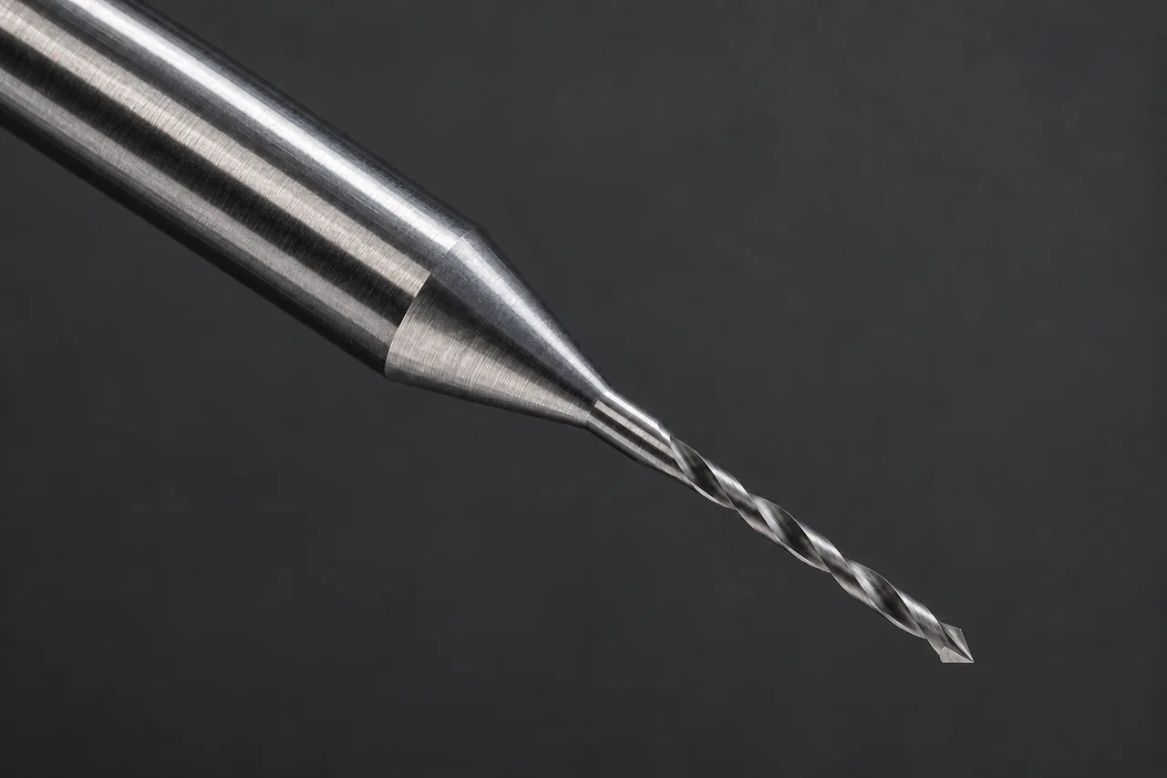
공구 선정 시에는 최소 직경보다 먼저 해당 직경의 재질 적용표와 권장 깊이를 확인합니다. 코팅도 이름만으로 우열을 정하지 않습니다. 공구 형상·코팅·피삭재를 묶어 검증한 조건이 필요합니다. PMMA 미세드릴 가공 연구에서도 회전수와 이송뿐 아니라 코팅과 가공 깊이를 변수로 두고 공구 마모와 표면 거칠기를 함께 평가합니다.
실제 회전 조건에서 확인하는 흔들림
기계의 위치결정 정밀도와 공구 끝의 회전 흔들림은 서로 다른 항목입니다. 콜릿·홀더의 오염, 장착 편차, 돌출 길이, 회전수에 따른 진동은 날끝의 실제 운동에 영향을 줍니다. 장비 사양서의 숫자만으로 가공 상태를 판단하지 않고, 사용 회전수와 장착 상태에서 확인 가능한 측정 방법을 정해야 합니다.
상대 크기 비교 예시
직경 200μm에 대한 흔들림 지표 2μm의 비율: 2 ÷ 200 = 1%
직경 20μm에 대한 동일 지표의 비율: 2 ÷ 20 = 10%
이는 동일한 흔들림이 작은 공구에서 상대적으로 커진다는 설명입니다. 허용 흔들림 기준이나 홀 확대량을 예측하는 식은 아닙니다.
실제 홀 크기는 진입면, 선단 형상, 공구의 탄성 거동과 자기 중심 작용에도 영향을 받습니다. 따라서 측정한 흔들림을 그대로 홀 직경 오차로 환산하지 않습니다. 경사진 면이나 불안정한 표면에 진입하는 경우에는 평탄한 진입부와 지지 방법을 먼저 검토하고, 센터링·파일럿 가공은 해당 미세드릴 제조사의 지침에 맞춰 적용합니다.
4. 초미세홀 가공 조건: 회전수·이송·칩 배출
초미세홀 가공에서는 회전수만 높이는 방식으로 절삭 조건을 결정하지 않습니다. 동일한 회전수라도 직경이 작아지면 날끝 바깥둘레의 절삭속도는 낮아집니다. 반대로 이송을 과도하게 줄이면 안정적인 칩 형성 대신 마찰과 눌림의 비중이 커질 수 있습니다.
vc = π × D × n ÷ 1,000
vf = n × fn
D: 공구 직경(mm) · n: 회전수(min⁻¹)
vc: 절삭속도(m/min) · fn: 회전당 이송(mm/rev) · vf: 분당 이송(mm/min)
예를 들어 회전수를 30,000min⁻¹로 같게 놓으면 직경 0.20mm의 절삭속도는 약 18.85m/min, 0.05mm는 약 4.71m/min, 0.02mm는 약 1.88m/min입니다. 이는 직경과 절삭속도의 관계를 보여주는 계산이며, 해당 회전수를 권장하는 가공 조건표는 아닙니다.
깊이에 맞춘 칩 배출과 재진입
공구는 절삭과 동시에 만들어진 칩을 좁은 홈으로 배출해야 합니다. 깊이가 증가할수록 칩이 빠져나오는 경로가 길어지고 냉각 매체가 날끝까지 도달하기도 어려워집니다. 한 번에 진입하는 깊이, 후퇴 거리, 재진입 속도는 소재·공구·홀 깊이를 묶어 결정합니다.
단속적으로 진입과 후퇴를 반복하는 펙 가공이 필요한 조건도 있지만, 횟수가 많을수록 항상 유리한 것은 아닙니다. 재진입 때 남은 칩을 다시 누르거나 불안정하게 절삭날이 접촉하지 않는지 확인해야 합니다. 다른 재질이나 다른 직경에 사용한 고정 스텝 값을 그대로 옮기지 않습니다.
냉각·윤활은 열 억제와 부착 방지, 칩 배출을 함께 고려합니다. 플라스틱에는 화학적 적합성을 확인한 매체를 사용하고, 공급 위치가 실제 절삭부에 유효한지 점검합니다. 가공 중 장시간 정지 상태로 회전 접촉을 유지하는 조건도 열과 표면 손상 관점에서 검토해야 합니다.
5. 네뷸라이저 뚜껑의 관통 가공: 기준면과 지그 설계
원형 외주와 오목한 중앙부를 가진 뚜껑은 외관상 중심이 분명해 보여도, 그 중심이 조립 기능의 기준과 일치하는지 먼저 확인해야 합니다. 외주 그립 요철은 손으로 잡기 위한 형상일 수 있으므로, 별도 검토 없이 홀 위치를 결정하는 정밀 기준으로 사용하지 않습니다.
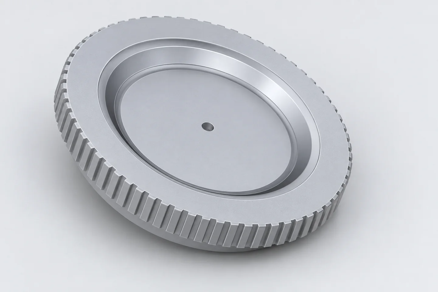
홀의 기능에서 위치 기준을 정하는 순서
관통홀이 통기·유체 통과·조립 중 어떤 역할을 하는지에 따라 필요한 치수와 검사가 달라집니다. 도면에는 홀 직경과 국부 두께, 위치 기준을 표시하고, 맞닿는 면·밀폐면·내부 부품과의 간격을 함께 지정합니다. 겉모양만으로 실제 재질이나 유로를 확정할 수 없으므로 가공 조건은 승인 도면과 소재 정보에 맞춰 설정합니다.
| 기준으로 검토할 형상 | 검토 목적 | 도면·검사에서 연결할 사항 |
|---|---|---|
| 조립 시 맞닿는 면 | 축 방향 위치와 기울기 결정 | 밀폐·안착 기능, 면 손상 허용 범위와 고정 해제 후 상태 |
| 기능상 중심을 정하는 원통면 | 홀의 중심 위치 결정 | 조립 상대 부품의 기준과 가공·측정 좌표의 관계 |
| 방향을 정하는 별도 형상 | 각도 또는 비대칭 홀 위치 결정 | 방향 구속의 필요성, 회전 방지와 공구 접근 공간 |
모든 원형 뚜껑에 동일한 기준 체계를 적용하는 것은 아닙니다. 실제 기능면을 선정한 뒤 가공 지그와 검사 지그가 같은 기준을 재현하도록 설계합니다. 특히 기준면과 홀 사이의 위치 관계는 고정된 부품뿐 아니라 고정을 푼 완성품에서도 확인해야 합니다.
위치 결정·지지·클램핑의 역할 분리
위치 결정 요소는 부품의 좌표를 정하고, 지지 요소는 절삭 하중에 의한 처짐을 억제하며, 클램프는 그 접촉 상태를 유지합니다. 외주를 강하게 누르는 것만으로 중앙의 얇은 바닥을 지지할 수는 없습니다. 반대로 중앙 받침이 높으면 부품이 기준면에서 들뜨거나 고정 중 변형될 수 있어, 받침 높이와 접촉 범위를 함께 관리해야 합니다.
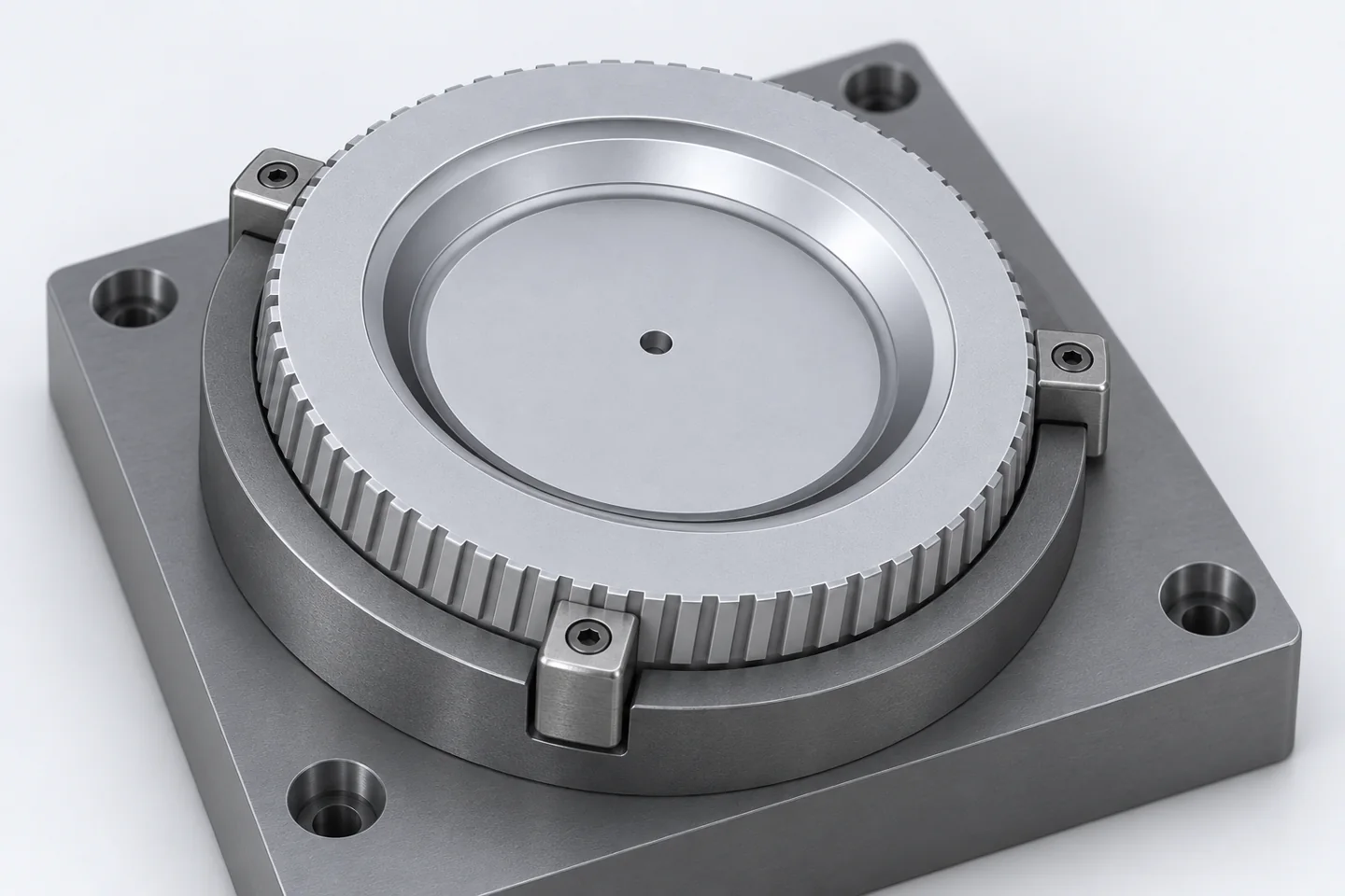
가공부 근처의 지지는 공구가 통과할 공간과 함께 설계합니다. 교체형 받침을 함께 절삭하면 출구 부근을 지지할 수 있지만 받침 칩과 마모를 관리해야 합니다. 여유 구멍을 두는 방식은 공구 간섭을 피하기 쉽지만 구멍 주변의 지지 폭을 확인해야 합니다. 어느 방식을 택하든 공구 선단의 추가 이동, 칩이 머무는 공간, 반복 장착 시의 이물 끼임을 검토합니다.
공구가 진입하는 국부 면의 기울기도 중요합니다. 경사·곡면 접촉은 절삭날에 비대칭 하중을 만들 수 있으므로 실제 진입면과 선택 공구의 지침을 확인합니다. 필요에 따라 평탄한 진입부를 검토하되, 밀폐면이나 조립면을 변경하는 가공은 도면에서 허용된 범위로 제한합니다.
뚜껑 관통홀과 분무 메쉬의 구분
네뷸라이저 뚜껑의 관통홀을 진동 메쉬의 분무 개구부와 동일하게 취급해서는 안 됩니다. 분무 방식과 내부 구조에 따라 각 부품의 역할이 달라집니다. 뚜껑 홀의 직경만으로 분무 입자 크기나 분무량을 산정하지 않고, 지정된 부품 기능과 완성 시스템의 성능을 구분해 평가합니다.
6. 입구·출구 품질과 실제 유효 홀의 검사
작은 버가 기능에 미치는 상대적 영향
미세홀의 출구에서는 남은 얇은 재료가 절단되기 전에 밀리거나 변형될 수 있습니다. 이때 생긴 버와 플라스틱의 잔류 막은 홀을 관통시켰더라도 유효 개구를 줄일 수 있습니다. 설계 단계에서 출구 버의 허용 범위와 세정 상태를 명시해야 하는 이유입니다.
후면 받침과 밀착 지지, 관통 시점의 이송 조건은 출구 상태를 개선하기 위해 검토할 항목입니다. 받침 재료의 칩이나 이물질이 제품에 남지 않는지도 확인합니다. 가공 후 큰 공구로 일괄 면취하거나 수작업으로 다듬으면 미세홀의 입구 형상과 기능 길이가 바뀔 수 있으므로, 후처리까지 하나의 공정으로 검증합니다.
모서리 처리와 세정 후의 최종 상태
모서리 처리는 버를 제거하면서 지정된 홀 직경과 유효 원통 길이, 주변 기능면을 유지하는 범위로 정합니다. 크게 면취해 출구 결함을 가리는 방식은 조립·밀폐·통과 조건을 바꿀 수 있습니다. 얇은 잔류 막과 떨어질 수 있는 칩까지 확인하고, 세정 후에는 액체가 오목한 면이나 작은 홀에 남지 않도록 건조 상태를 평가합니다.
세정액과 공기 공급은 소재 적합성과 요구 청정도에 맞춰 검토합니다. 압축 공기를 사용할 경우 공급 공기의 오염과 불어내는 방향을 함께 확인해야 합니다. 유체 접촉 여부와 부품 기능에 따라 잔류물의 관리 범위를 정하며, 제조 중 세정을 의료기기의 멸균이나 완성품 검증과 동일하게 취급하지 않습니다.
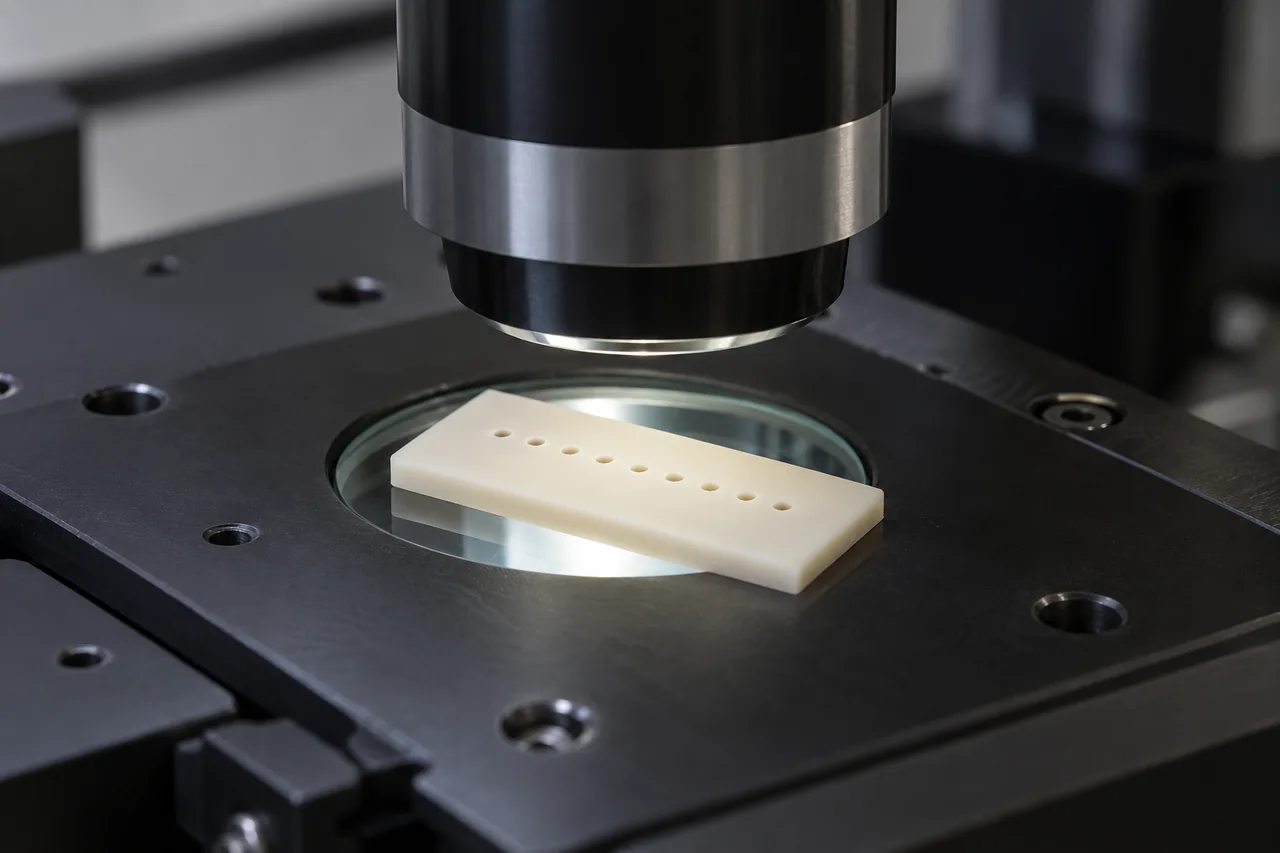
광학 검사에서 확인되는 범위와 한계
작은 홀은 확대 배율만 높여서 검사할 수 없습니다. 교정된 측정계, 조명 방향, 초점, 경계 검출 조건이 함께 필요합니다. 입구와 출구의 윤곽을 측정한 결과만으로 내부 전체가 동일한 원통이라고 판단해서도 안 됩니다.
| 검사 항목 | 확인 내용 | 검사 설계 시 주의점 |
|---|---|---|
| 직경·진원도 | 입구와 출구의 크기, 원형 윤곽 | 버·오염·조명에 의한 경계 변화를 구분합니다. |
| 위치·간격 | 기준면과 기준 좌표에 대한 홀의 위치 | 제품의 실제 기능 기준과 측정 고정을 일치시킵니다. |
| 내부 형상 | 테이퍼, 중간 협착, 벽면 상태 | 필요하면 단면 분석이나 해상도가 검증된 내부 측정을 계획합니다. |
| 출구·청정도 | 버, 잔류 막, 칩과 이물 | 세정 전후와 후처리 후의 상태를 구분합니다. |
| 기능 | 관통성, 요구 유량 또는 조립 조건 | 기능 시험과 치수 검사는 각각의 목적에 맞게 병행합니다. |
측정기의 표시 분해능은 측정 정확도와 같지 않습니다. 20μm급 홀에 X선 CT 등 내부 측정법을 적용할 때에도 장비 이름만으로 판정 가능성을 정하지 않고, 해당 소재·두께·측정 조건에서 유효 해상도와 불확도를 확인해야 합니다. 관통 여부나 유량 시험 역시 직경·진원도 검사를 자동으로 대체하지 않습니다.
치수 검사와 조립·기능 검사의 연결
투과 조명은 개구의 윤곽을, 반사 조명은 표면과 모서리 상태를 확인하는 데 활용할 수 있습니다. 각각의 경계 검출 조건을 정하고 같은 조건으로 비교합니다. 빛이 통과하거나 핀이 들어간다는 결과만으로 위치·진원도·내부 형상까지 합격이라고 판단하지 않습니다.
뚜껑의 조립 검사는 지정된 상대 부품과 결합한 상태에서 안착·간섭·밀폐 조건을 확인합니다. 유량 또는 누설 시험이 필요하면 의도된 통과 경로와 누설을 검사할 경로를 나누고, 막아야 할 구간과 압력 등 시험 조건을 먼저 정합니다. 정상적인 관통 경로를 누설 불량으로 판정하지 않도록 시험 구성을 명확히 해야 합니다.
네뷸라이징 시스템의 안전·성능 시험을 다루는 ISO 27427의 적용 검토는 완성 시스템의 목적과 구성에 맞춰 별도로 진행합니다. 부품 홀의 치수 합격은 완성 기기의 분무 성능을 입증하는 결과와 구분해 관리합니다.
7. 시험 가공에서 반복 생산 조건으로 전환하는 절차
한 개의 홀이 형성된 결과와 일정 수량의 부품이 공차를 만족하는 결과는 구분해야 합니다. 초미세홀 가공은 소재, 공구, 장착, 절삭, 검사 조건을 함께 기록해야 재현성을 판단할 수 있습니다.
- 기능 기준 확정
재질 등급, 홀 직경과 공차, 깊이, 관통 여부, 위치 기준, 허용 버와 청정도를 정의합니다. 유량이 중요하면 치수와 함께 기능 시험 조건도 정합니다.
- 실제 소재와 형상으로 시험
양산과 동일한 소재 상태와 가공 두께를 사용합니다. 평판 시험편의 결과를 곡면·경사면·얇은 벽을 가진 제품에 그대로 적용하지 않습니다.
- 공구 사용에 따른 변화 확인
초기 홀과 사용 진행 후의 홀을 비교하고 직경, 출구 상태, 공구의 마모·파손을 기록합니다. 단일 양품 결과를 근거로 공구 교체 주기를 정하지 않습니다.
- 고정 해제·세정 후 재평가
제품이 열적으로 안정되고 정상 사용 상태로 돌아온 뒤 기능 치수를 확인합니다. 고정한 상태의 측정값과 완성품 측정값을 혼동하지 않습니다.
- 반복성 확인과 조건 관리
공구 재장착과 부품의 반복 탈착, 소재 로트, 설비 상태 변화가 결과에 미치는 영향을 확인합니다. 뚜껑의 기준 접촉부와 받침에 칩이 끼어 위치나 높이가 바뀌지 않는지도 점검합니다. 검사 방법이 유효한 상태에서 측정 분포를 보고 관리 범위와 교체 기준을 정합니다.
초미세홀 가공 검토에 필요한 도면 정보
재질명과 등급·충전재, 가공 부위 두께, 홀 직경·개수·간격, 관통 또는 막힌 홀 여부, 직경·위치 공차, 입구·출구 형상, 조립 상대 부품과 변경 금지면, 허용 버·이물, 요구 수량을 함께 전달하면 검토 범위를 구체화할 수 있습니다.
GPN은 플라스틱·알루미늄의 미세홀에 대해 제품 형상과 기능 조건을 기준으로 가공 적용성을 검토합니다. 0.2mm 홀부터 0.02mm급 초미세홀까지, 목표 직경과 함께 실제 깊이·공차·검사 가능 범위를 확인하는 것이 출발점입니다. 관련 설비·가공 분야는 CNC·MCT 정밀가공에서 확인할 수 있습니다.
ENGLISH · TECHNICAL ARTICLE
Micro-hole machining in plastics and aluminum: technical conditions from 0.2mm to the 0.02mm range
Micro-hole machining depends on the complete relationship between material, hole depth, tool rotation, chip removal and inspection. A 0.2mm hole can be considered for CNC drilling with a suitable micro drill and process. However, a short through-hole and a deep hole of the same diameter present different demands. At 0.02mm, or 20μm, tool mounting, material condition and measurement require particularly careful control.
Mechanical micro-drilling forms holes by removing material with rotating cutting edges. The smallest commercially available tool, a successfully formed individual hole and a repeatable production process meeting tolerances are three different levels of evidence.
Applying these principles to a round nebulizer cap also requires control of functional datums, local support and the condition after breakthrough. The rim, recessed floor and mating features must be considered together with hole geometry.
1. Diameter, depth and the definition of the hole
Commercial micro drills include diameters of 0.03–0.05mm, and some specialist ranges also contain 0.02mm tools. Availability alone does not establish suitability for a particular part. The material application, usable drilling depth and mounting requirements must be checked for the exact tool.
The depth-to-diameter ratio, L/D, is an initial design measure. A 0.20mm hole with depths of 0.20mm, 1.00mm and 2.00mm has ratios of 1, 5 and 10 respectively. A 0.02mm hole through only 0.20mm of material already has an L/D of 10. These are geometric examples, not universal feasibility limits. Flute length should not automatically be treated as the manufacturer’s recommended drilling depth.
Through-hole travel must allow the full cylindrical cutting section to break through after the point emerges. For a blind hole, distinguish the required cylindrical depth from the bottom formed by the drill point. Define depth from the functional requirement and check fixture clearance and features behind the hole.
For an ideal symmetric conical point, its height is h = D/[2tan(θ/2)], where D is drill diameter and θ is the included point angle. Starting with the tip at a flat entry surface and drilling normally through local thickness t, full-diameter breakthrough requires considering t + h plus clearance. Actual point geometry, tool-length reference, thickness variation and fixture space determine the programmed travel. Overall component height is not necessarily the thickness being drilled.
2. Material-specific conditions
Identify the exact polymer grade and reinforcement content. POM, PEEK, PMMA and PC should not share an assumed universal recipe. Heat accumulation can smear the cut surface or change dimensions, while excessive clamping can cause deformation that recovers after release. Tool sharpness, chip removal and workpiece support therefore require joint consideration.
Check the chemical compatibility of cooling and cleaning media. Reinforced polymers require additional evaluation of abrasive wear and edge damage. Fiber protrusion and delamination deserve separate attention; results from an unfilled polymer cannot simply be transferred to a fiber-reinforced composite.
For aluminum, specify alloy, temper and stock condition. Material adhesion to the cutting edge and continuous chips can complicate drilling in ductile grades. Cast material also requires consideration of composition and internal structure. Deposits and trapped chips become relatively significant as tool size decreases. Trial holes should therefore be assessed for dimensions, burrs and tool condition, rather than assuming that a softer material is always easier to drill.
3. Tool geometry, mounting and rotation
A micro drill is more than a conventional tool scaled down. Edge sharpness, web thickness, flute space and point geometry jointly affect cutting resistance and stiffness. Increasing chip space can reduce the supporting tool section. Select the material application and allowable depth for the exact diameter, and evaluate coatings together with tool geometry and workpiece material. Research on PMMA micro-drilling has considered coating, feed, speed and cutting depth while evaluating both tool wear and surface roughness; it does not establish one universal coating for all polymers.
Machine positioning accuracy is distinct from motion at the rotating tool tip. Holder contamination, mounting variation, overhang and speed-dependent vibration can affect the cutting edges. Establish a suitable verification method for the actual mounting and operating speed.
For a relative-scale illustration, a 2μm runout indicator is 1% of a 200μm tool diameter but 10% of a 20μm diameter. This is neither an allowable runout specification nor a prediction of hole enlargement. Entry geometry, point design, elastic behavior and self-centering also influence the result. Check entry-surface preparation and support, and follow the selected micro-drill manufacturer’s instructions on spotting or pilot drilling.
4. Cutting speed, feed and chip evacuation
Spindle speed alone is not a cutting strategy. Peripheral cutting speed follows vc = πDn/1,000, where D is in millimeters, n is in revolutions per minute and vc is in meters per minute. Feed speed is vf = nfn, where fn is feed per revolution and vf is in millimeters per minute.
At an illustrative constant 30,000rpm, diameters of 0.20mm, 0.05mm and 0.02mm correspond to approximately 18.85m/min, 4.71m/min and 1.88m/min. This calculation explains the diameter relationship; it is not a recommended operating-speed table. Excessively low feed can also increase rubbing and deformation rather than produce stable chip formation.
As the hole deepens, chips must travel farther along narrow flutes and coolant access becomes more difficult. Set penetration increments, retraction distance and re-entry speed for the combination of material, tool and depth. Peck drilling may be appropriate, but more frequent pecking is not automatically better. Check whether remaining chips are compressed during re-entry or whether contact becomes unstable. Do not transfer a fixed peck increment from another diameter or material without validation.
Cooling and lubrication address heat, adhesion and evacuation together. Confirm compatibility with the polymer and effective delivery to the cutting zone. Prolonged rotating contact without useful axial cutting also needs evaluation for heat and surface damage.
5. Nebulizer cap through-holes: datums, support and fixture design
A round cap with a recessed center may have an obvious visual center, yet its functional center must be established from assembly requirements. A grooved gripping rim is not automatically a precision locating surface. Define whether the hole serves ventilation, fluid passage or assembly, and specify its diameter, local thickness and location along with protected mating or sealing faces. Geometry alone does not establish the actual material or flow path.
A mating face may establish axial seating and inclination; a functional cylindrical surface may establish the center. Add an orientation feature where an angular or asymmetric relationship requires it. Select the datum system for the actual function, then reproduce it in both machining and inspection. Assess the finished part after release as well as the clamped condition.
Locating, supporting and clamping the cap
Locators establish position, supports resist deflection and clamps maintain contact. Strong rim clamping does not by itself support a thin central floor. An excessively high central support can instead lift the part from its datum or deform it during clamping. Control support height and contact area together.
Support near the hole must also provide breakthrough clearance. A replaceable backing insert can support the exit region, but its chips, wear and contamination need control. An open clearance hole reduces direct tool interference but leaves a support span that must be evaluated. Check additional point travel, chip accumulation and debris at locating contacts during repeated loading.
Check the local entry angle against the selected tool’s instructions. Inclined or curved contact can load the cutting edges unevenly. Any proposed flat entry preparation must remain within approved limits for mating and sealing faces.
A cap through-hole should not be treated as an atomizing aperture in a vibrating mesh. Component roles depend on the nebulization method and internal design. Cap-hole diameter alone cannot establish aerosol droplet size or output; assess the specified component function separately from complete-system performance.
6. Entry, exit, cleanliness and the effective opening
At breakthrough, the remaining thin layer can deform before it separates. Exit burrs or residual polymer film may reduce the effective opening even when the drill has passed through. Define acceptable burrs and cleanliness at the design stage.
Backing support, close contact behind the workpiece and breakthrough feed are potential process controls. Check that the backing does not introduce chips or contamination. Large-tool chamfering or manual deburring may change the entry geometry and functional hole length; validate the finishing operation as part of the complete process.
Edge finishing must retain the specified bore diameter, effective cylindrical length and nearby functional surfaces. An enlarged chamfer can change assembly, sealing or passage conditions. Check removable chips and thin residual film, then assess drying in the recessed surface and small passage. Select cleaning media for material compatibility and the required cleanliness. If compressed air is used, control supply contamination and blowing direction. Manufacturing cleaning is distinct from sterilization and finished-device validation.
Dimensional inspection and assembly checks
Inspection requires more than high magnification. A calibrated system, lighting, focus and consistent edge detection are essential. Measure entry and exit diameter and roundness, hole position relative to functional datums, and burrs or contamination. Visible outlines at the two ends do not prove a uniform internal cylinder.
Where internal taper, a restricted throat or wall condition matters, plan section analysis or a validated internal measurement method. For X-ray CT, verify effective resolution and measurement uncertainty for the actual material, thickness and setup; the equipment category alone does not demonstrate that a 20μm hole can be evaluated. Display resolution is not measurement accuracy. Flow or passage testing can complement dimensional inspection but does not automatically replace it.
Transmitted illumination can support opening-outline measurement, while reflected illumination can reveal surface and edge condition. Set the edge-detection conditions for each purpose. Light passage or pin entry alone does not verify location, roundness or the complete internal profile.
Assembly evaluation uses the specified mating components to check seating, interference and sealing. Where flow or leakage tests are required, distinguish intended passages from unintended leakage paths and define blocked sections, pressure and other boundary conditions. A designed through-path should not be classified as a leak by an inappropriate test setup.
ISO 27427 addresses safety and performance testing of nebulizing systems. Its applicability is reviewed against the complete system and intended use. Acceptance of a component’s hole dimensions remains separate from evidence of the finished device’s nebulization performance.
7. From trial machining to a repeatable process
First, define material grade, diameter and tolerance, depth, through or blind configuration, positional datums, permitted burrs and cleanliness. Include functional test conditions where flow or assembly matters.
Second, test the intended material condition and machining thickness. A flat coupon does not automatically represent an inclined entry, curved surface or thin-walled production part. Third, compare early holes with those made later in tool use and document dimensions, exit condition and tool wear or damage. One acceptable hole is insufficient to set a tool replacement interval.
Fourth, reassess the part after unclamping, cleaning and thermal stabilization. Distinguish an in-fixture reading from the finished-part condition. Finally, examine variation caused by tool remounting, repeated part loading, material lots and machine state. For a cap, also check whether chips at datum contacts or supports change its position or height. Establish control ranges and replacement criteria from measurement distributions obtained with a valid inspection method.
For a technical review, provide material grade and fillers, local thickness, hole diameter, quantity and spacing, depth definition, diameter and position tolerances, entry and exit geometry, mating components and protected faces, allowable burrs or contamination, and required production quantity. GPN evaluates micro-hole applications in plastics and aluminum against the actual geometry and functional requirements. From 0.2mm holes to the 0.02mm range, diameter, depth, tolerance and inspection capability must be reviewed together.
추가 정보
주제 요약
플라스틱·알루미늄의 초미세홀 가공을 검토할 때에는 직경뿐 아니라 깊이비, 소재 등급, 공구 형상, 장착·회전 상태, 칩 배출과 측정 방법을 함께 확인합니다. 공구의 최소 직경과 반복 생산 가능한 품질 범위를 구분하고, 네뷸라이저 뚜껑과 같은 형상에서는 기능 기준·지지·고정·관통 여유와 조립 검사를 연결합니다.
핵심 포인트
- 0.2mm는 200μm, 0.02mm는 20μm이며 동일 두께에서 깊이비가 10배 달라집니다.
- 0.03~0.05mm급뿐 아니라 0.02mm 규격을 포함하는 상용 미세드릴 제품군도 있습니다.
- 플라스틱의 수지 등급·강화재와 알루미늄의 합금·조질을 구분합니다.
- 회전수, 회전당 이송, 진입 깊이와 후퇴 조건을 묶어 검증합니다.
- 입구·출구의 윤곽, 내부 협착, 버·이물과 기능은 서로 다른 검사 항목입니다.
- 원형 뚜껑은 외관 중심보다 조립 기능을 기준으로 위치를 결정하고, 중앙부 지지와 공구 관통 공간을 함께 설계합니다.
- 가공 후 고정 해제·세정·열적 안정화 상태에서 완성품을 평가합니다.
- 뚜껑 관통홀과 분무 메쉬 개구부, 부품 치수 검사와 완성 기기 성능 시험을 구분합니다.
자주 묻는 기술 질문
일반 CNC로 0.2mm 홀을 가공할 수 있습니까?
적합한 미세드릴과 장착·회전·이송 조건을 갖춘 CNC에서 검토할 수 있습니다. 장비 분류만으로 가능 여부를 확정하지 않고 재질, 깊이와 공차, 출구 품질을 함께 확인합니다.
0.02mm 드릴이 있으면 같은 직경의 홀도 안정적으로 생산할 수 있습니까?
공구 공급 여부는 첫 조건입니다. 해당 소재와 깊이에서의 절삭 안정성, 공구 수명, 치수 분포와 검사 가능성을 시험으로 확인해야 반복 생산 범위를 정할 수 있습니다.
홀 깊이는 제품 두께와 항상 같습니까?
수직 관통홀의 원통 구간은 부위 두께와 연결되지만, 실제 공구 이동에는 선단 길이와 관통 여유가 포함됩니다. 막힌 홀에서는 원통부 깊이와 선단까지의 총깊이를 구분합니다.
공구 흔들림은 그대로 홀 직경 오차가 됩니까?
직접 환산할 수 없습니다. 선단과 진입면, 공구의 탄성 거동, 자기 중심 작용 등이 함께 영향을 주므로 실제 가공한 홀의 치수와 위치를 측정해야 합니다.
가공 후 확대 사진만으로 품질을 판정할 수 있습니까?
교정과 조명 조건이 없는 확대 사진은 치수 측정을 대신하지 못합니다. 또한 입구 영상만으로 내부 협착이나 출구 상태를 확정할 수 없어 필요한 검사 범위를 먼저 정해야 합니다.
뚜껑 외주를 잡으면 홀의 중심 위치도 결정됩니까?
외주가 조립 기능의 기준인지 확인해야 합니다. 그립 요철이나 외관면을 정밀 기준으로 바로 사용하지 않고, 기능면과 가공·검사 좌표를 연결합니다. 고정 해제 후의 위치와 형상도 확인합니다.
네뷸라이저 뚜껑의 홀 직경으로 분무 입자 크기를 판단할 수 있습니까?
뚜껑 관통홀과 분무를 만드는 메쉬 개구부는 역할이 다를 수 있습니다. 뚜껑의 치수만으로 입자 크기나 분무량을 판단하지 않고, 부품 기능과 완성 시스템의 시험 결과를 구분합니다.
검토 요청 시 가장 먼저 필요한 자료는 무엇입니까?
소재 등급과 충전재 정보, 부위 두께, 홀 직경·깊이·공차, 관통 여부와 입구·출구의 기능 조건이 표시된 도면이 필요합니다. 조립 상대 부품과 변경 금지면, 수량과 세정·검사 요구도 함께 전달합니다.
관련 기술자료
관련 태그

Related posts
시계 스프링바 제조: 튜브·핀·숄더 가공과 스프링 선정, 반복 압축·부식 피로 검사
정밀 부품 도면의 표면 거칠기 지시: Ra·Rz 값과 외관·밀봉·접촉 기능의 관계
명품 무브먼트 마감: 앵글라주·블랙 폴리싱·제네바 스트라이프의 정밀 제조
3축 가공과 5축 가공: 공구 접근·셋업·정밀도와 제조 원가 비교
외장 SSD 케이스: 알루미늄 방열 구조와 정밀가공 설계
