MIM 소결 수축을 고려한 금속 분말 선정과 금형 보정 설계
METAL INJECTION MOLDING
MIM 소결 수축을 고려한 금속 분말 선정과 금형 보정 설계
MIM의 최종 치수는 금형 형상에 원료와 공정의 수축 거동이 더해져 결정됩니다. 금속 분말의 입도·형상, 피드스톡의 체적 충전율, 성형 균일성, 소결 조건을 함께 검토해야 금형 보정값을 반복 생산에 사용할 수 있습니다.
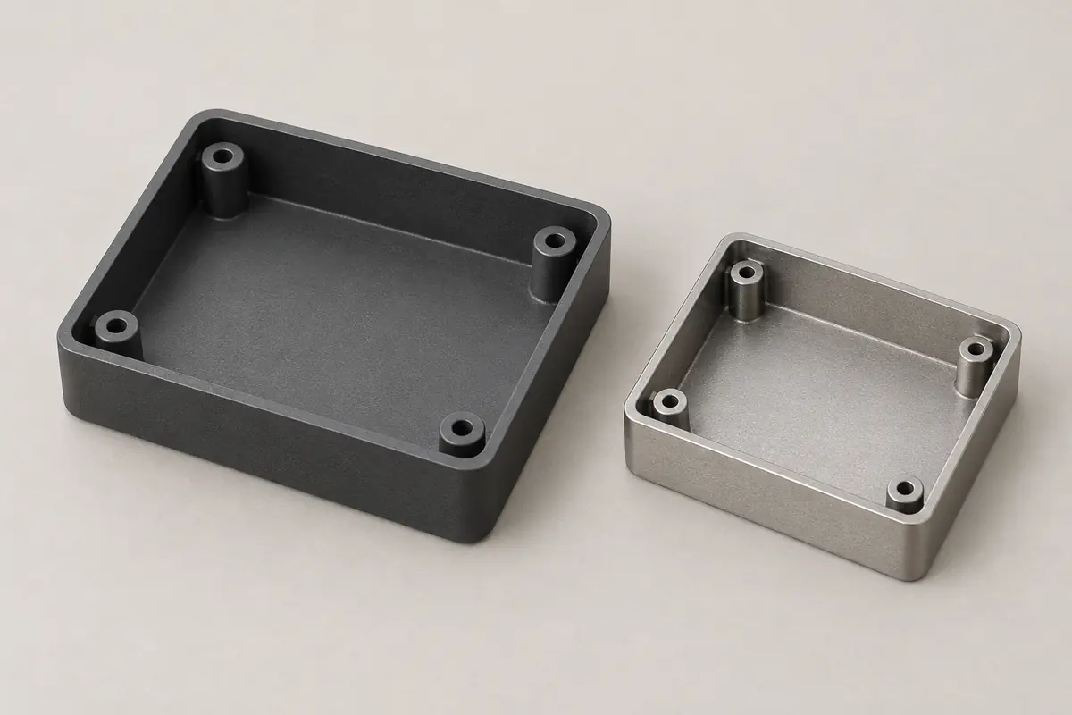
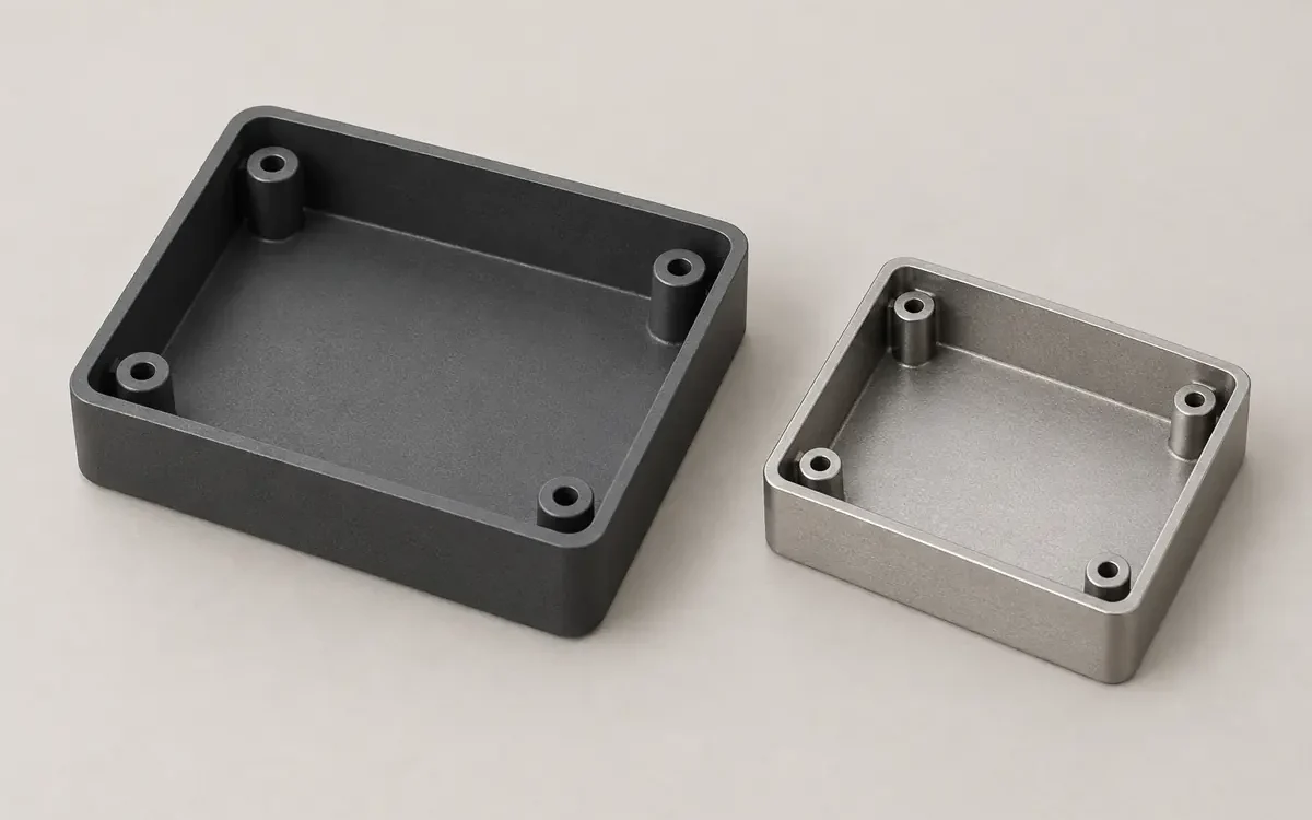
소형 금속 하우징의 외곽 길이가 맞아도 보스 간 거리와 구멍 위치가 어긋나면 조립은 성립하지 않습니다. 반대로 수축량이 크더라도 각 부위의 변화가 안정적으로 재현되면 금형 치수를 보정해 목표 형상을 확보할 수 있습니다. MIM 소결 수축 설계의 목표는 목표 밀도와 형상을 확보하면서 최종 치수의 편차를 관리하는 것입니다.
성형체 기준 선형 수축률, 체적 수축률, 완성품 기준 확대율을 구분합니다.
분말 특성·바인더·사출·탈지·소결 조건을 하나의 조합으로 검증합니다.
외곽뿐 아니라 구멍, 보스 간 거리, 평면도와 조립 상태를 확인합니다.
1. 성형체에서 소결품으로 이어지는 치밀화와 수축
MIM은 금속 분말과 바인더를 혼합한 피드스톡을 금형에 사출해 성형체를 만듭니다. 성형체에는 최종 금속 부품에 남을 분말과 이후 제거할 바인더가 함께 들어 있습니다. 바인더는 분말이 흐르도록 돕고 냉각 후 형상을 유지하는 역할을 합니다.
탈지에서는 바인더를 단계적으로 제거합니다. 이때 분말 골격이 무너지지 않도록 형상을 유지하면서 이후 제거와 가스 배출에 필요한 경로를 확보합니다. 바인더가 빠지는 과정과 부품 전체가 치밀해지는 과정은 구분해야 합니다. 정상적인 탈지에서 주요 외형을 유지한 뒤, 소결에서 입자 사이의 연결과 치밀화가 진행되면서 큰 치수 감소가 발생합니다.
소결 중 수축은 단순한 열팽창의 반대 현상이 아닙니다. 금속 입자 사이의 기공이 줄어드는 치밀화와 연결되어 있습니다. 따라서 비교 치수는 동일한 기준 온도와 측정 상태에서 확보해야 합니다. 뜨거운 부품의 길이를 냉각된 성형체와 비교하면 열팽창까지 수축률에 섞이게 됩니다.
금속 입자가 연결되었다는 사실만으로 목표 밀도가 확보됐다고 판단하지 않습니다. 잔류 기공과 최종 밀도, 필요한 기계적 성질을 별도로 확인해야 합니다. 수축을 작게 만들기 위해 치밀화를 충분히 진행하지 않은 조건은 치수 확보의 해결책이 될 수 없습니다.

2. 선형 수축률과 금형 확대율의 계산
“20~30% 줄어든다”는 설명을 설계에 적용하려면 우선 길이와 부피 중 무엇을 비교했는지, 어느 단계의 치수를 기준으로 했는지 확인해야 합니다. 원료와 공정에 따라 수축 거동이 달라지므로 특정 비율을 모든 MIM 부품의 보정값으로 사용하지 않습니다.
성형체의 길이를 Lg, 냉각 후 소결품의 길이를 Ls라고 하면 선형 수축률 s는 다음과 같습니다. 식에 넣는 s는 백분율이 아닌 소수입니다. 20% 수축은 s = 0.20으로 계산합니다.
s = (Lg − Ls) / Lg
Lg = Ls / (1 − s)
완성품 기준 확대계수 K = 1 / (1 − s)
완성품 기준 확대율 = (K − 1) × 100%
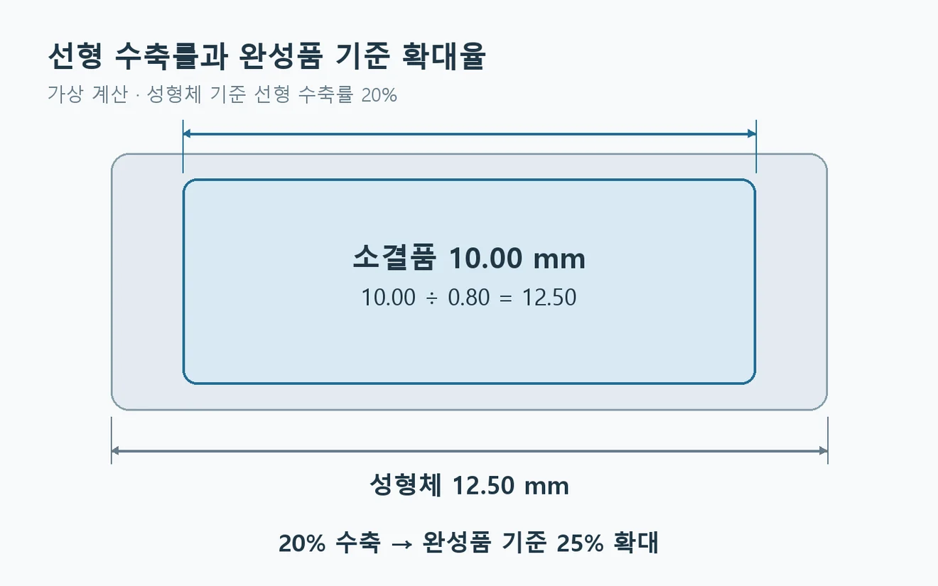
가상 계산: 최종 10mm, 선형 수축률 20%
최종 길이가 10.00mm이고 성형체 기준 선형 수축률이 20%라고 가정하면 필요한 성형체 길이는 10.00 / 0.80 = 12.50mm입니다. 완성품을 기준으로는 25% 확대에 해당합니다. 20%만 크게 만든 12.00mm가 같은 비율로 수축하면 최종 길이는 9.60mm가 됩니다.
| 가정한 선형 수축률 | 확대계수 K | 완성품 기준 확대율 | 최종 10mm에 대응하는 성형체 |
|---|---|---|---|
| 15% | 1.1765 | 17.65% | 11.765mm |
| 18% | 1.2195 | 21.95% | 12.195mm |
| 20% | 1.2500 | 25.00% | 12.500mm |
| 25% | 1.3333 | 33.33% | 13.333mm |
| 30% | 1.4286 | 42.86% | 14.286mm |
표는 분모의 차이를 설명하기 위한 가상 계산입니다. 표시된 수축률이 특정 소재의 권장값이나 GPN 제품의 실측값을 뜻하지는 않습니다. 실제 금형 치수에는 금형에서 성형체로 이어지는 사출 수축, 원료 공급사의 확대계수 정의, 제품별 보정과 후가공 여유까지 반영해야 합니다.
선형 수축과 체적 수축의 구분
세 방향이 동일하게 수축하는 조건에서 체적비는 Vs / Vg = (1 − s)3입니다. 선형 수축률 20%의 가상 예에서는 체적비가 0.83 = 0.512이므로 체적 수축률은 48.8%입니다. 길이 기준 20%와 부피 기준 20%는 서로 다른 상태를 나타냅니다.
공급사의 OSF 또는 확대계수가 금형 캐비티와 완성품의 관계를 이미 포함한다면 사출 수축을 다시 더하지 않아야 합니다. 반면 성형체와 소결품 사이의 실측값만 제공됐다면 캐비티에서 성형체로 이어지는 변화는 별도로 확인해야 합니다.
3. 금속 분말 선정: 입도·형상·청정도의 균형
분말 선정은 먼저 완성품에 필요한 합금 조성, 내식성, 강도, 열처리 상태를 정한 뒤 진행합니다. 같은 합금 이름을 사용하는 분말이라도 입도 분포와 제조 방법, 표면 산화 상태가 다르면 사출과 소결 거동이 달라질 수 있습니다.
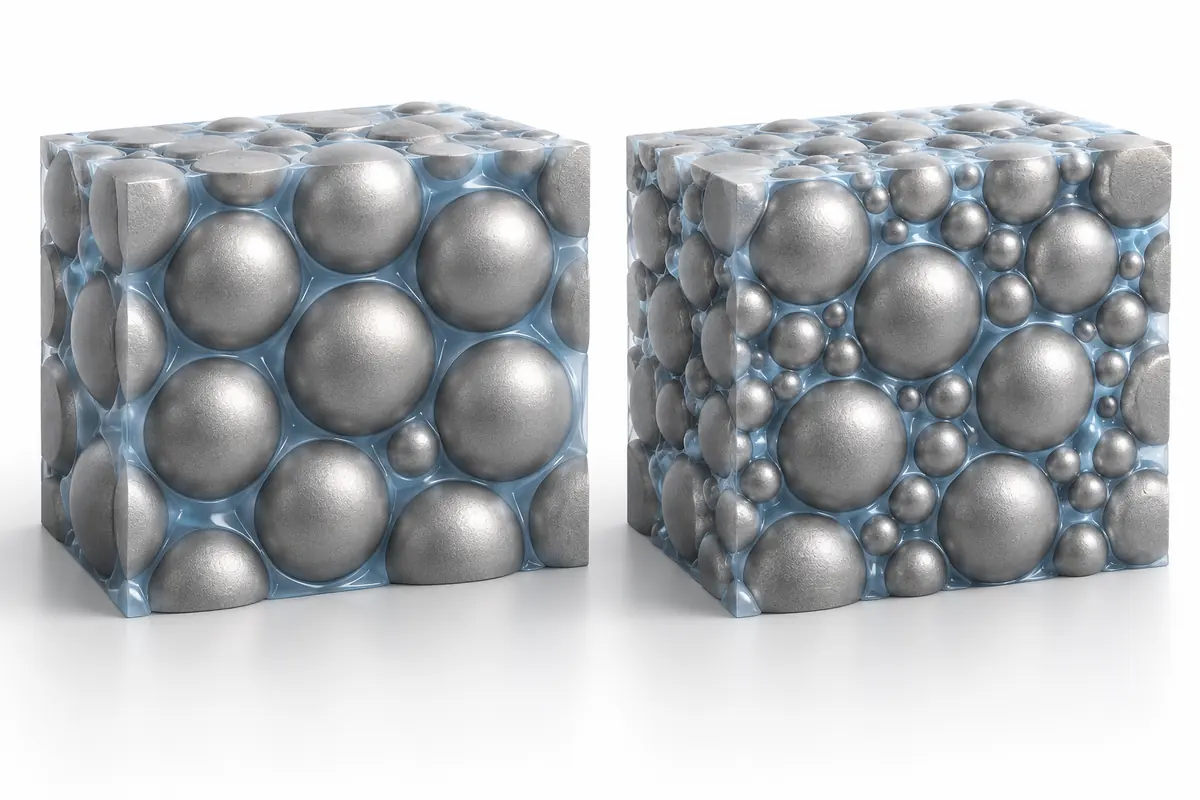
평균 입도와 입도 분포
D50이 같아도 미세 입자와 큰 입자의 비율은 다를 수 있습니다. D10·D50·D90은 분포를 함께 읽기 위한 지표입니다. 비교할 때는 체적 기준인지 개수 기준인지, 측정 방법과 분산 조건이 같은지 확인해야 합니다. 레이저 회절로 얻은 크기는 광학 모델에 기반한 등가 입경이므로 실제 입자의 형상 관찰을 대신하지 않습니다.
미세 분말은 소결 반응과 작은 형상의 재현에 유리한 조건을 만들 수 있습니다. 그러나 비표면적 증가에 따른 바인더 요구, 점도 상승, 응집과 표면 산화의 영향도 커질 수 있습니다. 조대한 입자는 원료 비용과 취급에서 유리할 수 있지만, 미세 형상과 표면 상태, 목표 밀도에 필요한 소결 조건을 함께 검토해야 합니다.
여러 크기의 입자를 혼합하면 작은 입자가 큰 입자 사이의 공간을 채워 충전 상태를 개선할 수 있습니다. 다만 혼합비를 바꾸면 유동과 분리 거동도 달라집니다. 높은 충전밀도가 확보되는 조합인지, 사출 과정에서 균일하게 이동하는 조합인지 두 가지를 함께 시험해야 합니다.
입자 형상과 화학 청정도
구형에 가까운 입자는 흐름과 높은 충전율에 유리할 수 있습니다. 입자 사이의 마찰과 바인더 제거 후 골격 유지도 중요하므로, 구형도 하나만으로 원료를 결정하지 않습니다. 응집체, 위성 입자, 내부 기공과 불규칙 입자를 함께 관찰합니다.
산소·탄소와 수분, 이물의 영향은 합금과 소결 분위기에 따라 달라집니다. 분말 표면의 산화물과 탄소 변화는 치밀화와 최종 조직에 영향을 줄 수 있습니다. 입도와 함께 화학 성분, 보관 조건, 제조 로트의 일관성을 확인해야 원료 변경 후 치수와 물성의 변화를 설명할 수 있습니다.
| 선정 항목 | 검토 목적 | 확인 자료 |
|---|---|---|
| 합금 조성·불순물 | 목표 물성과 소결 반응의 일관성을 확보합니다. | 성분 성적서, 산소·탄소 등 필요한 분석 결과를 확인합니다. |
| 입도 분포 | 형상 재현·패킹·점도·소결성을 함께 판단합니다. | 분포 곡선, D10·D50·D90, 측정 조건을 확인합니다. |
| 형상·응집 | 유동과 골격 유지, 국부 불균일 가능성을 검토합니다. | 현미경 관찰과 응집·위성 입자 상태를 확인합니다. |
| 겉보기·탭 밀도 | 분말의 충전 특성과 로트 변화를 비교합니다. | 동일 시험 방법의 결과를 비교합니다. |
| 피드스톡 적합성 | 선택한 바인더와 사출 조건에서 사용 가능한지 확인합니다. | 충전율, 유변학적 특성, 시험 성형·소결 결과를 확인합니다. |
분말의 겉보기 밀도나 탭 밀도는 분말층의 충전 특성을 나타냅니다. 이 값을 성형체 내부의 금속 체적비 또는 소결품 밀도로 바로 대체하지 않습니다.
4. 피드스톡 체적 충전율과 수축의 관계
피드스톡의 분말 충전율은 분말과 바인더의 전체 부피에서 금속 분말이 차지하는 비율입니다. 금속 분말과 바인더는 밀도가 크게 다르므로 중량비와 체적비를 구분해야 합니다. 동일한 중량비라도 합금이나 바인더 밀도가 달라지면 체적 충전율은 달라집니다.
φ = (mp / ρp) / [(mp / ρp) + (mb / ρb)]
φ: 금속 분말 체적분율, m: 질량, ρ: 밀도
아래첨자 p는 분말, b는 바인더입니다. 여러 바인더 성분은 각 성분의 부피를 합산합니다.
동일한 최종 밀도를 목표로 한다면 초기 금속 체적분율이 높은 성형체는 상대적으로 작은 체적 감소로 목표 밀도에 도달할 수 있습니다. 그러나 분말 충전율을 지나치게 높이면 바인더가 입자 사이를 충분히 채우지 못하거나 점도가 높아져 충전 불량이 발생할 수 있습니다. 반대로 바인더가 과다하면 분리와 탈지 중 형상 유지 문제가 커질 수 있습니다.
임계 충전율은 최종 배합의 목표값과 구분합니다. 선택한 분말·바인더의 혼합 거동과 점도 변화로 사용 가능한 범위를 찾고, 실제 금형에서 충전·보압·탈형이 안정적으로 이루어지는 배합을 검증해야 합니다. 단순히 가장 많은 분말을 넣은 조건을 채택하지 않습니다.
체적 충전율로 수축 경향을 설명하는 단순 모델
금속의 질량과 이론 밀도가 유지되고, 성형체에 추가 공극이 없으며, 세 방향이 동일하게 수축한다고 가정합니다. 성형체의 금속 체적분율을 φ, 소결품의 상대밀도를 R이라 하면 다음의 관계를 얻습니다.
Vs / Vg = φ / R
Ls / Lg ≈ (φ / R)1/3
s ≈ 1 − (φ / R)1/3
가상 조건으로 φ = 0.60, R = 0.98을 넣으면 선형 수축률은 약 15.1%입니다. R을 유지하면서 φ를 0.64로 바꾸면 약 13.2%가 됩니다. 이 계산은 분말 체적비와 수축의 관계를 이해하기 위한 질량보존 모델입니다. 산화물 환원, 조성 변화, 추가 공극, 성형체 밀도 분포와 수축 구속을 포함하지 않으므로 금형 확정값으로 사용하지 않습니다.
원료의 균일성과 사출 중 분리
전체 배합비가 같아도 부품의 일부에 바인더가 상대적으로 많이 모이면 국부 수축이 달라질 수 있습니다. 혼련 균일성, 사출 온도, 유동 경로, 게이트와 보압을 함께 검토해야 합니다. 검은색 성형체의 외관만으로 내부의 분말 분포가 균일하다고 판단하기는 어렵습니다.
피드스톡을 변경할 때는 합금 이름뿐 아니라 원료 등급, 로트, 바인더 시스템과 공급사의 확대계수 적용 조건을 확인합니다. 회수 원료를 혼합하는 경우에는 허용 비율과 열 이력, 오염 관리까지 포함해 재검증해야 합니다.
5. 금형 보정: 전체 확대와 기능부 국부 보정
금형 설계의 출발점은 후가공·열처리·표면처리까지 포함한 완성품 도면입니다. 외곽 치수만 먼저 확대하고 이후 구멍이나 체결면을 조정하면 기준면과 공차 관계가 어긋날 수 있습니다. 완성 치수, 소결 상태 목표 치수, 성형체 목표 치수, 금형 캐비티·코어 치수를 순서대로 연결합니다.
초기 확대계수는 원료 공급사의 검증된 데이터와 적용 조건을 확인해 선정합니다. 이후 같은 원료·사출·탈지·소결 조건으로 제작한 시험품에서 실제 치수 변화를 확인합니다. 캐비티와 성형체 사이의 변화까지 포함한 계수인지 기록해야 보정의 중복을 막을 수 있습니다.
길이·구멍·중심 거리의 독립적인 평가
외곽 길이, 구멍 지름, 보스 높이, 구멍 중심 거리는 각각 기능이 다릅니다. 균일한 자유 수축이 성립하면 공통 계수로 설명할 수 있지만, 실제 부품에서는 코어핀 거동과 국부 밀도, 지지 조건에 따라 차이가 생길 수 있습니다. 조립에 필요한 치수는 개별 측정 특성으로 분리해 평가합니다.
평면도와 위치도는 길이 수축률만으로 관리되지 않습니다. 한 방향에서 측정한 전체 길이가 합격해도 얇은 바닥이 휘거나 홀 위치가 회전하면 조립 품질은 달라집니다. 기준면과 측정 정렬 방법을 도면 단계에서 정해야 합니다.
가상 계산: 수축 편차 0.2%포인트의 영향
성형체 길이 12.50mm가 20.0% 수축하면 최종 길이는 10.000mm입니다. 동일한 성형체가 20.2% 수축하면 9.975mm가 됩니다. 수축률의 차이 0.2%포인트가 최종 치수 0.025mm, 즉 25μm의 차이를 만드는 가상 사례입니다.
이 관계는 고정된 Lg에서 ΔLs = −LgΔs로 표현할 수 있습니다. 금형 확대계수가 정밀해도 수축률이 생산 중 달라지면 완성 치수가 이동합니다. 평균 치수가 일정하게 어긋나는 문제와 생산품 간 산포가 큰 문제는 원인을 구분해 대응해야 합니다.
작은 구멍과 정밀 접촉면에 추가 가공이 필요한 경우에는 소결품의 형상 변동 안에서도 가공 여유가 확보되는지 확인합니다. 후가공으로 맞출 기능면, 금형과 소결에서 확보할 치수, 보정이 가능한 범위를 개발 초기에 나눠야 합니다.
6. 두께 변화·보스·리브의 수축 대응 설계
얇은 벽에 큰 보스가 붙거나 한쪽에 두꺼운 덩어리가 모인 형상은 충전과 냉각, 바인더 제거, 소결의 진행이 균일한 단면과 달라질 수 있습니다. 완성품의 강성을 확보하면서 공정 중 두께 차이가 지나치게 커지지 않도록 검토합니다.
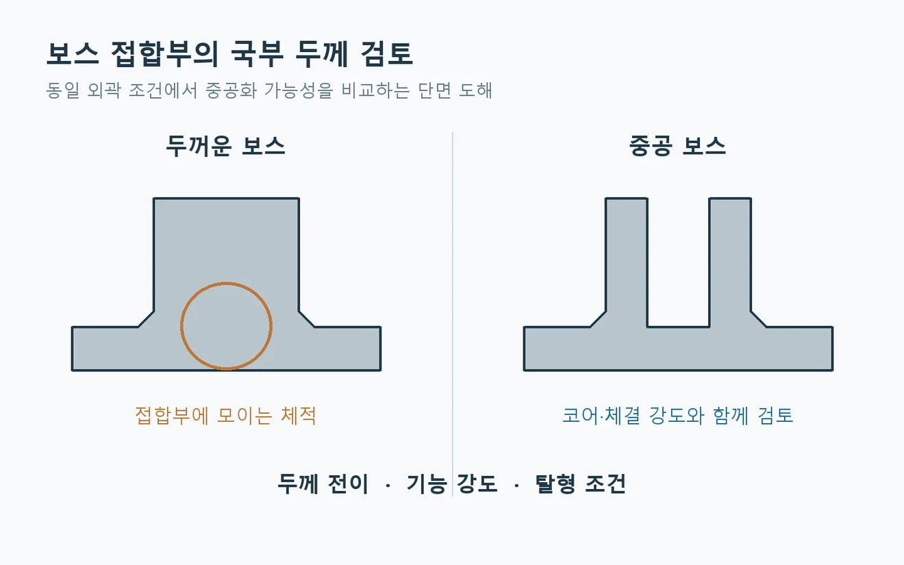
두꺼운 보스의 중공화와 단면 전이
보스 내부를 비우거나 비기능 영역의 체적을 줄이면 국부 두께를 완화할 수 있습니다. 다만 체결 강도, 나사 길이, 코어핀의 지지와 탈형 조건을 동시에 확인해야 합니다. 얇게 만드는 것만으로는 설계가 완성되지 않습니다.
두꺼운 영역과 얇은 영역을 연결할 때는 급격한 단면 변화와 날카로운 내부 모서리를 줄이고 완만한 전이를 검토합니다. 리브는 강성을 높일 수 있지만 접합부에 두꺼운 영역을 만들면 새로운 수축 차이와 변형 원인이 될 수 있습니다. 리브의 위치와 두께는 성형과 소결 결과까지 확인해 결정합니다.
유동 경로와 소결 자세의 동시 검토
게이트 위치는 충전 균일성과 외관 흔적, 분말·바인더 분리 가능성에 연결됩니다. 소결 자세는 자중에 의한 처짐과 지지면 마찰에 연결됩니다. 두 조건은 기능면과 외관면을 중심으로 함께 검토해야 합니다.
제품 형상 때문에 두께 차이가 불가피하면 그 부분을 우선 측정 영역으로 지정합니다. 보스 높이와 중심 거리, 바닥 평면도, 외벽의 기울기처럼 기능에 영향을 주는 변화를 시험품에서 확인합니다. 한 가지 평균 수축률로 모든 형상을 설명하기 어려운 부분을 개발 단계에서 드러내는 작업입니다.
7. 탈지·소결 조건과 수축 구속의 관리
바인더 시스템에 따라 용매·촉매·열적 탈지 등의 경로가 달라집니다. 제거 속도와 형상 유지의 균형이 필요하며, 두꺼운 단면과 막힌 경로에서는 바인더 제거와 가스 배출 조건을 더 주의 깊게 검토합니다. 탈지에서 생긴 균열이나 손상은 소결 후에도 남을 수 있습니다.
소결 온도와 유지시간, 분위기는 치밀화와 합금 조성, 조직에 함께 영향을 줍니다. 온도를 높이면 치밀화가 개선될 수 있는 구간이 있지만, 입자·결정립 성장과 처짐, 조성 변화까지 고려해야 합니다. 모든 합금에 공통으로 적용되는 단일 온도나 시간을 정하지 않습니다.
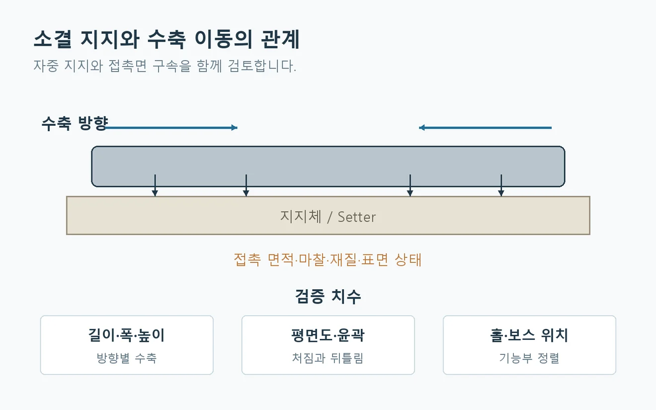
지지체와 자유 수축의 관계
소결품이 지지체 위에서 수축할 때 접촉면 마찰은 자유로운 이동을 구속할 수 있습니다. 부품의 자중과 높은 온도에서의 변형 거동이 함께 작용하므로 지지 위치, 접촉 면적, 지지체 재질과 표면 상태를 검토합니다. 지지 조건이 달라지면 금형을 그대로 사용해도 변형 결과가 달라질 수 있습니다.
돌출 보스나 얇은 면을 지지하려고 접촉을 늘리면 수축 구속이 커질 수 있고, 접촉을 지나치게 줄이면 처짐이 발생할 수 있습니다. 기능면의 형상과 외관 흔적을 확인하면서 지지와 수축 이동의 균형을 찾아야 합니다.
방향별 수축과 로내 배치
길이·폭·높이의 수축이 동일한지 확인합니다. 방향별 차이가 반복되면 원료와 성형의 불균일, 형상과 지지 조건, 열적 조건을 함께 검토합니다. 방향별 확대계수를 적용하기 전에 그 차이가 재현되는 현상인지 확인해야 합니다.
로내 위치와 적재 방식, 지지체 사용 이력은 시험 조건 기록에 포함합니다. 특정 위치에서만 편차가 커지는 문제를 금형 오류로 판단하면 원인을 놓칠 수 있습니다. 로트·캐비티·로내 위치 정보를 함께 추적해야 치수 변화의 경로를 찾을 수 있습니다.
8. 시험 성형과 금형 보정의 검증 절차
- 완성품의 기능 치수와 기준면을 정합니다.
외곽, 체결홀, 중심 거리, 접촉면과 조립 간극을 구분하고 후가공·열처리·표면처리 상태를 지정합니다.
- 원료와 초기 확대계수의 적용 조건을 고정합니다.
분말·피드스톡 등급, 로트, 바인더 시스템, 계수의 분모와 적용 공정 범위를 기록합니다.
- 성형체·탈지체·소결품의 대응 데이터를 확보합니다.
공정 단계별 치수와 질량을 비교합니다. 취약한 탈지체에는 손상을 피하는 측정 방법을 사용합니다.
- 평균 오차와 산포, 형상 변형을 나눠 분석합니다.
캐비티별·방향별·로내 위치별 결과를 비교합니다. 크기 오차와 뒤틀림을 구분합니다.
- 원인이 안정된 뒤 금형을 보정합니다.
공정 조건의 변동을 먼저 줄이고 전체 확대계수 또는 기능부 국부 치수를 수정합니다. 변동이 큰 상태의 평균값에만 맞추지 않습니다.
- 보정 후 조립과 반복 생산을 재검증합니다.
치수 합격 외에 조립력, 기능면 상태와 필요한 물성을 확인합니다. 검증된 원료·금형·공정 조합을 양산 기준으로 관리합니다.
같은 시험품의 공정 전후를 추적할 수 있으면 원인 분리에 유리합니다. 동일 부품을 반복 측정하기 어려운 경우에는 시료의 대응 방식과 표본 조건을 명확히 기록합니다. 측정기 분해능만 확인하지 말고 고정력, 정렬, 온도와 측정 반복성도 확인해야 합니다.
9. 치수 편차의 증상과 원인 분리
| 관찰한 증상 | 검토할 원인 | 우선 확인할 데이터 |
|---|---|---|
| 전체 치수가 일정하게 작거나 큽니다. | 확대계수 정의, 원료 변경, 평균 수축의 이동을 검토합니다. | 캐비티·성형체·소결품의 대응 치수와 원료 이력을 확인합니다. |
| 평균은 맞지만 개체 간 편차가 큽니다. | 피드스톡 균일성, 사출·보압, 로내 배치와 측정 변동을 검토합니다. | 로트·캐비티·위치별 산포와 측정 반복성을 확인합니다. |
| 보스 간 거리나 특정 홀만 어긋납니다. | 코어핀 거동, 국부 두께, 밀도 분포와 국부 구속을 검토합니다. | 성형 단계 위치, 소결 후 위치도, 해당 부위 단면을 확인합니다. |
| 얇은 바닥이나 긴 부분이 휘어집니다. | 형상 비대칭, 자중, 지지체 접촉과 소결 조건을 검토합니다. | 평면도·윤곽, 소결 자세와 지지체 조건을 확인합니다. |
| 수축은 작지만 밀도나 물성이 부족합니다. | 치밀화 부족, 산화·응집과 소결 조건을 검토합니다. | 밀도, 잔류 기공과 필요한 물성 시험을 확인합니다. |
| 원료 로트가 바뀐 뒤 치수가 이동합니다. | 입도·화학 성분·충전율·바인더와 계수 변경을 검토합니다. | 성적서, 피드스톡 검사와 기준 시험편 결과를 비교합니다. |
표의 항목은 원인 후보와 확인 순서입니다. 증상 하나만으로 원인을 확정하지 않습니다. 공정 단계별 데이터를 비교해 변화가 시작된 지점을 찾은 뒤 보정해야 불필요한 금형 수정을 줄일 수 있습니다.
10. 양산에서 유지해야 할 원료·공정·측정 기준
금형 보정값은 검증 당시의 원료와 공정 조건을 전제로 합니다. 분말 공급사, 피드스톡 등급, 회수 원료 비율, 사출 조건, 탈지 경로, 소결 분위기와 지지체가 바뀌면 영향 범위에 맞춰 재검증해야 합니다.
| 관리 단계 | 남겨야 할 기준 | 변경 시 검토 |
|---|---|---|
| 원료 | 합금·입도·화학 성분·로트·보관 조건을 기록합니다. | 동일 등급 여부와 수축·물성의 동등성을 확인합니다. |
| 피드스톡·성형 | 배합 또는 공급 등급, 회수 원료, 온도·보압과 캐비티를 기록합니다. | 질량·치수·충전 상태와 공정 안정성을 확인합니다. |
| 탈지·소결 | 처리 이력, 분위기, 적재·지지 방식과 로내 위치를 기록합니다. | 밀도·변형·방향별 수축의 변화를 확인합니다. |
| 완성품 검사 | 기준면·온도·고정 방법·기능 치수와 판정 상태를 지정합니다. | 측정 반복성과 조립 결과, 필요한 물성을 확인합니다. |
치수의 평균과 산포를 따로 관리합니다. 공정능력 지표는 공정이 안정되어 있고 측정 변동이 충분히 작다는 조건에서 해석해야 합니다. 초도품 몇 개의 합격만으로 반복 생산의 능력을 확정하지 않습니다.
재질 규격은 화학 조성과 물성의 확인에 사용하고, 완성품의 기능 치수와 조립 판정은 제품 도면과 합의된 검사 기준으로 정합니다. 밀도 측정에서도 개기공과 액체 침투의 영향을 고려해 시료와 시험 방법에 맞는 절차를 선택해야 합니다.
11. MIM 제작 검토에 필요한 도면과 적용 조건
제작 검토에는 최종 크기의 3D 모델과 치수 도면을 기준으로 사용합니다. 임의의 수축률을 적용해 미리 확대한 모델만 전달하면 기능 치수와 확대계수의 기준이 불명확해질 수 있습니다. 확대 모델이 있다면 완성품 모델과 구분해 적용한 비율과 기준을 함께 전달해야 합니다.
- 사용 조건:하중, 반복 동작, 부식 환경과 필요한 열처리 상태를 정리합니다.
- 기능 치수:조립 기준면, 홀 위치, 접촉면, 간극과 허용 공차를 표시합니다.
- 외관 조건:노출면, 연마·도금·코팅 범위와 허용할 수 없는 흔적을 표시합니다.
- 생산 조건:개발 수량, 예상 양산 수량과 원료·공정 변경 관리 요구를 전달합니다.
- 검증 조건:초도품 검사, 조립 평가, 밀도·물성 시험과 제출 자료를 협의합니다.
MIM 소결 수축을 반영한 설계는 분말 사양, 확대계수, 기능 치수와 시험 결과가 연결되어야 합니다. 제품의 사용 조건과 도면을 함께 검토하면 원료 선정, 형상 수정, 금형 보정, 필요한 후가공의 범위를 구체적으로 정할 수 있습니다.
공정 선택과 생산 수량의 검토는 CNC 가공에서 MIM 전환: 생산 수량·공차·후가공 원가 비교와 함께 확인할 수 있습니다.
English edition
Metal powder selection and mold compensation for MIM sintering shrinkage
Final dimensions in metal injection molding result from the interaction of mold geometry, feedstock characteristics, molding, debinding and sintering. Powder particle size and shape, metal volume fraction, molding uniformity and sintering conditions must be evaluated together before a mold compensation factor can be used consistently in production.
A housing can meet its overall length requirement while failing to assemble because boss spacing or hole locations are incorrect. Conversely, substantial shrinkage can be accommodated when dimensional changes are repeatable. The objective is to reach the required density and shape while controlling variation in functional dimensions.
1. Green parts, debound parts and densification
MIM feedstock combines metal powder with a binder system. The binder enables flow into the mold and supports the shape after cooling. Debinding removes binder through a controlled sequence while retaining the powder skeleton and maintaining routes for further binder removal and gas transport.
Binder removal and macroscopic densification are different processes. Proper debinding aims to retain the principal geometry; substantial dimensional reduction takes place as densification proceeds during sintering. This reduction is associated with changes in pore volume and is distinct from thermal contraction alone. Dimensions used to calculate shrinkage should therefore be compared at a consistent reference temperature.
Particle bonding alone does not establish that the required density has been achieved. Residual porosity, density and the mechanical properties required by the application need separate verification. Insufficient densification is not an acceptable way to obtain a lower shrinkage value.
2. Linear shrinkage, volumetric shrinkage and oversizing
A statement such as “20–30% shrinkage” requires a defined reference: length or volume, green or mold dimensions, and the process stages included. A percentage from one feedstock and process cannot be adopted as a universal MIM design value.
Let Lg be the green-part length and Ls the cooled sintered-part length. Linear shrinkage is s = (Lg − Ls) / Lg. The corresponding green dimension is Lg = Ls / (1 − s). The oversizing factor relative to the final dimension is K = 1 / (1 − s). Use s as a decimal: 20% corresponds to 0.20.
In a hypothetical example, a final length of 10.00mm and 20% linear shrinkage require a green length of 12.50mm. This is 25% larger than the final length. A green length of 12.00mm would shrink to 9.60mm under the same assumption.
For comparison, assumed linear shrinkages of 15%, 18%, 20%, 25% and 30% correspond respectively to oversizing factors of 1.1765, 1.2195, 1.2500, 1.3333 and 1.4286. These are mathematical examples, not recommended material values or measurements of GPN products.
If shrinkage is equal in all three directions, Vs / Vg = (1 − s)3. A hypothetical linear shrinkage of 20% gives a volume ratio of 0.512, or 48.8% volumetric shrinkage. Linear and volumetric percentages are therefore not interchangeable.
The equations above relate green and sintered dimensions. Actual tooling also requires consideration of the cavity-to-green dimensional change, the supplier’s definition of the oversizing factor, local compensation and subsequent operations. When an OSF already describes mold-cavity-to-final dimensions, molding shrinkage must not be counted again.
3. Selecting the metal powder
Begin with the required alloy chemistry, corrosion performance, strength and heat-treatment condition. Powders with the same alloy designation may differ in particle-size distribution, manufacturing route and surface oxidation, affecting molding and sintering behavior.
D50 alone does not describe the distribution. Review D10, D50, D90 and the full distribution curve, and establish whether the result is volume-based or number-based. Measurement and dispersion conditions must be consistent. Laser diffraction reports an equivalent particle diameter based on an optical model; it does not replace direct morphology inspection.
Fine powders can support sintering and small-feature reproduction, but increased specific surface area can also increase binder demand, viscosity, agglomeration and oxidation sensitivity. Coarser powders may offer advantages in cost and handling, while demanding careful assessment of feature detail, surface finish and the conditions needed to reach the target density.
A mixed particle-size distribution may improve packing because smaller particles occupy spaces between larger particles. Changing the blend also changes flow and segregation behavior. Packing performance and uniform movement through the actual mold should both be tested.
Near-spherical particles can support flow and higher solids loading. Interparticle friction and skeleton stability after binder removal remain relevant. Review agglomerates, satellite particles, internal voids, irregular particles and chemical cleanliness alongside shape.
Oxygen, carbon, moisture and contamination must be considered in relation to the alloy and sintering atmosphere. Surface oxides and carbon changes can affect densification and the final microstructure. Apparent density and tap density characterize powder-bed packing; neither directly substitutes for the metal volume fraction in a green part or for final sintered density.
4. Feedstock solids loading and shrinkage
Solids loading is the metal powder’s volume fraction in the combined powder-and-binder mixture. It must be distinguished from a weight fraction because powder and binder densities differ substantially. For a two-component calculation, φ = (mp / ρp) / [(mp / ρp) + (mb / ρb)]. For multiple binder constituents, add their individual volumes.
At the same target final density, a higher initial metal volume fraction generally requires less volume reduction. Excessively high loading, however, can cause inadequate binder coverage or excessive viscosity and incomplete filling. Excess binder can promote segregation and loss of shape during debinding. Critical loading and the selected operating formulation are different values; the usable formulation needs validation for filling, packing and ejection in the actual mold.
A simple mass-conservation model illustrates the relationship. Assume unchanged metal mass and theoretical density, no additional green-part voids, and isotropic shrinkage. Let φ represent the green metal volume fraction and R the final relative density. Then Vs / Vg = φ / R, Ls / Lg ≈ (φ / R)1/3, and s ≈ 1 − (φ / R)1/3.
Using hypothetical values φ = 0.60 and R = 0.98 gives approximately 15.1% linear shrinkage. Increasing φ to 0.64 at the same R gives approximately 13.2%. This is an explanatory model, not a tooling release value. It excludes oxide reduction, composition changes, additional voids, nonuniform green density and mechanical constraints.
Uniform overall formulation does not guarantee uniform local composition. Binder-rich areas may shrink differently. Mixing quality, molding temperature, flow path, gating and packing conditions should be assessed together. Feedstock changes require review of grade, batch, binder system and OSF conditions. Any use of recovered feedstock also needs defined blend limits, thermal-history control and contamination control.
5. Global and local mold compensation
Start with final-product dimensions that account for machining, heat treatment and surface finishing. Connect the final targets to as-sintered, green and tooling dimensions. Scaling an external outline before defining hole locations and datum relationships can produce an inconsistent compensation scheme.
Choose an initial factor from validated supplier data under clearly defined conditions, then verify it using trial parts made with the intended feedstock and processing route. Record whether the factor already includes the cavity-to-green change.
Evaluate overall length, bore diameter, boss height and hole-center distance as separate functional characteristics. Uniform free shrinkage can support a common factor, but core behavior, local density and support constraints may create departures. Flatness and positional tolerances cannot be controlled through a length shrinkage percentage alone; datum alignment and measurement methods must be defined.
In another hypothetical example, a fixed green length of 12.50mm yields 10.000mm at 20.0% shrinkage and 9.975mm at 20.2%. A difference of 0.2 percentage points shifts the final length by 0.025mm, or 25μm. For a fixed Lg, ΔLs = −LgΔs. A precise scale factor cannot compensate for a changing process.
Separate a stable mean offset from excessive part-to-part scatter. For precision bores or contact faces requiring machining, ensure that sufficient machining allowance remains across the expected sintered variation. Define which dimensions are obtained through molding and sintering, which are finished later, and where local tooling adjustment is practical.
6. Wall thickness, bosses and ribs
Large bosses attached to thin walls, abrupt thickness changes and asymmetric material concentrations affect filling, cooling, binder removal and sintering differently from a more uniform section. Consider coring nonfunctional mass and using gradual transitions while preserving required stiffness and fastening capacity.
Hollowing a boss must be reviewed together with thread engagement, wall strength, core-pin support and ejection. Ribs may improve stiffness but can create locally thick intersections and new distortion risks. Their location and thickness need molding and sintering validation.
Gate placement relates to filling uniformity, surface traces and powder–binder segregation. Sintering orientation relates to gravitational deformation and support friction. Review both in relation to functional and visible surfaces. Where thickness differences are unavoidable, prioritize boss height and spacing, floor flatness and wall inclination in trial-part measurements.
7. Debinding, sintering and support constraints
Solvent, catalytic and thermal debinding routes depend on the binder system. Binder-removal rate, transport paths and skeleton stability need to be balanced, especially in thick sections. Damage introduced during debinding may remain after sintering.
Sintering temperature, hold time and atmosphere influence density, chemistry and microstructure together. Higher temperature may improve densification within a suitable range, but grain growth, slumping and composition changes also require consideration. A single temperature or time cannot be specified for all alloys.
Contact friction between a shrinking part and a setter can restrict free motion. Part weight and high-temperature deformation also matter. Review support position, contact area, setter material and surface condition. Added contact can increase constraint, while insufficient support can allow sagging. Functional geometry and contact marks should be checked while establishing a suitable balance.
Measure length, width and height separately. Investigate repeatable directional differences in relation to feedstock, molding, geometry, support and thermal conditions before adopting directional scale factors. Furnace position, loading arrangement and setter history belong in the trial record. Traceability by lot, cavity and furnace position helps distinguish process variation from a tooling error.
8. Trial and compensation validation
- Define functional dimensions, datums and the final manufacturing state.
- Record feedstock grade and batch, binder system and the reference used for the initial factor.
- Obtain corresponding dimensional and mass data from green, debound and sintered parts, using nondamaging methods for fragile debound parts.
- Separate mean error, scatter and geometric distortion by cavity, direction and furnace position.
- Stabilize the cause before adjusting the global factor or local tooling geometry.
- Revalidate dimensions, assembly, required properties and repeat production after compensation.
Tracking the same specimens through process stages is useful where practical. Otherwise define how samples are matched. Measurement resolution alone is insufficient: fixturing, force, alignment, temperature and repeatability must be assessed.
9. Diagnosing dimensional variation
A consistent global size offset suggests reviewing factor definitions, feedstock changes and mean shrinkage. A correct mean with excessive scatter calls for checks on feedstock uniformity, molding and packing, furnace arrangement and measurement variation. Errors concentrated at a particular bore or boss require examination of core behavior, local thickness and constraint.
Warped floors or long features call for review of geometry, weight, support contact and sintering conditions. Low shrinkage accompanied by inadequate density or properties requires investigation of densification, oxidation and agglomeration. A shift after a raw-material lot change should be compared against particle-size, chemistry, loading and feedstock inspection data.
These are diagnostic candidates rather than conclusive causes. Compare process-stage data to locate where the change began before modifying tooling.
10. Maintaining the validated production basis
Compensation values rely on the validated material and process combination. Changes to powder supplier, feedstock grade, recovered-material ratio, molding conditions, debinding route, atmosphere or setters require revalidation appropriate to their potential effects.
Record material chemistry, distribution, lot and storage; feedstock and molding conditions by cavity; debinding and sintering histories, loading and support; and final inspection datums, temperature, fixturing and acceptance state. Monitor mean and scatter separately. Process capability indices require a stable process and sufficiently controlled measurement variation. A few passing first articles do not establish production capability.
Material specifications support chemistry and property verification. Functional dimensions and assembly acceptance require the product drawing and agreed inspection plan. Density-test methods must account for open porosity and liquid penetration where relevant.
11. Information for a MIM manufacturing review
Provide a final-size 3D model and dimensional drawing. If an enlarged model is supplied, distinguish it from the final-product model and identify the applied scale and reference. Include loads and repeated motion, corrosion environment, heat-treatment requirements, datums and functional tolerances, visible surfaces and finishing requirements, development and production quantities, and inspection or test documentation.
Connecting powder specifications, compensation factors, functional dimensions and trial results enables a specific review of material selection, geometry changes, tooling adjustment and secondary machining.
추가 정보
주제 요약
MIM 소결 수축의 보정은 분말·피드스톡·성형·탈지·소결 조건을 함께 검증하는 설계 작업입니다. 성형체 기준 수축률과 완성품 기준 확대율을 구분하고, 기능 치수의 평균 오차와 산포·형상 변형을 나눠 평가해야 합니다.
핵심 포인트
- 선형 수축률 20%를 가정하면 완성품 기준 확대율은 25%입니다.
- 분말의 평균 입도뿐 아니라 분포·형상·응집·화학 청정도를 확인합니다.
- 분말 충전율은 체적비로 비교하며 바인더와 사출 안정성을 함께 검토합니다.
- 확대계수의 적용 범위를 확인해 사출 수축을 중복 보정하지 않습니다.
- 원료와 공정이 바뀌면 검증된 금형 보정값의 유효성을 다시 확인합니다.
자주 묻는 기술 질문
MIM 부품은 항상 20~30% 수축합니까?
고정값으로 사용할 수 없습니다. 길이·부피의 구분과 기준 치수를 먼저 확인하고, 해당 피드스톡과 성형·소결 조건에서 검증한 계수를 사용해야 합니다.
20% 수축이면 금형도 20% 크게 만들면 됩니까?
성형체 기준 선형 수축률이 20%라면 완성품 기준 성형체 확대율은 25%입니다. 실제 금형에는 캐비티에서 성형체로 이어지는 변화와 공급사의 계수 정의를 함께 반영해야 합니다.
분말이 미세할수록 항상 유리합니까?
미세 분말은 소결과 형상 재현에 유리할 수 있지만 점도·바인더 요구·응집·산화·비용도 함께 검토해야 합니다. 제품 기능과 공정에 맞는 입도 분포를 선정합니다.
동일 합금의 분말로 바꾸면 기존 금형을 그대로 사용할 수 있습니까?
합금 이름만으로 동등성을 판단하지 않습니다. 분포와 화학 성분, 충전율·바인더·수축 계수를 비교하고 시험품으로 치수와 물성을 재검증해야 합니다.
치수 편차가 크면 금형부터 수정해야 합니까?
평균 오차와 개체 간 산포를 먼저 구분합니다. 변동이 큰 상태에서는 원료·사출·소결·측정의 변동 원인을 확인한 뒤 안정된 결과를 기준으로 보정합니다.
제작 문의에는 확대한 모델을 전달해야 합니까?
최종 크기의 3D 모델과 기능 치수 도면을 우선 전달합니다. 확대 모델이 있다면 완성품 모델과 구분하고 적용한 계수와 기준을 함께 제시합니다.
관련 기술자료
관련 태그

Related posts

미용기기 교체형 금속 헤드: 베요넷 잠금 구조의 가공과 조립

이어폰 충전케이스 힌지: 플라스틱 내부 장착과 MIM 정밀부품 설계

미용기기 MIM 선택 코팅: 외관면·전기 접점·조립면의 정밀 설계

미용기기 MIM 헤드: 접촉 곡면·모서리·조립 단차의 정밀 제조
MIM 나사 체결부 설계: 성형 나사·후가공 탭·인서트의 적용 기준