MIM 나사 체결부 설계: 성형 나사·후가공 탭·인서트의 적용 기준
MIM 나사 체결부 설계: 성형 나사·후가공 탭·인서트의 적용 기준
MIM 나사 체결부는 볼트가 들어가는 형상과 조립 하중을 지지하는 구조를 함께 설계해야 합니다. 금형에서 나사산을 성형할지, 소결 후 탭으로 가공할지, 금속 인서트를 설치할지는 나사 크기만으로 결정되지 않습니다. 필요한 체결력, 반복 분해 조건, 소결 후 치수 편차와 보스에 남는 금속 두께가 제작 경로를 결정합니다.
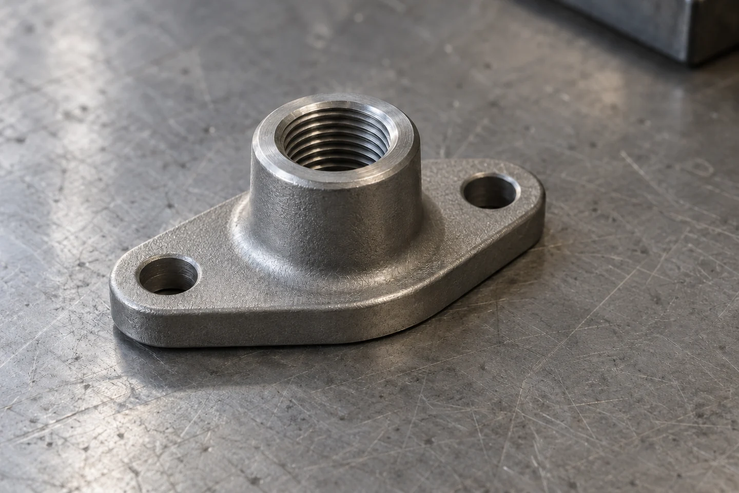
소형 하우징과 커버, 힌지 브래킷, 웨어러블 금속 프레임에서는 작은 나사 하나가 조립 위치와 접합면 압력을 동시에 유지합니다. 외관상 나사산이 선명하고 볼트가 끝까지 들어가더라도, 실제로는 유효 체결 길이가 부족하거나 볼트 끝이 홀 바닥에 먼저 닿을 수 있습니다. 따라서 나사 형상, 축력 전달 경로, 가공에 필요한 공간을 하나의 체결부로 검토해야 합니다.
금형 탈형과 소결 편차를 후가공·인서트의 비용 및 정밀도와 비교합니다.
완전한 나사산의 맞물림과 보스 벽·뿌리·좌면의 지지 능력을 함께 확인합니다.
게이지 적합성, 실제 축력, 반복 체결과 잔류 이물의 평가를 구분합니다.
1. MIM 나사 체결부의 제작 경로와 선택 기준
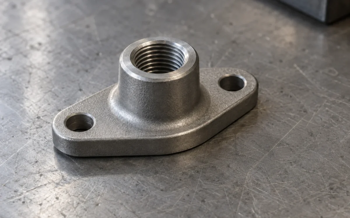
MIM은 금속 분말과 바인더로 만든 피드스톡을 금형에 사출한 뒤, 탈지와 소결을 거쳐 금속 부품을 만드는 공정입니다. 보스·리브·측벽을 일체화하기에 유리하지만, 기능 나사까지 반드시 금형에서 완성해야 하는 것은 아닙니다. 외형은 MIM으로 만들고 나사·좌면·기준 홀만 후가공하는 구성도 가능합니다.
제작 방법은 초기 금형비와 가공 단가를 함께 비교합니다. 회전 코어를 추가하여 탭 공정을 줄이더라도 금형 구조가 복잡해지고 성형 주기가 길어질 수 있습니다. 반대로 후가공은 공구와 지그, 세정·검사 비용이 추가되지만 기능 치수를 소결 이후의 기준면에서 관리할 수 있습니다.
| 제작 경로 | 우선 검토할 조건 | 설계에 반영할 제약 |
|---|---|---|
| 금형 성형 나사 | 형상 통합과 후가공 축소의 효과가 크고, 소결 후 나사 정밀도를 확보할 수 있는 조건에서 검토합니다. | 내부 나사의 회전 탈형, 외부 나사의 분할면, 성형품 손상과 소결 후 편차를 고려합니다. |
| 소결 후 절삭탭 | 소형 기능 나사의 치수·위치를 최종 가공 기준으로 관리할 때 검토합니다. | 밑구멍 편차, 칩 배출, 공구 접근, 유효 나사 깊이와 세정 공간이 필요합니다. |
| 소결 후 성형탭 | 해당 소결체의 연성과 조직이 적합하며 칩 없는 가공의 이점이 있을 때 검토합니다. | 밑구멍과 윤활에 민감합니다. 소성 변형에 따른 공구 부하와 나사 단면을 검증해야 합니다. |
| 금속 나사 인서트 | 반복 분해, 나사면의 내마모 요구, 보수성 또는 모재와 다른 나사면 특성이 필요할 때 검토합니다. | 확대된 수용나사, 잔여 벽 두께, 설치 깊이와 인서트 유지 구조가 필요합니다. |
나사 밀링은 후가공의 또 다른 선택입니다. 공구가 접근할 수 있고 장비의 원호 보간과 위치 정밀도가 충분하면 치수 보정과 칩 처리를 유연하게 구성할 수 있습니다. 다만 작은 홀에서는 공구 지름·목 길이·강성이 제한되므로 절삭탭을 항상 대체하는 방법으로 보지 않습니다.
2. 성형 나사에서 금형 분할면과 소결 수축을 다루는 방법
외부 나사와 분할면의 간섭
외부 나사는 금형의 분할 방향에 맞춰 나사 형상을 나누어 성형할 수 있습니다. 이때 분할면을 따라 생기는 단차나 플래시가 상대 나사의 진입을 방해할 수 있습니다. 나사산을 가로지르는 미세한 돌출부는 볼트를 처음 돌릴 때의 저항뿐 아니라 조립 후 접촉 분포에도 영향을 줍니다.
분할면 주변에 좁은 평탄부를 두는 방법은 금형 맞춤부와 잔흔을 관리하는 수단입니다. 그러나 평탄부의 폭과 위치는 상대 나사의 작동 구간, 요구되는 나사산 연속성 및 체결 하중과 함께 정해야 합니다. 특정 금형 사례의 평탄부 수치를 모든 나사 규격에 그대로 적용하지 않습니다.
내부 나사의 회전 탈형
내부 나사를 만드는 코어는 성형품의 나선에 걸리므로 일반적인 직선 코어처럼 그대로 인출하기 어렵습니다. 회전 코어를 사용한다면 코어가 나선 리드를 따라 회전·이동하는 동안 성형품이 함께 돌아가지 않도록 지지해야 합니다. 작은 나사에서는 코어의 강성, 구동 기구, 마모와 성형품의 취급 강도까지 금형 설계의 일부가 됩니다.
성형 직후 피드스톡의 나사 형상이 양호하더라도 최종 금속 나사로 바로 평가할 수는 없습니다. 탈지와 소결을 거친 뒤 피치·유효지름·진원도·축 방향의 변화를 확인해야 합니다. 전체 외형의 평균 수축률 하나로 모든 국부 나사 치수를 예측하는 방식은 충분하지 않습니다.
특히 긴 보스와 얇은 바닥이 연결된 구조에서는 지지 조건과 두께 변화가 소결 후 축 기울기와 위치 편차에 관여할 수 있습니다. MIM 소결 수축과 금형 보정에서 다루는 치수 관리도 최종 나사 기준면과 연결해야 합니다. 금형 단계에서 나사를 완성하는 이점은 이 편차를 포함한 공정 능력이 확보될 때 평가할 수 있습니다.
3. 소결 후 탭 가공: 밑구멍·칩·소재 상태의 연계
성형된 밑구멍의 역할
후가공 탭을 선택하면 MIM 단계에서는 보스와 밑구멍을 만들고, 소결 후 필요한 나사 형상을 가공할 수 있습니다. 다만 성형된 홀을 탭 밑구멍으로 그대로 사용할지, 드릴이나 리머 등으로 정리할지는 별도로 판단합니다. 평균 내경만 맞아도 국부적으로 작아진 구간, 테이퍼, 진원도 불량이나 축 기울기가 남을 수 있기 때문입니다.
절삭탭에서 밑구멍이 작으면 제거해야 할 재료가 늘어나고 공구 부하가 커집니다. 반대로 크면 완성 나사산 높이와 유효 전단 면적이 감소할 수 있습니다. 따라서 밑구멍은 완성 나사의 공차, 소재 상태, 공구 제조사의 적용 조건과 함께 정합니다. 소결 후 변형을 탭 자체가 무리하게 교정하도록 공정을 구성하지 않습니다.
관통공과 막힌 홀의 공구 선택
관통공용 전방 배출 방식은 칩이 홀 아래로 빠져나갈 공간이 필요합니다. 막힌 홀에서는 칩을 입구 방향으로 빼내는 공구 형상과 적절한 절삭 조건을 검토합니다. 홀 출구가 지그에 가려져 있거나 바닥에 칩이 압축되면, 도면상 관통 여부와 실제 가공 중 배출 조건이 달라집니다.
나사 유효 깊이, 탭이 들어가는 깊이, 드릴이 만드는 전체 깊이는 동일하지 않습니다. 탭 선단의 불완전 절삭 구간과 드릴 선단 형상, 칩이 머무를 공간을 포함해야 합니다. 또한 연마 입자나 가공 칩이 남으면 이후 조립 토크가 불안정해지고 나사면에 흠집이 생길 수 있으므로 세정과 건조 경로까지 검토합니다.
성형탭과 MIM 금형 성형의 구분
성형탭은 소결된 금속의 밑구멍 벽을 소성 변형시켜 나사산을 만드는 후가공입니다. 금형 안에서 피드스톡으로 나사 형상을 만드는 공정과 다릅니다. 칩 발생을 줄이는 이점은 있지만, 해당 소결체가 필요한 변형을 견딜 수 있는지가 전제입니다.
MIM 부품에는 합금명 외에도 소결 상태, 잔류 기공의 분포, 국부 결함과 열처리가 영향을 줍니다. 동일한 스테인리스 계열이라도 연성과 가공 부하는 다를 수 있습니다. 압연재나 다른 강종에서 확인한 성형탭 조건을 소형 MIM 체결부에 그대로 옮기지 않고 시험 가공으로 적용 범위를 확인해야 합니다.
성형탭의 밑구멍은 절삭탭의 밑구멍과 같은 값으로 취급하지 않습니다. 작은 밑구멍은 나사산으로 이동하는 금속량을 늘리지만 토크와 마찰열도 증가시킬 수 있습니다. 나사산 끝에는 재료 유동에 따른 분할 형상이 남을 수 있으므로 이를 나사 뿌리의 유해 균열과 구분합니다. 단면 형상, 치수, 가공 부하와 체결 성능을 함께 확인해야 합니다.
4. 유효 체결 길이와 막힌 홀의 깊이 설계
유효 체결 길이 Le는 볼트가 홀에 들어간 전체 길이와 다릅니다. 입구 모따기, 나사 시작부의 불완전 형상, 볼트 선단과 탭의 불완전 나사 구간을 제외하고 하중을 전달할 수 있는 완전한 수나사와 암나사가 실제로 겹치는 구간을 기준으로 검토합니다.
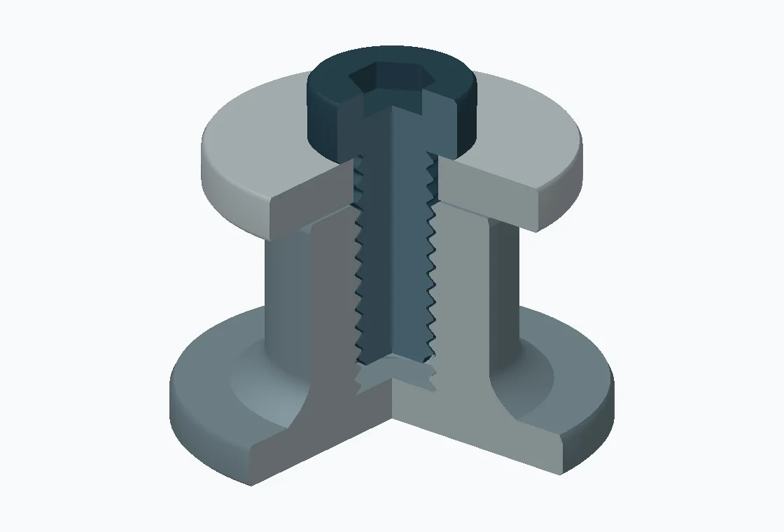
보스 외경 Db, 나사 피치 P, 잔여 벽 두께 t, 바닥 여유 C는 서로 다른 설계 변수입니다. 나사를 크게 하면 볼트 단면은 커지지만 같은 보스 외경에서 남는 벽이 줄어듭니다. 피치와 유효지름도 함께 바뀌므로 나사 호칭지름만으로 체결부 강도를 비교할 수 없습니다.
볼트 돌출 길이의 공차 누적
일반적인 머리 밑 길이 기준의 볼트를 가정하면, 볼트 길이에서 커버·와셔 등 실제 체결 적층 두께를 빼서 보스 안으로 들어가는 길이를 먼저 계산할 수 있습니다. 접시머리처럼 길이 기준이 다른 볼트는 해당 치수 정의에 맞춰 계산해야 합니다.
Lp = Ls − g
Lp는 보스 입구를 넘어가는 볼트 돌출 길이, Ls는 해당 볼트의 머리 밑 길이, g는 머리 좌면에서 보스 입구까지의 체결 적층 두께입니다. 돌출 길이에서 곧바로 유효 체결 길이를 확정하지 않고 양쪽 나사의 완전 형상 구간을 대조합니다.
최소 체결 길이는 짧은 볼트와 두꺼운 적층 조합에서 검토합니다. 반대로 바닥 간섭은 긴 볼트와 얇은 적층 조합에서 확인합니다. 두 조건을 평균 치수 하나로 합쳐 판단하면 한쪽 위험을 놓칠 수 있습니다. 와셔 두께, 코팅, 좌면의 실제 접촉 위치도 해당 적층에 포함합니다.

조임 토크가 올라가도 체결력이 확보되지 않는 경우
볼트 끝이 홀 바닥이나 불완전 나사 구간에 먼저 닿으면 회전 저항이 증가할 수 있습니다. 이때 공구는 설정 토크에 도달해도 커버가 필요한 압력으로 눌리지 않을 수 있습니다. 조립 완료 판정은 토크 값과 함께 좌면 밀착, 볼트 길이, 유효 나사 깊이를 확인해야 합니다.
바닥 여유를 확보하기 위해 구멍을 깊게 만들 때는 보스 아래의 실제 금속 두께와 주변 기능면을 함께 확인합니다. 얇은 바닥에 드릴 선단이 가까워지면 관통 불량이나 변형의 여지가 생깁니다. 나사 길이를 늘리는 조치가 새로운 박육부를 만드는지 검토해야 합니다.
5. 나사산에서 보스 뿌리까지 이어지는 하중 경로
볼트를 조이면 볼트에는 인장 축력이 생기고, 커버와 보스 좌면에는 압축력이 작용합니다. 암나사 접촉면이 받은 하중은 보스 벽과 뿌리를 거쳐 주변 바닥과 리브로 전달됩니다. 이 경로 중 어느 부분이 먼저 한계에 도달하는지에 따라 손상 형태가 달라집니다.

| 검토 위치 | 발생 가능한 현상 | 연결해서 확인할 설계 조건 |
|---|---|---|
| 볼트와 나사산 | 볼트의 과도한 인장 변형 또는 모재 나사산의 전단·손상이 발생할 수 있습니다. | 볼트 강도, 모재의 실제 상태, 유효 체결 길이와 나사 공차를 확인합니다. |
| 보스 벽과 가장자리 | 얇은 벽의 벌어짐이나 자유 가장자리 방향의 균열이 발생할 수 있습니다. | 가공 후 최소 잔여 벽, 홀 편심, 인접 홀과 외곽까지의 거리를 확인합니다. |
| 보스 뿌리와 바닥 | 체결·사용 하중의 편심으로 뿌리부 굽힘과 국부 응력이 커질 수 있습니다. | 필렛, 바닥 두께, 리브 연결, 외력 방향과 지지 조건을 확인합니다. |
| 머리 좌면과 커버 | 국부 눌림, 커버 변형과 접촉면 침하로 초기 축력이 달라질 수 있습니다. | 유효 접촉 면적, 평면도, 좌면 재질·마감 및 체결 순서를 확인합니다. |
체결 길이를 늘려도 강도가 일정 비율로 늘지 않는 이유
맞물린 각 나사산이 같은 하중을 나누어 받는 것은 아닙니다. 볼트와 모재의 탄성 변형, 나사 형상과 피치 오차에 따라 하중 분포가 달라집니다. 따라서 나사산 개수를 두 배로 늘리면 체결 강도도 두 배가 된다고 계산할 수 없습니다.
필요한 유효 체결 길이는 볼트와 모재의 상대 강도, 실제 나사 치수, 보스 형상과 사용 하중을 기준으로 정합니다. 호칭지름의 한 배 또는 한 배 반을 모든 MIM 소재에 적용하는 방식은 적절하지 않습니다. 얇은 보스가 먼저 손상된다면 나사 길이만 늘려도 해결되지 않습니다.
MIM 보스의 두께와 국부 조직
나사 주변 금속을 두껍게 하면 지지 단면을 늘릴 수 있지만, 주변 바닥과의 급격한 두께 차이가 커지면 성형·탈지·소결 관리가 어려워질 수 있습니다. 필요한 강성을 리브와 완만한 연결부로 확보하면서 홀 가공 이후의 최소 단면을 확인하는 접근이 필요합니다.
평균 밀도나 소재 성적서만으로 모든 보스의 국부 건전성을 설명할 수는 없습니다. 결함이 의심되거나 높은 체결 하중을 요구하는 부위에서는 대표 단면과 실제 부품 시험을 연계합니다. 분말 소결체의 허용 응력을 같은 합금명의 압연재 물성으로 자동 대체하지 않습니다.
6. 금속 인서트의 수용나사와 잔여 벽 설계
금속 인서트는 볼트와 접촉하는 나사면을 별도의 부품으로 구성합니다. 반복 분해와 마모, 보수 요구에 대응할 수 있지만 모재가 지지해야 할 하중은 사라지지 않습니다. 인서트 내부 나사뿐 아니라 인서트와 모재 사이의 접촉부까지 두 단계의 체결 구조로 검토합니다.
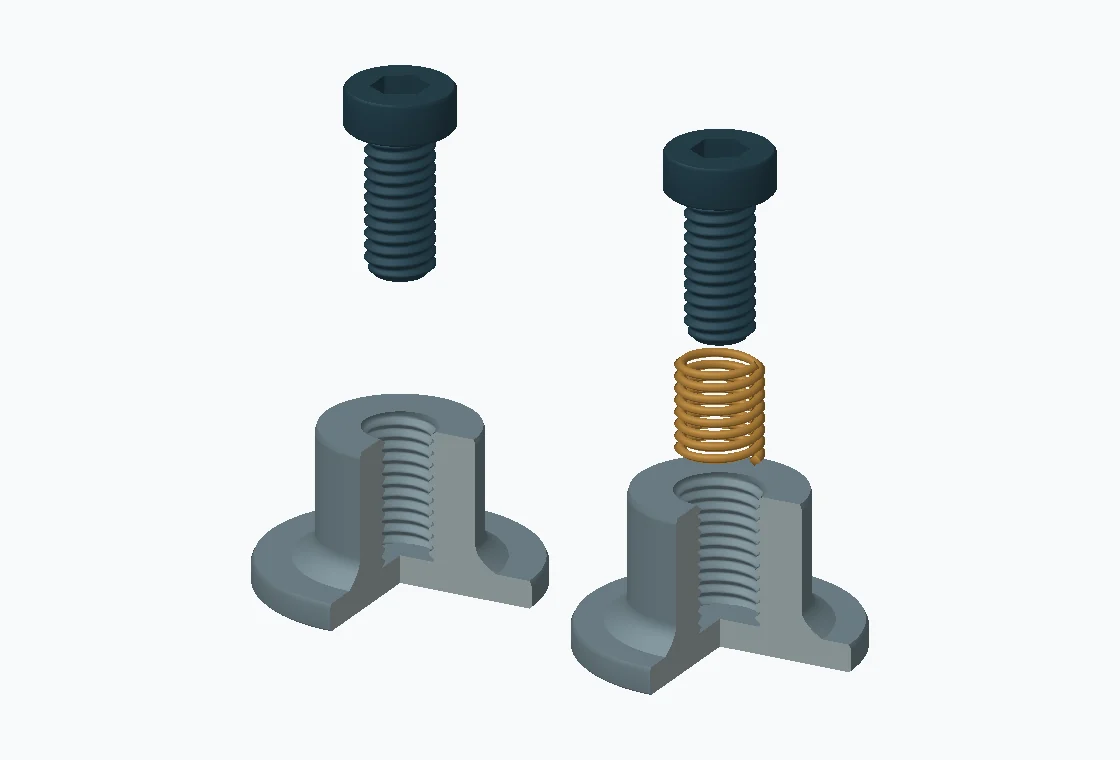
와이어 인서트와 STI 수용나사
와이어 인서트는 바깥쪽이 전용 수용나사에 맞물리고 안쪽이 볼트의 나사면을 형성합니다. 완성 볼트와 같은 규격의 일반 탭 구멍에 코일을 덧붙이는 구조가 아닙니다. 수용나사에는 해당 인서트 계열의 전용 탭과 게이지 조건을 적용합니다.
수용나사가 커지면 같은 보스 외경에서 남는 금속이 줄어듭니다. 보스 벽 두께는 최종 볼트 지름이 아니라 수용나사의 가장 바깥 형상과 보스 외면 사이의 최소 거리를 기준으로 검토합니다. 홀의 위치 편차가 있으면 한쪽 벽이 더 얇아지므로 공칭 치수만으로 계산하지 않습니다.
설치 깊이와 입구 형상은 코일이 좌면 위로 돌출하거나 볼트 진입을 방해하지 않도록 정합니다. 설치용 탱이 있는 제품은 제품별 지침에 따라 탱 제거 여부와 잔류물 관리 방법을 정하고, 무탱형은 해당 설치 공구와 절차를 적용합니다. 일반 자유 회전형과 별도의 잠금형 인서트도 구분해야 합니다. 모든 와이어 인서트에 풀림 방지 기능이 있는 것은 아닙니다.
부시형 인서트의 설치 공간
부시형 인서트는 내부 나사 밖에 인서트 자체의 벽과 외부 고정 구조가 추가됩니다. 외부나사로 고정하는 제품은 그 규격과 가공 깊이를, 키 고정형은 키가 들어가는 공간과 모재 경도를 확인합니다. 인서트 제품마다 요구 공간이 다르므로 최종 볼트 규격만으로 호환성을 판단할 수 없습니다.
고정키가 인서트의 회전을 억제하더라도 모재 나사의 인발 저항이나 보스 뿌리의 강도까지 보장하지는 않습니다. 또한 설치 공구의 접근성, 교체 시 제거 경로와 잔류 이물을 검토해야 합니다. 금속용 나사 인서트의 설계를 플라스틱용 열압입 인서트와 같은 원리로 취급하지 않습니다.
인서트의 경제성을 판단하는 단위
인서트 단가만으로 직접 탭과 비교하면 추가 탭·설치·검사·세정 비용을 놓칠 수 있습니다. 반대로 반복 조립 중 모재 나사가 손상되어 하우징 전체를 교체하는 비용도 함께 고려해야 합니다. 예상 분해 횟수와 불량 발생 시 수리 단위를 정한 뒤, 초기 공정 비용과 사용 중 유지 비용을 비교하는 것이 합리적입니다.
7. 조임 토크와 축력: 나사 강도에 앞서 확인할 접촉 조건
조임 토크는 축력을 만들어 내는 입력값입니다. 토크의 상당 부분은 나사면과 머리 좌면의 마찰에 사용되므로, 같은 토크가 언제나 같은 축력을 만드는 것은 아닙니다. 재질 조합, 표면처리, 윤활과 반복 사용에 따른 접촉면 변화가 결과에 영향을 줍니다.
T ≈ K · Fp · d
T는 조임 토크, Fp는 초기 축력, d는 볼트 호칭지름입니다. K는 마찰과 접촉 조건을 포함하는 경험 계수로, 마찰계수 하나와 동일하지 않습니다. 이 근사 관계에 임의의 일정값을 넣어 미검증 MIM 체결부의 허용 토크를 정하지 않습니다.
같은 토크에서 마찰이 낮아지면 축력이 증가할 수 있으므로, 윤활이나 코팅 변경을 조립성 개선으로만 볼 수 없습니다. 반대로 마찰이 높아지면 설정 토크에 도달했어도 필요한 축력을 얻지 못할 수 있습니다. 스테인리스 접촉부의 응착·갤링은 단순히 토크를 높여 해결할 문제가 아니며 소재 조합과 표면·윤활 조건을 함께 검토합니다.
설계 목표는 사용 중 접합면이 벌어지거나 미끄러지지 않도록 필요한 최소 축력을 유지하면서, 조립 시 최대 축력이 볼트·모재 나사·보스·좌면의 한계를 넘지 않게 하는 것입니다. 외력에 따른 볼트 하중 증가는 접합부와 볼트의 상대 강성 및 외력 도입 위치에 영향을 받습니다. 외력 전체를 초기 축력에 단순 합산하는 방식만으로 설계를 끝내지 않습니다.
반복 조립과 풀림 현상의 구분
처음 체결할 때와 반복 체결할 때는 접촉면 상태가 같지 않을 수 있습니다. 코팅 마모, 윤활 변화, 미세한 눌림과 이물에 의해 토크와 축력의 관계가 달라집니다. 반복 분해 제품에서는 최초 조임뿐 아니라 정해진 반복 횟수 이후의 조립 조건으로 확인해야 합니다.
축력 감소도 모두 나사가 회전해서 풀린 결과는 아닙니다. 좌면과 접합면의 침하 또는 국부 변형으로 회전 없이 축력이 줄 수 있습니다. 진동에 따른 회전 풀림, 접촉면 침하, 나사면 손상과 인서트 이동을 구분하여 대책을 정합니다. 잠금 기능을 추가해도 부족한 좌면 강성이나 잘못된 볼트 길이를 대신 해결하지는 못합니다.
8. 나사 게이지 검사와 체결 성능 시험의 역할
나사 플러그 게이지는 지정된 나사 공차에 대한 적합성을 확인하는 도구입니다. 토크와 축력, 인발 저항, 반복 수명을 직접 측정하는 도구는 아닙니다. 게이지에 맞는 나사라도 얇은 보스, 국부 결함 또는 부족한 유효 체결 길이 때문에 실제 조립에서 손상될 수 있습니다.
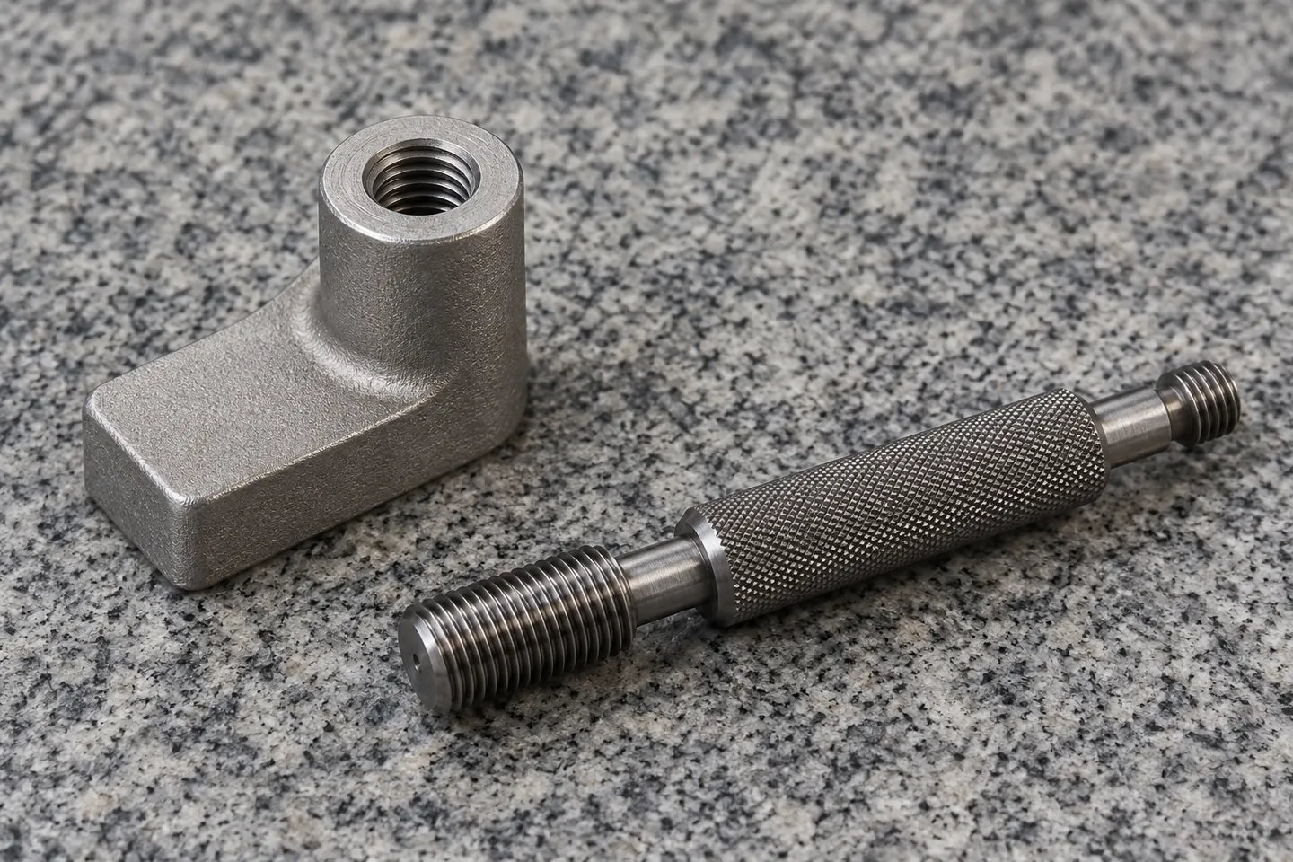
치수 검사에서 놓치기 쉬운 항목
GO·NO-GO 나사 게이지의 판정은 적용 나사 규격과 게이지 절차에 맞춰 수행합니다. 구멍 깊이와 입구 형상, 나사 축의 위치·기울기, 좌면과의 관계는 별도로 확인할 수 있어야 합니다. 인서트가 있는 부품은 설치 전 수용나사와 설치 후 완성 나사를 각각 해당 절차로 평가합니다.
완성 볼트가 들어간다는 사실만으로 나사 공차가 검증되지는 않습니다. 볼트는 상대 부품이지 교정된 검사 게이지가 아니며, 특정 볼트와의 우연한 맞물림이 양산 호환성을 대신하지 못합니다. 버나 잔류 칩으로 진입 저항이 생겼다면 게이지를 억지로 밀어 넣기 전에 원인을 확인합니다.
| 평가 구분 | 확인할 결과 | 구분해서 기록할 조건 |
|---|---|---|
| 치수·형상 | 게이지 적합성, 유효 깊이, 축 위치와 좌면 관계를 확인합니다. | 금형 캐비티, 소결 로트, 공구 사용 구간 및 후처리 상태를 구분합니다. |
| 조임 과정 | 토크·회전각·좌면 밀착을 관찰하고 필요하면 축력을 직접 측정합니다. | 볼트·와셔·윤활·코팅, 조임 속도와 체결 순서를 고정합니다. |
| 한계 하중 | 나사산 손상, 인서트 이동, 보스 균열 등 실제 파손 위치를 확인합니다. | 축방향 인장과 조임 파괴 시험의 하중 경로 차이를 구분합니다. |
| 반복 조립·사용 | 반복 후 진입성, 토크 변화, 잔류 축력과 나사면 손상을 확인합니다. | 실제 분해 조건과 사용 환경을 반영하고 재사용 부품의 범위를 정합니다. |
시험의 경계 조건과 파손 형태
볼트를 회전시켜 조임 한계까지 평가하는 시험과 체결부를 축방향으로 당기는 시험은 같은 시험이 아닙니다. 전자는 마찰과 조립 과정의 영향을 포함하고, 후자는 지그의 지지 위치와 하중 도입 방식에 영향을 받습니다. 시험 지그가 실제 제품보다 보스를 강하게 감싸면 실제 사용과 다른 파손 결과가 나올 수 있습니다.
최대 하중 숫자만 남기지 않고 파손 위치, 나사산 전단 여부, 보스의 균열 방향과 인서트 이동을 함께 기록합니다. 소결 로트·캐비티·공구 수명 구간을 분리해 확인하면 소재 편차와 가공 편차를 구분하기 쉽습니다. 합격 기준과 시료 수는 제품 위험도와 요구 신뢰도에 맞춰 정하며 임의의 공통 숫자로 대체하지 않습니다.
검증 기준으로는 ISO 1502의 나사 게이지 체계와 ISO 16047의 토크·축력 시험 개념을 참고할 수 있습니다. 다만 소형 나사, 소재 조합과 잠금 기능 등 실제 시험품이 해당 표준의 범위에 들어가는지 먼저 확인해야 합니다. 표준 번호를 적는 것만으로 특정 MIM 체결부의 내구성이 입증되는 것은 아닙니다.
9. 도면과 양산 공정에 남겨야 할 설계 정보
나사 호칭과 깊이만 지정하면 제작자는 가공 가능 여부를 검토할 수 있지만, 조립 조건과 사용 중 요구를 완전히 판단하기 어렵습니다. 기능면의 기준과 실제 볼트·커버의 조합을 함께 전달해야 후가공 범위와 검사 방법을 일치시킬 수 있습니다.
| 설계 정보 | 도면·사양에 연결할 내용 |
|---|---|
| 소재와 상태 | MIM 합금, 열처리와 표면처리 상태, 체결부에서 요구되는 물성·조직 조건을 명시합니다. |
| 나사와 기준 | 호칭·피치·공차 등급·유효 나사 구간, 기준면에 대한 홀 위치와 축 방향을 지정합니다. |
| 조립 적층 | 볼트 길이, 커버·와셔 두께, 좌면, 최소 체결 길이와 최대 삽입 시 바닥 여유를 대조합니다. |
| 주변 지지 구조 | 가공 후 최소 벽, 가장자리 거리, 보스 필렛과 바닥 두께를 확인합니다. |
| 인서트 적용 | 제품 계열과 설치 길이, 수용나사, 설치 깊이·방향, 잠금·탱 처리와 검사 조건을 지정합니다. |
| 조립·검증 조건 | 표면·윤활 상태, 조임 관리 방식, 재사용 범위, 기능·강도·수명 평가를 연결합니다. |
공정 순서는 소재 상태와 최종 기능에 따라 정합니다. 열처리 전 가공은 공구 부하를 줄일 수 있지만 이후 치수 변화가 남을 수 있고, 열처리 후 가공은 완성 치수 관리에 유리한 대신 공구 선택과 가공 부하가 달라집니다. 코팅이 나사와 좌면에 적용되면 치수뿐 아니라 마찰 조건도 다시 확인합니다.
초기 검토에서는 조립 하중과 반복 분해 요구를 정의하고, 보스가 허용하는 공간을 확인한 뒤 제작 경로를 좁혀 갑니다. 시험 가공과 실제 조립 시험으로 기능을 검증한 다음, 그 결과를 밑구멍·공구·세정·검사 조건에 반영합니다. MIM 나사 체결부의 완성도는 나사산 하나의 정밀도와 주변 구조의 지지 능력이 함께 확보될 때 결정됩니다.
English edition
A threaded connection in a metal injection molded component must provide both a usable thread and a structure capable of carrying the assembly load. Choosing a molded thread, a post-sintering tapped thread or a metal insert requires more than the nominal screw size. Required preload, disassembly conditions, dimensional variation after sintering and the remaining metal around the boss must be considered together.
In small housings, covers, hinge brackets and wearable metal frames, a screw can maintain both assembly position and pressure at the joint interface. A clearly defined thread that accepts a screw may still have insufficient effective engagement, or the screw tip may contact the bottom before the cover is clamped. Thread geometry, the load path and the space required for manufacturing therefore belong to the same design problem.
1. Manufacturing routes for MIM threaded connections
MIM combines metal powder and binder into a feedstock, injection molds the shape, and removes the binder before sintering. It can integrate bosses, ribs and walls, but the functional thread does not necessarily have to be completed in the mold. An alternative is to produce the main body by MIM and machine only the threads, bearing faces and reference holes.
Tooling investment and recurring manufacturing cost should be compared together. An unscrewing core may eliminate tapping while increasing mold complexity and the molding cycle. Secondary machining introduces tools, fixtures, cleaning and inspection, but allows functional dimensions to be established from reference surfaces after sintering.
- Molded threads: Consider them when feature integration and reduced secondary machining justify the tooling, and the required thread accuracy can be maintained after sintering. Demolding, parting-line marks and damage to the molded part require attention.
- Cut tapping after sintering: Consider it when thread size and position need to be controlled from final machining references. Pilot-hole variation, chip evacuation, tool access, effective depth and cleaning space remain important.
- Form tapping after sintering: Consider it when the actual sintered material has suitable ductility and microstructure. Chipless processing must be balanced against sensitivity to pilot-hole size, lubrication and forming load.
- Metal thread inserts: Consider them for repeated disassembly, wear resistance, repair requirements or a thread surface different from the parent material. Receiving threads, residual wall thickness and installation space must be included.
Thread milling provides another secondary machining option. With adequate tool access, circular interpolation and positioning accuracy, it can offer flexibility in diameter adjustment and chip control. In small holes, cutter diameter, neck length and stiffness limit its application, so it is not an automatic substitute for tapping.
2. Mold parting and sintering shrinkage in molded threads
External threads and parting-line interference
External threads can be divided between mold members according to the opening direction. A step or flash along the parting line can interfere with the mating thread. A small protrusion crossing the thread profile can affect both the initial turning resistance and the contact distribution after assembly.
Narrow flats near the parting line can help control mold shut-off and witness marks. Their position and width must nevertheless be compatible with the working portion of the mating thread, the required continuity of the profile and the connection load. Dimensions from one mold example should not be applied indiscriminately to other thread sizes.
Unscrewing an internal thread core
An internal thread mechanically engages its molding core, preventing ordinary straight withdrawal. With an unscrewing core, the molded part must be restrained while the core rotates and translates along the thread lead. Core stiffness, drive design, wear and the handling strength of the molded part are particularly relevant for small threads.
A satisfactory feedstock thread immediately after molding is not yet a finished metal thread. Pitch, pitch diameter, roundness and axis direction must be checked after debinding and sintering. A single average shrinkage factor for the overall component cannot adequately describe every local thread dimension.
Support conditions and thickness transitions can influence the final position and inclination of a long boss attached to a thin floor. Mold compensation and sintering control must therefore relate to the final thread references. The benefit of completing the thread in the mold depends on process capability that includes these sources of variation.
3. Post-sintering tapping: pilot holes, chips and material condition
The role of the molded pilot hole
A MIM boss and pilot hole can be produced first, followed by tapping after sintering. Whether the molded hole can be used directly or requires drilling, reaming or another finishing operation is a separate decision. An acceptable average diameter may conceal a locally restricted section, taper, out-of-roundness or an inclined axis.
For cut tapping, a smaller pilot hole increases the material to be removed and the tool load. An oversized hole can reduce thread height and the effective area available to resist stripping. Select the pilot hole with reference to the final thread tolerance, material condition and tool recommendations. The tap should not be expected to correct substantial distortion left by sintering.
Through holes and blind holes
A forward chip-ejection strategy requires a clear exit below the hole. Blind-hole machining requires suitable tool geometry and conditions for removing chips toward the entrance. Even a nominally through hole can behave differently if its exit is obstructed by the fixture. Compacted chips can increase torque and contribute to tool failure.
Effective thread depth, tap travel and total drilled depth are distinct. The incomplete cutting region at the tap lead, the drill-point geometry and chip space must be allowed for. Cleaning and drying also matter: retained chips or abrasive particles can destabilize assembly torque and damage thread surfaces.
Form tapping is different from molding a thread
Form tapping creates an internal thread by plastically displacing the wall of a hole in already sintered metal. It is not the same process as shaping feedstock in a MIM mold. Reduced chip generation is useful only if the actual sintered material can tolerate the required deformation.
Alloy designation alone is insufficient. Sintered condition, the distribution of residual pores, local defects and heat treatment can change ductility and machining load. Conditions established for wrought material or another steel should not be transferred directly to a small MIM connection. Trial machining is needed to establish the applicable range.
The pilot-hole diameter for a forming tap must not be treated as interchangeable with that for a cutting tap. A smaller hole increases the amount of displaced metal but can also increase torque and frictional heating. Material flow may leave a split profile at the thread crest; this must be distinguished from a harmful crack at the root. Cross-sectional geometry, dimensions, machining load and connection performance should be assessed together.
4. Effective engagement and blind-hole depth
Effective engagement length, Le, is not the total distance a screw enters a hole. It is based on the actual overlap of complete external and internal thread profiles capable of transferring load. Entrance chamfers, incomplete starts, the screw-tip geometry and the tap’s incomplete thread region must be excluded as appropriate.
Boss outside diameter Db, pitch P, remaining wall thickness t and bottom clearance C represent different design variables. Increasing screw diameter increases its section but removes metal from a boss of unchanged outside diameter. Pitch and pitch diameter also matter, so nominal diameter alone cannot establish connection strength.
Tolerance accumulation in screw projection
For a screw whose length is specified beneath the head, subtract the assembled cover, washer and other relevant stack thicknesses to estimate its projection into the boss. A countersunk screw or another length convention requires the corresponding dimensional definition.
Lp = Ls − g
Lp is the screw projection beyond the boss entrance, Ls is the under-head screw length and g is the assembled thickness between the head bearing surface and the boss entrance. Projection does not establish effective engagement by itself; compare the complete thread regions on both members.
Check minimum engagement using the short-screw and thick-stack combination. Check bottom interference using the long-screw and thin-stack combination. Evaluating only nominal dimensions can miss one of these limits. Washer thickness, coatings and the actual bearing locations belong in the relevant stack.
Increasing torque without adequate clamping
If the screw contacts the hole bottom or an incomplete thread region first, turning resistance may increase before the cover is adequately clamped. A tool can then reach its torque setting without producing the required joint pressure. Assembly evaluation should include seating, screw length and effective thread depth.
Deepening the hole to create clearance also affects the metal remaining beneath the boss and nearby functional surfaces. A drill point approaching a thin floor can create a risk of unintended breakthrough or deformation. Extending thread length should therefore be checked for new thin sections elsewhere in the component.
5. The load path from thread flanks to the boss root
Tightening develops tensile preload in the screw and compression through the cover and bearing surfaces. Load received by the internal thread passes through the boss wall and root into the surrounding floor and ribs. The first limiting location determines the resulting damage mode.
- Screw and engaged threads: Excessive screw elongation or stripping of the parent-material thread requires examination of screw strength, material condition, engagement and thread tolerances.
- Boss wall and free edges: Wall opening or cracking toward an edge requires examination of the minimum machined wall, hole eccentricity and distances to adjacent holes and boundaries.
- Boss root and floor: Eccentric assembly or service loads can increase local bending. Fillets, floor thickness, rib connections and support conditions influence this region.
- Head bearing surface and cover: Local indentation, cover deformation and settling can change preload. Contact area, flatness, material, finish and tightening sequence all contribute.
Engagement length and nonuniform load sharing
Engaged thread turns do not necessarily share load equally. Elastic deformation of the screw and parent material, thread geometry and pitch errors influence the distribution. Doubling the number of engaged turns therefore does not imply twice the connection strength.
Required engagement depends on the relative strengths of the screw and parent material, actual thread dimensions, boss geometry and service loading. A universal engagement of one or one-and-a-half nominal diameters is inappropriate for all MIM materials. Additional engagement cannot by itself correct a boss wall that fails first.
Wall transitions and local integrity
More metal around a hole can increase the supporting section, but an abrupt thickness difference relative to the surrounding floor can complicate molding, debinding and sintering. Ribs and gradual transitions can be considered while preserving the minimum section remaining after machining.
Average density or a material certificate alone does not establish the local integrity of every boss. Suspected defects or demanding assembly loads may require representative sections combined with component testing. Allowable stresses for a sintered material should not automatically be replaced by wrought-material properties carrying the same alloy name.
6. Receiving threads and wall thickness for metal inserts
A metal insert provides a separate surface for contact with the screw. It can address wear, repeated disassembly and repair needs, but the parent material still carries the load. Both the screw-to-insert interface and the insert-to-parent-material interface must be assessed.
Wire inserts and STI receiving threads
A wire insert engages a dedicated receiving thread on its outside while forming the screw thread on its inside. It is not a coil added to an ordinary tapped hole of the final screw size. Use the tap and gauge requirements specified for the insert system.
The enlarged receiving thread reduces the remaining metal in a boss of fixed outside diameter. Assess the minimum distance from the outermost receiving-thread geometry to the boss surface, rather than using the final screw diameter. Position error can make one wall thinner than its nominal value suggests.
Installation depth and entrance geometry must prevent the coil from protruding above the bearing face or obstructing entry. For products with an installation tang, follow the product-specific instructions to determine whether removal is required and how retained material is managed. Tangless products require their corresponding tools and procedures. Free-running and locking versions must also be distinguished. A wire insert does not inherently provide a screw-locking function.
Space required by solid bushing inserts
A bushing insert adds its own wall and external retention structure around the internal thread. Externally threaded products require their specified receiving thread and machining depth. Key-locking products additionally require space for the keys and a compatible parent-material condition. Final screw size alone does not establish interchangeability between insert systems.
Keys that resist insert rotation do not establish the pull-out strength of the parent thread or the strength of the boss root. Installation-tool access, the removal path for replacement and retained debris also require attention. Metal insert installation must not be treated as equivalent to heat-setting a threaded insert into a thermoplastic.
Comparing costs over the connection’s use
Comparing only the insert purchase price with direct tapping omits receiving-thread machining, installation, inspection and cleaning. Conversely, damage to an integral thread may require replacement of the entire housing. Compare initial manufacturing and maintenance costs after defining expected disassembly conditions and the repair unit.
7. Tightening torque, preload and contact conditions
Tightening torque is an input used to generate preload. Much of it is consumed by friction at the threads and beneath the head, so identical torque does not necessarily produce identical preload. Material pairing, coatings, lubrication and changes from repeated use affect the relationship.
T ≈ K · Fp · d
T is tightening torque, Fp is initial preload and d is nominal screw diameter. K is an empirical factor incorporating friction and contact conditions; it is not a single friction coefficient. An assumed constant must not be used to assign allowable torque to an unverified MIM connection.
Lower friction can increase preload at the same torque. Lubrication or coating changes therefore require more than an assessment of easier assembly. Higher friction can produce the opposite result, reaching the torque setting before the necessary preload develops. Galling in stainless contacts requires examination of material pairing and surface and lubrication conditions, rather than simply increasing torque.
The design must retain sufficient clamping against separation or slip in service while keeping maximum assembly preload within the limits of the screw, parent threads, boss and bearing surfaces. Additional screw load under external loading depends on the relative stiffness of the joint and screw and on where the load enters. Simply adding the entire external load to initial preload is insufficient.
Repeated assembly and different causes of preload loss
Initial and repeated assembly may involve different contact conditions. Coating wear, lubricant changes, local indentation and debris can alter the torque–preload relationship. Products intended for disassembly should therefore be evaluated after the specified reuse sequence as well as at first assembly.
Preload loss does not always mean rotational loosening. Settling and local deformation can reduce preload without screw rotation. Distinguish vibration-induced rotation, contact settling, thread damage and insert movement before choosing a remedy. A locking feature cannot compensate for inadequate bearing stiffness or incorrect screw length.
8. Thread gauging and connection-performance testing
A thread plug gauge assesses conformity with specified thread tolerances. It does not directly measure preload, pull-out resistance or service life. A gauged thread can still fail in assembly because of a thin boss, a local defect or insufficient effective engagement.
Dimensional checks beyond screw fit
Apply GO and NO-GO acceptance according to the relevant thread specification and gauging procedure. Depth, entrance form, axis position and inclination, and the relationship to bearing surfaces need appropriate checks of their own. For an insert connection, evaluate the receiving thread before installation and the final thread afterward using the applicable procedures.
A screw entering the hole does not verify thread tolerances. It is a mating component rather than a calibrated gauge, and one favorable pairing does not establish production interchangeability. If burrs or chips cause resistance, investigate before forcing the gauge into the hole.
- Dimensions and geometry: Check gauging, effective depth, axis location and bearing relationships, with mold cavity, sintering lot, tool-use interval and post-treatment condition recorded.
- Tightening: Observe torque, rotation and seating, and measure preload directly when necessary. Control screw, washer, lubricant, coating, tightening speed and sequence.
- Limiting load: Identify thread stripping, insert displacement and boss cracking. Distinguish axial tensile testing from tightening-to-failure testing.
- Repeated assembly and service: Examine entry behavior, torque change, residual preload and surface damage after the relevant sequence, with reused components explicitly defined.
Test boundaries and failure modes
A test that rotates a screw to a tightening limit is different from pulling the connection axially. The former includes friction and the assembly process; the latter depends on fixture support and load introduction. A fixture that constrains the boss more strongly than the actual product may produce an unrepresentative failure mode.
Record failure location and mechanism alongside maximum load. Separating sintering lots, mold cavities and tool-life intervals helps distinguish material variation from machining variation. Acceptance limits and sample numbers should follow product risk and reliability requirements rather than arbitrary universal values.
The thread-gauging framework of ISO 1502 and torque–clamp-force testing concepts of ISO 16047 can inform verification. Confirm that the actual thread size, material combination and locking features fall within the applicable scope. Citing a standard number alone does not establish the durability of a particular MIM connection.
9. Information to retain in drawings and production specifications
A thread designation and depth allow an initial manufacturing assessment but do not fully describe assembly and service requirements. Functional references and the actual screw–cover combination are needed to align secondary machining and verification.
- Material condition: Specify the MIM alloy, heat treatment, surface treatment and relevant property or microstructural requirements.
- Thread and references: Define designation, pitch, tolerance class, the effective thread region, and hole position and axis direction relative to datums.
- Assembly stack: Compare screw length, cover and washer thicknesses, bearing surfaces, minimum engagement and bottom clearance at maximum insertion.
- Supporting structure: Check the minimum machined wall, edge distances, boss fillets and floor thickness.
- Insert specification: Identify the system, installed length, receiving thread, depth, direction, locking or tang provisions, and inspection requirements.
- Assembly and validation: Connect surface and lubrication conditions, tightening control, reuse limits, and functional, strength and life evaluations.
Process sequence depends on material condition and final function. Machining before heat treatment can reduce tool loading but leave subsequent dimensional changes to manage. Machining afterward can help control final dimensions while changing tool requirements and loads. Coatings on threads or bearing surfaces require renewed attention to both dimensions and friction.
Development should begin with assembly loads and disassembly requirements, followed by the available boss space and a comparison of manufacturing routes. Trial machining and representative assembly testing then establish the conditions to retain for pilot holes, tools, cleaning and inspection. A successful MIM threaded connection combines accurate thread geometry with adequate support throughout the surrounding structure.
추가 정보
주제 요약
MIM 나사 체결부는 금형 성형·후가공 탭·금속 인서트의 제작 조건과 실제 조립 하중을 함께 검토합니다. 완전한 나사산의 유효 맞물림, 막힌 홀의 바닥 여유, 보스의 잔여 벽과 뿌리 구조를 확인하고, 치수 적합성과 체결 성능을 별도로 검증합니다.
핵심 포인트
- 내부 성형 나사는 회전 탈형의 복잡성과 소결 후 정밀도를 후가공 탭과 비교합니다.
- 소결 후 성형탭은 금형 성형과 다르며 소재의 연성·조직·밑구멍 조건을 확인합니다.
- 홀 깊이와 볼트 삽입 길이가 같아도 유효 체결 길이는 다를 수 있습니다.
- 인서트는 전용 수용나사와 모재의 최소 잔여 벽을 기준으로 설계합니다.
- 조임 토크, 축력, 게이지 적합성 및 반복 조립 내구성은 서로 다른 평가 항목입니다.
자주 묻는 질문
MIM 나사는 반드시 소결 후 탭 가공해야 합니까?
금형에서 내·외부 나사 형상을 성형하는 방법도 가능합니다. 다만 탈형 구조, 분할면 흔적, 소결 후 나사 정밀도와 생산 수량을 검토하여 후가공과 경제성을 비교합니다. 기능 나사를 최종 가공 기준에서 관리해야 한다면 후가공을 검토합니다.
나사 길이가 호칭지름보다 길면 충분합니까?
호칭지름과의 비율만으로 충분한 체결 강도를 확정할 수 없습니다. 완전한 나사산의 실제 겹침, 볼트와 모재의 강도, 보스 벽·뿌리·좌면과 사용 하중을 함께 확인합니다.
인서트를 넣으면 체결부가 항상 강해집니까?
나사면의 내마모성과 반복 조립 특성을 개선하는 방안이 될 수 있지만 모재의 지지 능력은 별도로 필요합니다. 수용나사 가공 후 남는 벽이 부족하거나 보스 뿌리가 약하면 다른 위치에서 파손될 수 있습니다.
나사 게이지에 합격하면 조립 토크도 확정할 수 있습니까?
게이지는 지정 나사의 치수 적합성을 평가합니다. 허용 조립 조건은 마찰·표면·윤활, 실제 축력, 볼트와 모재의 한계 및 반복 사용을 반영하여 별도로 정합니다.
설계 검토에 필요한 정보는 무엇입니까?
부품 도면, MIM 소재와 열처리 상태, 나사 규격·공차, 볼트와 커버의 적층, 사용 하중과 반복 분해 횟수가 필요합니다. 인서트를 사용하는 경우 제품 계열과 설치 요구를 함께 전달합니다.
관련 기술자료
관련 태그

Related posts
미용기기 교체형 금속 헤드: 베요넷 잠금 구조의 가공과 조립

이어폰 충전케이스 힌지: 플라스틱 내부 장착과 MIM 정밀부품 설계

미용기기 MIM 선택 코팅: 외관면·전기 접점·조립면의 정밀 설계
미용기기 MIM 헤드: 접촉 곡면·모서리·조립 단차의 정밀 제조