MIM 경면 품질: 금속 외장의 미세 기공과 소결·연마 공정 설계
MIM 경면 품질: 금속 외장의 미세 기공과 소결·연마 공정 설계
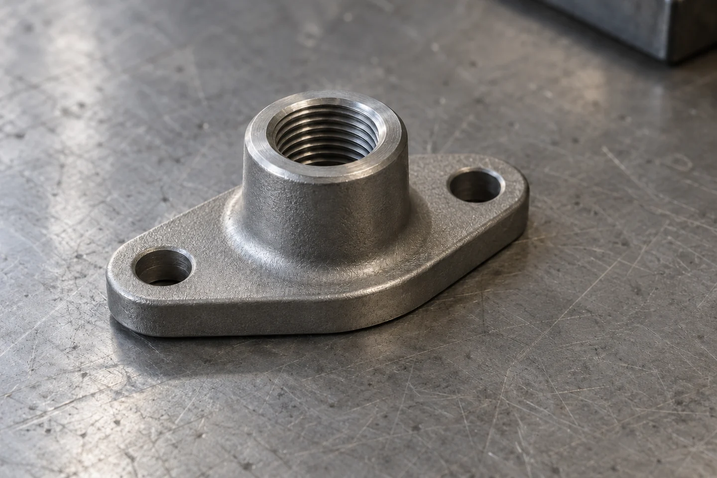
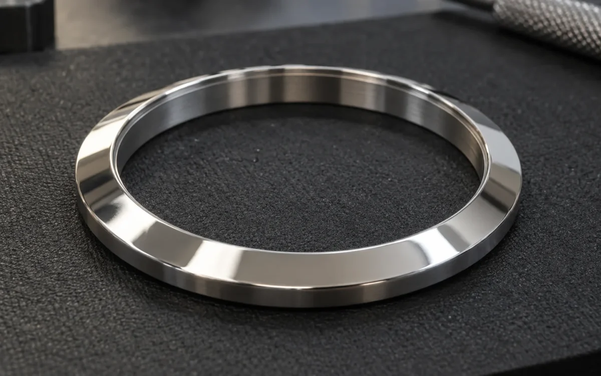
MIM 경면 품질은 마지막 버핑 단계에서만 결정되지 않습니다. 분말사출성형으로 만든 금속 외장은 미세 요철의 감소로 반사 선명도를 높일 수 있지만, 표면 아래의 기공이 드러나거나 모서리 형상이 손실될 수 있습니다. 최종 외관면이 놓일 깊이까지 소재의 치밀화 상태와 연마 여유를 함께 설계해야 합니다.
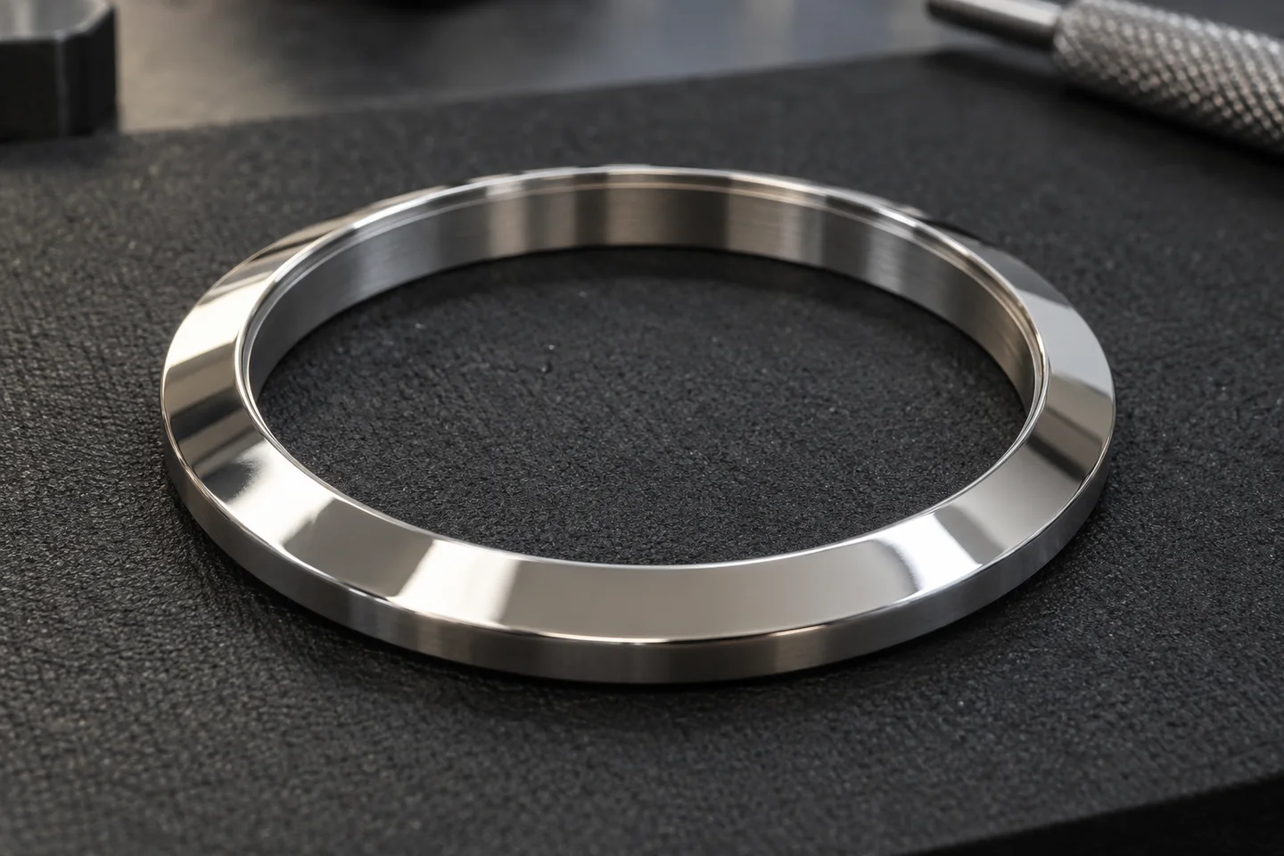
시계 베젤, 웨어러블 프레임, 미용기기 금속 헤드처럼 빛의 반사가 제품 인상을 만드는 부품은 작은 함몰에도 민감합니다. 무광 상태에서 눈에 띄지 않던 결함이 경면에서 검은 점처럼 보이기도 합니다. 이때 연마 시간을 늘리기 전에 기존 기공의 노출인지, 입자 탈락인지, 기공을 덮던 금속막이 제거된 것인지를 구분해야 합니다.
평균 밀도와 함께 외관면 근처의 기공 크기·분포·연결성을 확인합니다.
흠집 제거에 필요한 연마량을 두께·단차·에지의 허용 여유와 연결합니다.
거칠기, 국부 결함, 반사 형상과 조립 치수를 각각 평가합니다.
1. MIM 경면 품질을 결정하는 표면의 네 가지 상태
경면은 빛이 강하게 반사되는 상태만을 뜻하지 않습니다. 반사된 선이 휘어지거나, 미세한 산란으로 뿌옇게 보이거나, 국부적인 점 결함이 남아 있으면 같은 광택 수준에서도 외관 평가는 달라집니다. 표면을 전체 형상, 파상도, 미세 거칠기, 국부 결함으로 나누어 보는 이유입니다.
전체 형상과 비교적 긴 파장의 굴곡은 반사상의 모양에 영향을 줍니다. 더 짧은 길이 범위의 요철은 표면의 미세 질감과 산란에 관여합니다. 핀홀처럼 드물게 존재하는 깊은 함몰은 평균 거칠기와 별도의 결함으로 관리해야 합니다.
따라서 도면에 ‘경면’ 또는 ‘Ra 이하’만 적으면 제작자와 검사자가 서로 다른 결과를 합격으로 해석할 수 있습니다. 외관 중요면, 관찰 조명과 각도, 허용되는 점 결함, 유지해야 할 모서리와 조립면을 함께 정해야 합니다. 곡면은 자체 곡률에 의해 반사상이 변하므로 설계 형상에서 예상되는 반사와 국부적인 표면 굴곡도 구분합니다.
2. 연마가 진행될 때 내부 기공이 드러나는 원리
MIM은 금속 분말과 바인더를 혼합한 피드스톡을 사출하고, 바인더를 제거한 뒤 소결하여 금속 골격을 치밀화하는 공정입니다. 최종 부품에 남는 기공은 분말의 충전 상태, 성형 균일성, 탈지 경로와 소결 이력의 영향을 받습니다. 소결 후의 표면 상태만으로 더 깊은 위치의 기공 분포를 알 수는 없습니다.
표면 아래에 닫혀 있던 기공은 연마로 재료가 제거되어 새로운 표면과 교차하면 외부로 열립니다. 연마 전에는 보이지 않던 점이 연마 후 나타났더라도, 연마가 그 위치에 새로운 내부 기공을 만들었다고 바로 해석할 수는 없습니다.

제거량과 개구 크기의 관계
구형 기공을 가정하면 이 관계를 기하학적으로 설명할 수 있습니다. 원래 표면에서 기공 중심까지의 깊이를 z, 기공 반지름을 r, 제거 깊이를 t라고 할 때, 새 표면이 기공과 교차하는 구간의 개구 반지름 a는 다음과 같습니다.
a = √[r² − (z − t)²] (|z − t| < r)
구형 기공과 평면 제거를 가정한 설명 모델입니다. 실제 기공 형상, 연결성, 연마 중 소성 유동과 입자 탈락까지 예측하는 제품 판정식은 아닙니다.
제거면이 기공 중심에 가까워질 때 개구가 커지고, 중심을 지나면 작아질 수 있습니다. 해당 기공을 완전히 제거할 깊이까지 가공하면 그 기공은 사라질 수 있지만, 다른 깊이에 있던 기공이 새로 나타날 수도 있습니다. 그 과정에서 두께와 외곽 치수의 여유도 소모됩니다.
연마량을 늘리면 표면 결함이 일정하게 감소한다는 가정은 성립하지 않습니다. 소결체의 표면이 내부보다 항상 치밀하다는 가정도 사용할 수 없습니다. 외관면 위치와 실제 제거 깊이에 맞춘 관찰이 필요합니다.
같은 공극률에서도 개구 크기와 개수가 달라지는 이유
밀도는 기공이 차지하는 전체 체적을 반영하지만, 그 체적이 몇 개의 기공에 나뉘어 있는지는 직접 알려주지 않습니다. 이 차이는 단순한 기하학으로도 설명할 수 있습니다. 반지름이 모두 r인 서로 겹치지 않는 구형 기공이 균일하게 분포하고 경계 효과를 무시하는 모델에서, 기공의 체적분율을 φ, 단위 체적당 기공 수를 NV라고 하면 다음 관계가 성립합니다.
NV = 3φ / (4πr³)
NA = 2rNV = 3φ / (2πr²)
NA는 평면 단면의 단위 면적과 교차하는 기공 수의 기댓값입니다. 단면 양쪽으로 반지름 r 이내에 중심이 있는 기공이 단면과 만난다는 조건에서 얻습니다.
이 모델에서는 공극률이 같아도 작은 기공이 많이 분산된 조직과 큰 기공이 적게 존재하는 조직의 단면 관찰 결과가 달라집니다. 따라서 기공의 개수만 줄었다는 이유로 치밀화가 개선되었다고 판단할 수 없으며, 개수·개구 크기·면적분율을 함께 확인해야 합니다. 관찰 장비가 작은 기공을 검출하지 못하면 실제 분포와 검출된 개수의 관계도 달라집니다.
실제 MIM 부품에는 크기 분포, 기공 군집, 연결된 통로와 표면 근처의 밀도 차이가 있습니다. 위 관계를 실제 부품의 핀홀 불량률 계산식으로 사용하지 않고, 평균 밀도·단면 기공 수·최대 결함 크기가 서로 다른 정보를 제공한다는 점을 설명하는 기준으로 사용합니다.
단면 형상과 최종 표면 깊이의 해석
기공의 단면이 둥글게 보인다는 이유만으로 외부와 완전히 차단된 폐기공이라고 판정할 수는 없습니다. 한 장의 단면에서 분리된 점으로 보이는 공간이 다른 깊이에서는 좁은 통로로 연결될 수 있기 때문입니다. 반대로 길게 보이는 함몰도 기공망의 절단면인지, 개재물이 빠진 자리인지 구분해야 합니다. 원인 분석에서는 기공의 면적률과 함께 크기 분포, 길쭉한 정도, 군집과 표면까지의 거리를 기록하고, 연결성이 공정 선택에 중요할 때 추가 단면이나 적절한 분해능의 3차원 분석으로 확인합니다.
외관 설계에서는 소결 직후 표면 하나보다 최종 표면이 형성될 수 있는 깊이 범위를 보는 것이 유용합니다. 기계연마와 전해연마의 제거량, 위치별 제거 편차를 고려하면 최종 표면은 부품 전체에서 같은 깊이에 놓이지 않을 수 있습니다. 개발 시 대표 시편을 단계적으로 제거하고 같은 외관 구역의 개구 크기와 분포를 추적하면, 단순히 ‘연마 전 양호’라는 결과보다 실제 공정 여유에 가까운 정보를 얻을 수 있습니다. 다만 파괴 단면과 완제품 외관을 직접 대응시키려면 기준 위치와 제거 깊이를 함께 관리해야 합니다.
3. 분말 선정과 성형 균일성이 만드는 경면의 기반
평균 입도보다 넓게 보는 분말 사양
분말을 미세하게 만들면 비표면적이 커지고 소결 구동력이 증가하는 이점이 있습니다. 반면 표면 산소, 응집, 바인더와의 상호작용 및 피드스톡 점도도 함께 달라집니다. 실제 316L MIM 연구에서도 입도 효과는 조성과 소결 분위기에 따라 달라졌습니다. 가장 작은 평균 입도를 선택하는 것이 모든 조건에서 가장 높은 치밀화로 이어지지는 않습니다.
외관용 피드스톡은 입도분포, 입자 형상, 응집과 오염, 산소·탄소 함량을 함께 검토해야 합니다. 같은 합금 명칭이라도 분말 제조 방식과 조성 범위가 다르면 성형과 소결의 반응이 달라질 수 있습니다. 가스분무·수분무라는 공법 명칭만으로 경면 적합 여부를 확정하지 않습니다.
분말 체적분율과 유동의 균형
분말 함량을 높이면 성형체의 금속 충전량을 높일 수 있지만, 실제로 균일하게 충전되고 탈지될 수 있는 범위여야 합니다. 분말과 바인더가 유동 중 분리되거나 충전이 불균일하면, 소결 후에도 위치별 기공과 수축 차이로 이어질 수 있습니다.
게이트 부근, 유동 말단, 두께 전이부와 합류부는 단면 조사 위치를 선정할 때 검토할 수 있는 후보입니다. 모든 형상에서 같은 위치가 가장 불리한 것은 아닙니다. 성형 해석과 실제 성형체·소결체의 관찰 결과를 대응시켜 판단합니다.
| 검토 대상 | 경면 품질과의 연결 | 개발 단계의 확인 사항 |
|---|---|---|
| 입도·입자 형상 | 충전 구조와 소결 거동에 영향을 줍니다. | 평균값뿐 아니라 분포, 응집, 로트 일관성을 확인합니다. |
| 산소·탄소·조성 | 산화물 환원과 최종 조직·내식성에 관여합니다. | 분말 성적과 소결 후 조성을 연결해 확인합니다. |
| 피드스톡 균일성 | 국부적인 분말 농도 차이는 기공 분포와 연결될 수 있습니다. | 혼련, 재사용 조건, 사출 중 편석 가능성을 검토합니다. |
| 형상·게이트·충전 | 유동과 두께 차이가 성형체의 위치별 상태에 영향을 줍니다. | 중요 외관면과 단면 채취 위치를 사전에 대응시킵니다. |
성형에서 소결로 이어지는 치수 변화는 MIM 소결 수축과 금형 보정 설계와 함께 검토합니다. 외형을 맞추는 보정과 경면 아래의 국부 기공 관리는 서로 연관되지만, 동일한 평가 항목은 아닙니다.
캐비티·장입 위치·연마 구간을 나누는 원인 조사
결함을 로트 평균으로 묶기 전에 ‘부품 안의 위치’와 ‘생산 경로’를 나누어 비교해야 합니다. 같은 캐비티의 같은 구역에서 반복되는 기공은 유동과 국부 분말 농도 차이를 조사할 단서가 됩니다. 여러 캐비티에서 동시에 나타나되 소결 장입 위치에 따라 차이가 나면 열 이력과 분위기 조건을 함께 검토합니다.
연마 도구나 작업 구간이 바뀐 뒤에만 증가한다면 제거량과 접촉 조건을 먼저 대조합니다. 이러한 분류는 원인을 확정하는 판정식이 아니라, 불필요하게 소결 온도나 연마 압력을 바꾸기 전에 조사 범위를 좁히는 방법입니다.
4. 탈지와 소결에서 관리할 기공의 형성과 잔류
탈지 과정에서 생기는 연결된 빈 공간은 바인더와 분해 생성물이 빠져나오는 경로입니다. 이 중간 단계의 기공을 완성 소결품의 잔류기공과 같은 의미로 평가하면 안 됩니다. 핵심은 바인더를 안정적으로 제거하면서 금속 골격의 형상을 유지하고, 후속 소결에서 필요한 치밀화를 확보하는 것입니다.
바인더 시스템과 두께에 맞지 않는 제거 조건은 균열, 부풀음, 잔류물 문제를 일으킬 수 있습니다. 탈지 방식을 구분하지 않고 승온 속도나 유지시간만 일괄 적용할 수 없는 이유입니다. 특히 국부적으로 두꺼운 부분은 배출 거리와 열 이력이 달라질 수 있어 형상 설계부터 검토합니다.
온도 상승과 치밀화의 한계
소결은 입자 사이의 연결과 물질 이동을 통해 기공 구조를 변화시킵니다. 진행 과정에서 연결된 기공이 고립되거나 더 둥근 형태로 바뀔 수 있습니다. 그러나 온도나 시간을 계속 늘리는 방식은 결정립 성장, 형상 변형, 가스가 갇힌 기공 등의 문제와 함께 검토해야 합니다.
분위기는 단순한 산화 방지 조건이 아닙니다. 합금과 분말 표면의 산화물, 잔류 탄소, 수분과 산소의 영향을 고려해야 합니다. 수소·진공·질소계 분위기에서 나타난 특정 연구 결과를 다른 피드스톡의 표준 처방으로 옮길 수는 없습니다.
316L과 17-4PH도 같은 방식으로 다루지 않습니다. 오스테나이트계와 석출경화계라는 재질 차이, 열처리 상태, 경도와 조직은 후속 연마 반응에 영향을 줍니다. 소재 강도, 내식성, 외관 요구를 함께 놓고 최종 공정 순서를 정합니다.
산화물과 잔류 탄소가 바꾸는 치밀화
산소의 영향은 기공의 양으로만 나타나지 않습니다. 316L MIM 비교 연구에서는 잔류 산소가 규소·망간과 결합한 산화물 입자가 관찰되었고, 이 입자들은 치밀화와 기지의 성분 상태에도 영향을 주었습니다. 따라서 단면의 검은 영역을 모두 빈 공간으로 계산하면 기공과 비금속 개재물을 혼동할 수 있습니다. 산화물 입자가 남아 있는지, 실제 함몰인지, 연마 중 입자가 탈락한 자리인지를 구분하면 피드스톡 청정도와 소결 분위기, 연마 조건 중 어느 부분을 수정할지 판단하는 근거가 달라집니다.
탈지 완료는 형상이 유지되거나 질량이 줄었다는 사실만으로 충분히 설명되지 않습니다. 남아 있는 탄소는 이후 소결 중의 상 형성과 수축 거동에도 관여합니다. 17-4PH MIM 연구에서는 탈지 후 잔류 탄소 수준의 차이에 따라 고온에서의 δ-페라이트 형성과 단면의 밀도 구배가 달라졌습니다.
따라서 같은 최고 소결온도와 유지시간을 사용했는데 치밀화 양상이 달라졌다면, 앞선 탈지 이력과 잔류 탄소를 함께 조사할 필요가 있습니다. 이때 소결 중 나타나는 상과 냉각·열처리 후 최종 조직을 같은 상태로 해석해서는 안 됩니다.
탄소와 산소는 각각 낮추기만 하면 되는 독립 항목도 아닙니다. 일부 316L 분말계에서는 탄소가 산소 제거에 참여하지만, 잔류량이 과도하면 최종 조성과 조직·내식성에 불리할 수 있습니다. 원료 분말의 산소 수준과 바인더에서 남는 탄소가 달라지면 같은 열처리 일정의 결과도 달라질 수 있습니다. 공정 개발에서는 분말 성적서, 탈지 후 상태와 최종 소결품의 성분을 연결해 비교하고, 특정 연구의 탄소 첨가량을 다른 피드스톡에 그대로 적용하지 않습니다.
평균 상대밀도와 외관면의 국부 품질
상대밀도는 측정 밀도를 적절한 기준 밀도로 나눈 값입니다. 기준 밀도의 조성과 상태가 일치해야 하며, 표면에 연결된 기공으로 측정액이 들어가는 영향도 고려해야 합니다. 측정법을 정하지 않고 숫자만 비교하면 치밀화 상태를 잘못 해석할 수 있습니다.
같은 평균 밀도라도 기공이 작게 분산된 부품과 큰 기공이 외관면 가까이 집중된 부품은 연마 결과가 달라질 수 있습니다. 따라서 밀도는 공정 변화를 추적하는 지표로 사용하되, 경면 합격 여부는 해당 표면의 국부 결함과 별도로 판단합니다.
전체 밀도에서 드러나지 않는 얇은 표면층
동일한 모재 조성을 가정하면 부품 전체의 기공 체적분율은 각 구역의 기공률을 그 구역의 체적에 따라 평균한 값입니다. 부품에서 작은 체적만 차지하는 표면 근처 구역은 국부 기공률이 높아져도 전체 밀도에 미치는 영향이 제한적일 수 있습니다. 그러나 바로 그 구역이 연마 후 외관면이 되면 제품 판정에는 큰 영향을 줍니다. 따라서 전체 밀도가 안정적인데 특정 외관면의 핀홀만 증가한다면, 밀도 측정을 반복하는 것보다 해당 위치의 단면과 제거 이력을 대조하는 편이 원인 구분에 도움이 됩니다.
5. 연마 후 핀홀과 표면 결함의 원인 구분
검은 점처럼 보이는 부분이 모두 소결 기공은 아닙니다. 입자나 개재물이 빠져나간 자리, 눌려 덮였던 개구부, 연마제 잔류와 조명에 의한 그림자도 비슷하게 보일 수 있습니다. 세정 전후와 연마 단계별로 같은 위치를 비교하면 원인을 좁히는 데 도움이 됩니다.

| 관찰 현상 | 검토할 원인 | 구분에 필요한 확인 |
|---|---|---|
| 국부적인 점·함몰 | 잔류기공 노출, 입자·개재물 탈락 등을 검토합니다. | 세정 후 표면 형상, 단계별 동일 위치, 대표 단면을 비교합니다. |
| 연마 후 점의 개수 증가 | 더 깊은 기공의 노출 또는 기공을 덮던 금속막 제거를 검토합니다. | 실제 제거량과 표면·단면 준비 조건을 함께 기록합니다. |
| 일정 방향의 긴 선 | 이전 단계 흠집, 조대 연마재 혼입, 탈락 입자에 의한 긁힘을 검토합니다. | 흠집 방향과 깊이, 도구·연마재·세척 상태를 확인합니다. |
| 넓게 퍼지는 미세 기복 | 과연마, 선택적 제거, 재질·조직과 접촉 조건을 검토합니다. | 점 결함과 분리하여 반사상과 표면 높이 분포를 확인합니다. |
| 얼룩·흐림·색조 변화 | 잔류 연마제, 세정·건조 상태와 표면의 화학적 변화를 검토합니다. | 정해진 세정 후 같은 조명과 각도에서 다시 관찰합니다. |
금속조직 관찰용 시편도 주의가 필요합니다. 연삭 중 금속이 기공 위로 밀려 덮개를 만들면 기공이 실제보다 적게 보일 수 있습니다. 반대로 시편 준비 중 입자가 탈락하면 실제보다 많은 공극처럼 보일 수 있습니다. 관찰 영상의 검은 영역을 자동으로 기공률로 환산하기 전에 준비 인공물을 확인해야 합니다.
필요한 경우 SEM 관찰과 잔류 입자의 성분 분석을 추가할 수 있습니다. 다만 빈 함몰의 모양이나 성분 분석 한 번만으로 그 구멍의 형성 이력을 완전히 복원할 수는 없습니다. 공정 전후 비교와 결합해야 진단의 신뢰도가 높아집니다.
6. MIM 경면 연마의 단계와 제거량 설계
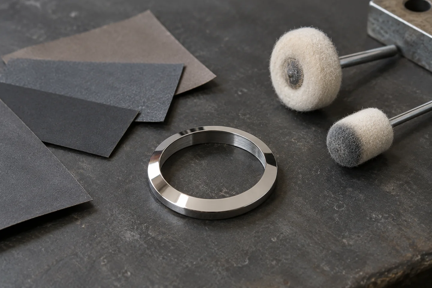
연마 공정은 ‘더 고운 연마재를 차례로 사용한다’는 목록으로 끝나지 않습니다. 단계마다 제거할 결함과 보존할 형상을 정해야 합니다. 깊은 가공흔적을 남긴 채 최종 버핑으로 넘어가면 시간과 압력이 증가하고, 모서리나 얇은 벽이 먼저 손상될 수 있습니다.
- 초기 형상과 깊은 흔적의 정리
소결 후 형상, 가공 여유와 흠집 깊이를 확인합니다. 필요하면 절삭·연삭·래핑 등으로 기준 형상을 먼저 정리합니다. 이 단계에서 최종 에지와 조립면을 무너뜨리지 않도록 지지와 접촉 조건을 설정합니다.
- 중간 단계에서 이전 연마흔적 제거
앞 단계의 흠집이 남아 있는지 확인하고 다음 단계로 진행합니다. 가능한 형상에서는 연마 방향을 바꾸어 잔류 흠집을 식별합니다. 도구와 연마재를 분리하고 단계 사이에 세척하여 조대 입자의 혼입을 줄입니다.
- 최종 미세 요철과 반사 외관 조정
연마재, 도구의 순응성, 압력, 상대 속도, 체류시간과 윤활을 조합합니다. 작은 접촉 면적에 힘이 집중되거나 국부적으로 오래 머물지 않도록 합니다. 새 함몰이나 기복이 나타나면 시간 증가에 앞서 원인을 확인합니다.
- 세정·건조 후의 최종 평가
연마제와 잔류물을 제거한 상태에서 외관과 치수를 확인합니다. 세정 전 광택만으로 판정하지 않습니다. 합격 후에는 포장과 취급 과정에서 접촉흔·먼지·재오염이 생기지 않도록 표면을 보호합니다.
두께와 에지에 배분하는 연마 여유
연마 여유는 부품 전체에 동일하게 더하는 값이 아닙니다. 넓은 평면, 좁은 리브, 볼록한 모서리와 오목한 구석은 도구의 접촉 조건이 다릅니다. 볼록한 에지가 먼저 둥글어지고, 깊은 구석에는 이전 단계 흔적이 남는 상황을 함께 검토합니다.
유광면과 헤어라인면이 인접하면 경계의 위치와 폭도 외관 치수입니다. 경계를 보존할 지그, 공정 순서와 마스킹을 검토하고, 기능 홀·체결면·씰링면은 연마 제거의 영향을 따로 관리합니다. 흠집 제거량이 허용 치수 여유보다 크다면 앞 공정의 표면 상태나 형상을 수정해야 합니다.
연마 시간을 제거량으로 간주하지도 않습니다. 도구 마모, 곡률, 접촉 면적과 압력 분포에 따라 같은 시간에도 제거량이 달라집니다. 기준 위치의 두께·단차·표면 높이 변화를 사용해 실제 제거량을 추적합니다.
접촉 하중과 국부 제거량의 분리
연마 장비의 누르는 힘이 같아도 실제 접촉압력은 같지 않습니다. 도구가 평면에서 볼록한 에지로 이동하거나 연마천이 눌리면서 접촉 면적과 압력 분포가 바뀌기 때문입니다. 명목 평균압력은 접촉 하중을 겉보기 접촉 면적으로 나눈 값으로 이해할 수 있지만, 연마입자가 실제로 받는 국부 하중까지 나타내지는 않습니다.
따라서 에지 손실이 커질 때 전체 하중만 낮추기보다 도구의 순응성, 접촉 폭, 진입·이탈 경로와 국부 체류를 함께 검토합니다. 부드러운 도구는 곡면을 따라가기 쉽지만, 측면까지 감싸며 재료를 제거할 수 있으므로 형상 추종성과 에지 보존을 별도로 확인해야 합니다.
단계별 연마량은 부품 평균보다 중요한 위치별로 관리해야 합니다. 같은 면을 연속 처리한다면 특정 위치의 누적 제거 깊이는 각 단계에서 제거된 깊이의 합이며, 그 합이 해당 위치의 형상 여유 안에 있어야 합니다. 넓은 면에서는 흠집이 남아 있는데 에지의 여유가 먼저 소진된다면, 전체 시간을 늘리는 조건은 적절하지 않습니다.
지지와 접촉 경로를 조정하거나 앞 단계에서 더 균일하게 흔적을 정리하는 편이 합리적입니다. 전후 높이를 비교할 때는 연마로 바뀌지 않는 기준면 또는 재현 가능한 기준 체계를 사용해야 합니다. 변화한 면 전체를 매번 새 기준으로 맞추면 평가하려는 형상 변화 일부가 정렬 과정에 흡수될 수 있습니다.
7. 전해연마·HIP·코팅의 역할과 적용 한계
전해연마: 표면을 용해하는 제거 공정
전해연마는 금속을 양극으로 하여 표면을 전기화학적으로 제거하는 공정입니다. 미세 돌출부의 평활화와 표면 청정도 개선에 활용할 수 있지만, 내부 기공을 채우거나 소결체를 치밀화하는 공정은 아닙니다. 모재의 기공과 개재물, 깊은 흠집은 최종 외관에 영향을 줄 수 있습니다.
기계연마와 조합할 때에는 각 단계의 제거량을 합산합니다. 전류 분포와 지그 접촉, 모서리의 형상 변화, 잔류 전해액의 세정·제거도 검토해야 합니다. 경면 외관, 내식성, 청정도와 치수 보존 중 어떤 요구를 개선할 것인지 먼저 정합니다.
HIP: 폐기공 저감을 위한 선택적 치밀화
열간등방압가압인 HIP는 고온과 압력을 이용해 내부 기공을 줄이는 후처리 후보입니다. 일반적인 비캡슐 HIP에서는 외부와 차단된 폐기공이 주요 대상입니다. 표면에 연결된 기공으로 압력 매질이 들어가면 기공을 줄이는 유효 압력차가 약해지므로, 열린 기공까지 일괄적으로 제거한다고 설명할 수 없습니다.
HIP가 필요한 경우에는 기공 연결성, 합금과 열처리 상태, 형상·치수 변화, 후속 가공 여유와 비용을 함께 검토합니다. 산화물·개재물을 제거하거나 과연마로 손실된 에지를 복원하는 공정으로 보아서는 안 됩니다. 경면 부품이라는 이유만으로 모든 제품에 추가할 필요는 없습니다.
박막 코팅: 모재 외관과 코팅 성능의 분리
경질 박막 코팅은 표면의 마찰·마모 특성 등을 조정하는 수단입니다. 모재의 핀홀과 깊은 함몰을 평탄하게 충전하는 대책으로 가정해서는 안 됩니다. 코팅 전 외관과 청정도를 확보한 후 코팅의 부착과 외관을 다시 확인합니다. 표면 경도와 내마모성의 적용 범위는 금속 외장 DLC 코팅 기술자료와 연결하여 검토할 수 있습니다.
8. 경면 품질의 측정 항목과 합격 기준
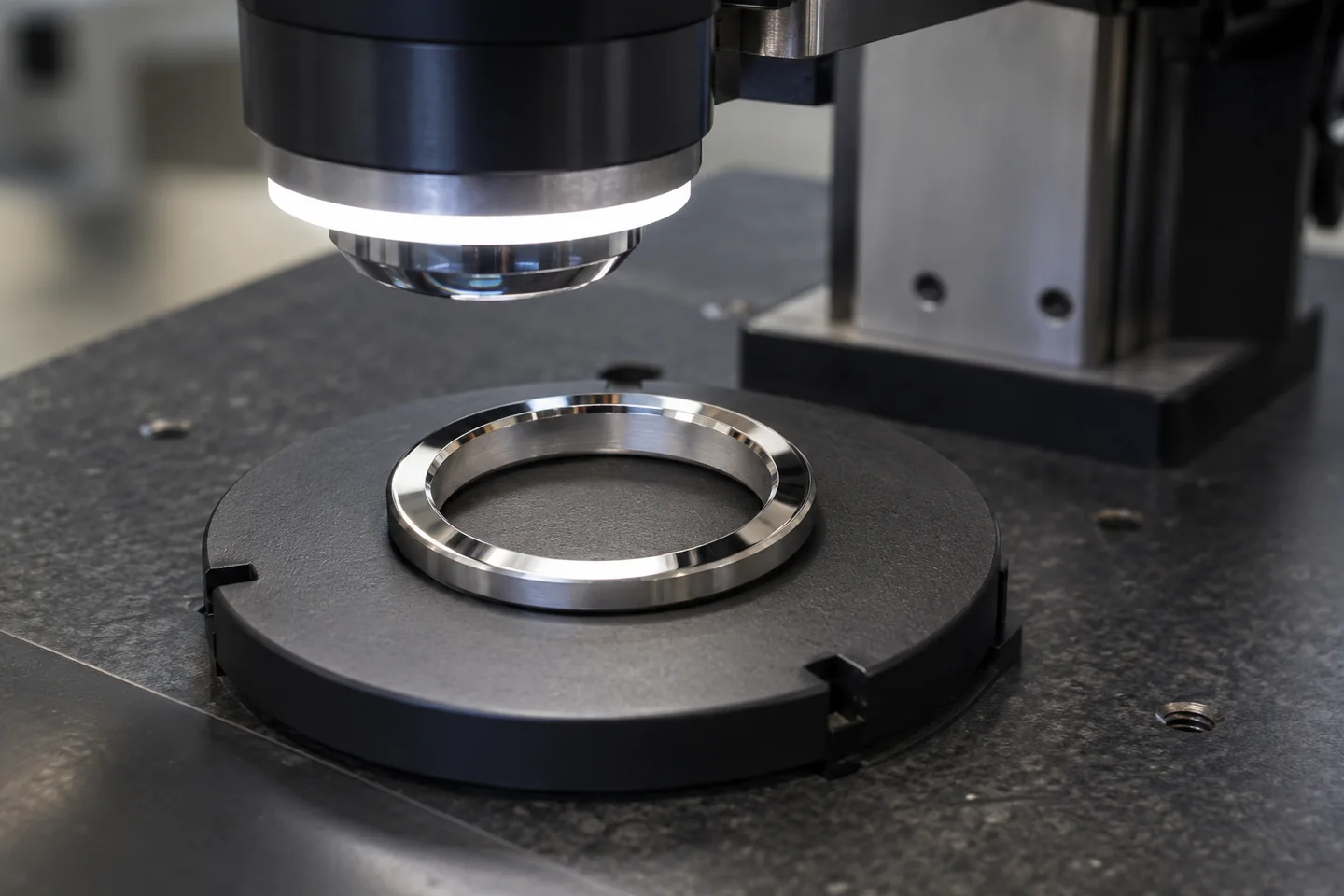
MIM 경면 품질의 평가에서는 평균값과 국부 결함을 분리합니다. Ra는 선을 따라 평가하는 프로파일 파라미터이고, Sa는 면적을 대상으로 하는 파라미터입니다. 둘 다 기준선 또는 기준면에 대한 절대 높이 편차의 평균을 다루므로, 그 값만으로 특정 위치의 최대 함몰이나 점 결함 개수를 제한할 수는 없습니다.

거칠기 수치와 측정 조건의 일치
측정 위치·방향, 평가 길이 또는 면적, 필터, 형상 제거 방식과 장비의 분해능을 맞추어야 결과를 비교할 수 있습니다. 한 줄 측정이 드문 핀홀을 지나지 않을 수도 있고, 측정영역이나 필터에 따라 보고값이 달라질 수도 있습니다. 표면 결함 분석에 필요한 성분을 무심코 제거하지 않도록 평가 목적을 구분합니다.
| 평가 축 | 확인할 내용 | 단독 판정의 한계 |
|---|---|---|
| 전체 밀도 | 측정 방법과 기준 밀도를 고정하고 로트 변화를 확인합니다. | 외관면 가까이 있는 기공의 위치·크기를 직접 알려주지 않습니다. |
| 단면·표면 결함 | 대표 위치의 기공과 함몰 크기·개수·분포를 확인합니다. | 채취 위치, 시편 준비와 영상 분할 조건의 영향을 받습니다. |
| 표면 높이 | Ra·Sa와 목적에 맞는 높이·형상 정보를 확인합니다. | 평균값 하나가 핀홀, 파상도, 광학 외관 전체를 설명하지 않습니다. |
| 광학 외관 | 조명·각도·거리·청정 상태를 정하고 기준 샘플과 비교합니다. | 광택값만으로 헤이즈와 반사상 왜곡을 모두 구분할 수 없습니다. |
| 형상·치수 | 벽 두께, 평면도, 단차, 에지와 기능 치수를 확인합니다. | 치수 합격과 외관 합격은 별도로 확인해야 합니다. |
외관 기준을 문서화하는 방법
외관 중요면의 구역, 허용 결함의 크기와 개수, 군집 여부, 모서리 인접 여부를 도면 또는 외관 규격에 연결합니다. 관찰 조명과 각도, 거리, 확대 관찰의 적용 범위도 지정합니다. 대표 합격품과 경계 샘플을 확보하면 단순히 ‘깨끗한 경면’이라고 표현할 때 생기는 해석 차이를 줄일 수 있습니다.
곡면과 작은 부품에는 측정 장비의 조사 면적과 곡률 적합성을 확인합니다. 평판에서 얻은 광택값을 좁은 곡면에 그대로 적용하지 않습니다. 조도, 광택, 핀홀의 수치 한계를 모든 제품에 공통으로 부여하기보다 사용 환경과 외관 요구에 맞춰 정합니다.
정밀 분석의 선택적 활용
원인 분석이나 공정 검증에 필요한 경우 X선 CT로 내부 기공의 위치와 연결성을 조사할 수 있습니다. 다만 재질, 두께, 해상도와 영상 분할 조건에 따라 검출 한계가 달라집니다. 복셀 크기만으로 검출 가능한 모든 기공 크기를 정할 수 없으며, ‘검출되지 않음’을 ‘기공이 없음’으로 바꾸어 해석하지 않습니다.
모든 양산품에 정밀 단면 분석이나 CT를 적용할 필요는 없습니다. 개발 단계의 원인 검증, 정기적인 공정 확인, 일상 외관 검사로 역할을 나누고 실제 위험과 결함 발생 양상에 맞춰 검사 범위를 설정합니다.
함몰 통계와 측정 영역의 선택
함몰을 정량화할 때는 개수, 단위 관찰면적당 개수, 개구 면적률, 크기 분포와 최대 관찰 크기를 구분합니다. 같은 면적률이어도 작은 함몰이 분산된 표면과 큰 함몰이 집중된 표면은 외관상 다르게 평가될 수 있습니다. 비교 시에는 검사 면적뿐 아니라 검출 하한, 영상 분할과 군집 처리, 관찰 경계에 걸친 결함의 계수 규칙도 고정해야 합니다.
표면에서 측정한 개구 면적률을 내부의 체적 기공률로 바로 바꾸어 해석하지 않습니다. 또한 결함 개수와 불합격 부품 비율은 별도 지표입니다. 후자는 결함의 크기·위치·군집 등에 대해 미리 정한 외관 판정 규칙을 부품별로 적용한 결과입니다.
기공이 없는 작은 구역만 골라 낮은 Sa를 얻으면 금속 기지의 연마 상태는 설명할 수 있지만 부품 전체의 외관 품질을 대표하지 못합니다. 반대로 깊은 함몰이 포함된 평균 거칠기만으로는 주변 기지의 미세 흠집이 개선되었는지 구분하기 어렵습니다. 목적에 따라 대표 외관 구역의 평가와 결함을 제외한 기지 표면 평가를 나누되, 제외 영역과 처리 규칙을 명시하고 원본 높이 데이터를 함께 보관합니다.
함몰을 임의로 삭제하거나 보간해 만든 수치를 무결점 표면의 측정값처럼 제시해서는 안 됩니다. 광학 측정에서 함몰 내부의 데이터가 누락됐다면 그 영역을 자동으로 평탄한 면으로 취급하지 않고, 누락 상태와 장비의 측정 가능 범위를 확인합니다.
추가 연마를 중단해야 하는 조건
연마 단계의 종료 조건은 조도가 더 낮아지는 시점 하나로 정하지 않습니다. 잔류 흠집 감소와 함께 함몰 개수, 반사상 기복, 에지 손실과 잔여 치수 여유를 동시에 추적합니다. 흠집은 줄지만 새로운 함몰과 에지 손실이 증가한다면, 계속 연마하기보다 도구 조건 또는 앞 공정으로 판단을 되돌려야 합니다.
개발 중의 중단 기준과 최종 제품의 합격 기준은 구분하되, 최종 조건은 외관·형상·기능 치수를 모두 만족해야 합니다. 경계 부근의 측정값이나 판정이 반복 관찰에서 흔들리면 측정·관찰 조건을 먼저 확인하고, 그 변동보다 작은 차이를 공정 개선 효과로 단정하지 않습니다.
9. 소결과 연마를 연결하는 양산 개발 순서
경면 사양은 소결품을 완성한 뒤 연마 업체에 전달하는 마지막 요구사항으로 남겨두기 어렵습니다. 중요 외관면, 최종 두께와 경계 형상, 예상 연마 여유를 제품 설계 단계에서 함께 정해야 합니다. 제조 경로는 MIM 공정과 필요한 정밀 후가공·표면처리를 연결하여 구성합니다.
- 외관 요구와 형상 여유의 확정
경면·무광 구역, 조립면, 에지, 지그 접촉 허용 위치를 지정합니다. 기준 샘플과 검사 조건을 정하고, 제거 가능한 재료량을 기능 치수와 연결합니다.
- 소결 상태와 최종 연마면의 대응
평균 밀도뿐 아니라 중요 외관면 근처의 대표 단면을 확인합니다. 성형 캐비티와 소결 로트를 구분하고, 실제 연마 후 나타나는 결함 위치와 비교합니다.
- 단계별 제거량과 결함의 추적
같은 기준 위치에서 연마 전·중간·최종 상태를 비교합니다. 흠집은 줄고 핀홀은 늘어나는지, 도구나 압력 변경으로 새로운 기복이 생기는지 확인합니다.
- 공정 조건과 합격 범위의 고정
피드스톡·성형·탈지·소결 조건과 연마 도구·소모품·세정 조건을 연결하여 관리합니다. 소재나 공정이 바뀌면 기존 외관 승인 범위가 유지되는지 다시 검증합니다.
미세 기공에 대한 대책은 결함 위치와 원인에 따라 달라집니다. 특정 로트나 외관면에 집중된다면 앞 공정의 균일성을 조사하고, 연마 단계 변경 이후 증가한다면 도구·압력·오염과 제거량을 함께 확인합니다. 추가 연마로 해결할 수 있는 흠집과 소결 상태를 바꿔야 하는 잔류기공을 구분하는 것이 공정 선택의 출발점입니다.
동일 시간과 동일 제거 깊이의 비교
공정 변경의 효과는 상대밀도가 높아졌다는 결과 하나로 종료하지 않습니다. 조건을 바꾼 시편에서 동일 외관 구역의 최종 제거량을 맞춘 뒤 기공 노출, 반사상, 에지와 조립 치수를 함께 비교해야 합니다. 소결 상태가 개선되어도 변형 보정을 위해 더 많은 재료를 제거한다면 기존과 다른 깊이의 기공이 노출될 수 있습니다.
반대로 연마량을 줄여 핀홀 수가 감소했더라도 이전 단계의 깊은 흔적이 남아 있을 수 있습니다. 이러한 상호작용을 분리해야 소결 개선과 연마 조건 변경의 기여를 정확히 판단할 수 있습니다.
단계별 비교에서는 부품의 기준 형상으로 관찰 구역을 등록하고, 누적 제거량과 함께 표면 영상을 보관합니다. 여기서 ‘같은 위치’는 같은 평면 좌표나 형상 구역이라는 의미이며, 연마 이후에도 같은 재료 깊이를 보고 있다는 뜻은 아닙니다. 함몰의 개수가 늘었을 때에는 새 제거면에서 기공이 노출된 영향과 도구가 만든 탈락을 모두 검토해야 합니다.
이를 구분하려면 같은 소재 상태에서 서로 다른 도구 조건을 비교하고, 가능하면 공통 제거 깊이에 도달한 표면끼리 추가 비교합니다. 같은 시간만 비교한 결과에는 제거 속도 차이와 노출 깊이 차이가 동시에 포함됩니다.
도구·하중의 상호작용을 확인하는 개발 실험
개발 실험은 ‘도구를 바꾼 뒤 좋아졌다’는 전후 비교보다 조건 간 상호작용을 확인할 수 있도록 구성합니다. 예를 들어 도구의 순응성과 접촉 하중을 서로 교차하여 조합하고, 각 조합에서 실제 제거량·잔류 흠집·함몰·에지 변화를 함께 측정할 수 있습니다. 낮은 하중의 효과가 특정 도구에서만 나타난다면 하중 단독의 효과로 일반화하지 않습니다.
동일 시간의 제거 효율을 비교하는 실험과, 공통 제거 깊이에서 표면 손상을 비교하는 실험은 목적이 다르므로 결과도 구분합니다. 비교 범위는 설비와 부품에서 사전 확인한 허용 범위 안에서 정하며, 조도 최솟값 하나만으로 조건을 선정하지 않습니다.
소결 로트와 연마 효과를 분리하는 반복 검증
도구 조건마다 다른 소결 로트를 배정하면 소재 편차와 연마 효과를 분리하기 어렵습니다. 각 비교 조건이 같은 로트 안에 포함되도록 배치하고, 필요하면 로트나 작업 일자를 묶어 분석하는 블록 설계를 사용합니다. 블록 안에서는 가능한 범위에서 처리 순서를 무작위화하고 도구 마모·세정·컨디셔닝 상태를 기록합니다.
같은 부품의 여러 시야는 그 부품 안의 분포를 보여주는 측정이며, 별도 부품에 같은 연마 조건을 다시 적용한 공정 반복과는 다릅니다. 부품 간 편차를 평가하려면 실제 공정이 독립적으로 반복된 단위가 필요하며, 여러 부품을 한 번에 처리하는 설비에서는 처리 배치도 구분해야 합니다.
| 비교 목적 | 유지하거나 기록할 조건 | 함께 보는 결과 | 해석할 때의 주의점 |
|---|---|---|---|
| 같은 시간의 제거 효율 | 시작 표면·소재·도구 상태와 실제 처리시간을 기록합니다. | 제거량, 형상 변화, 흠집과 함몰을 확인합니다. | 더 깊게 제거된 면의 함몰 증가를 도구 손상만으로 해석하지 않습니다. |
| 같은 제거 깊이의 표면 | 공통 깊이에 도달했는지 확인하고 필요한 시간과 도구 조건을 기록합니다. | 함몰, 기지 거칠기와 에지 보존을 비교합니다. | 소재의 국부 편차가 사라진다고 가정하지 않습니다. |
| 양산 반복성 | 로트·처리 배치·작업 순서·소모품 상태를 구분합니다. | 부품별 외관·치수 합격 여부와 분포를 확인합니다. | 한 부품의 여러 시야를 독립된 여러 부품으로 세지 않습니다. |
안정적인 MIM 경면 품질은 치밀한 소재, 보존된 형상, 관리된 제거량과 일관된 외관 판정이 함께 확보될 때 가능합니다. 시제품 한 개의 높은 광택보다, 최종 치수를 유지하면서 같은 외관 상태를 반복해서 만들 수 있는 공정 범위를 검증하는 것이 양산 개발의 목표입니다.
English edition
MIM mirror finish: residual porosity, sintering and polishing of metal housings
A mirror finish on a metal injection moulded component is established across the manufacturing chain. Final buffing reduces fine surface irregularities, but material removal can also expose subsurface pores or alter edges and functional dimensions. The condition of the material at the eventual finished surface must therefore be considered together with the polishing allowance.
Watch bezels, wearable frames and metal heads for beauty devices are particularly sensitive to reflected light. A small depression that is inconspicuous on a matte surface may become a visible dark point after polishing. This does not, by itself, establish that polishing created a new pore. Existing porosity, particle pull-out, removal of a smeared surface layer and polishing residue require different corrective actions.
Surface finish is more than average roughness
Overall form, waviness, fine roughness and isolated defects describe different aspects of a surface. Form and longer-wavelength irregularities can distort reflected lines. Fine texture affects scattering, while an isolated pinhole can remain unacceptable despite a low average roughness value. A curved part also changes reflected images through its intended geometry; this must be distinguished from unwanted local waviness.
A drawing that specifies only “mirror polish” or a roughness limit leaves important requirements undefined. Cosmetic zones, viewing conditions, allowable local defects, protected edges and functional mating surfaces should be specified together. Gloss, image clarity and dimensional conformity are related but separate requirements.
How polishing exposes subsurface pores
MIM combines metal powder and binder into a feedstock, moulds the required shape, removes the binder and densifies the metal skeleton by sintering. Residual porosity depends on powder packing, moulding uniformity, debinding and the sintering history. The appearance of the as-sintered surface cannot reveal every pore at a greater depth.
A closed pore becomes surface-connected when the removal plane intersects it. For a spherical pore of radius r, centre depth z and material removal depth t, the opening radius is a = √[r² − (z − t)²] when |z − t| < r. This is a geometric explanation, not a model for predicting production acceptance. Real pores are irregular and may be connected; plastic flow and particle pull-out further affect the observed surface.
The opening can increase as the polishing plane approaches the pore centre and decrease after it passes the centre. Sufficient removal may eliminate that particular pore, but another pore may be exposed at a greater depth. Additional removal also consumes thickness and dimensional allowance. Neither continuously improving appearance with polishing time nor a universally denser surface skin should be assumed.
Why equal pore volume fractions can give different surface populations
Bulk density reflects the total pore volume but does not directly indicate how that volume is distributed among individual pores. Consider a geometric model containing uniformly distributed, non-overlapping spherical pores of one radius r, neglecting boundary effects. If the pore volume fraction is φ, the pore number per unit volume is NV = 3φ/(4πr³). The expected number intersected per unit area of a plane is NA = 2rNV = 3φ/(2πr²), because pores with centres within one radius on either side intersect that plane.
Thus, many small pores and fewer large pores can produce different section appearances at the same pore volume fraction. A reduction in counted pores alone does not establish improved densification. Count, opening size and area fraction should be evaluated together, with the detection limit of the observation method specified. Small pores below that limit will not appear in the recorded population.
Actual MIM parts exhibit pore-size distributions, clusters, connected paths and local density gradients. The model is not a production pinhole-yield equation. It explains why bulk density, section pore count and the largest defect size provide different information.
Sections, connectivity and final surface depth
A round pore section does not prove that the void is isolated from the external surface. Features that appear as separate dots in one section may connect through narrow passages at another depth. An elongated depression also requires differentiation from a section through a pore network or an inclusion pull-out site.
Investigations should record size distribution, elongation, clustering and distance from the surface alongside area fraction. Where connectivity determines the treatment route, additional sections or three-dimensional analysis with suitable resolution provide further evidence.
Cosmetic development benefits from examining the depth range in which the final surface may lie, rather than only the as-sintered surface. Combined mechanical and electrochemical removal, together with local removal variation, can place different regions at different depths. Incremental removal on representative development specimens can track opening size and distribution in the same cosmetic zones. Relating destructive sections to finished-part appearance nevertheless requires a common location reference and a record of removal depth.
Powder and feedstock selection
Finer powder offers greater specific surface area and can increase the driving force for sintering. However, oxygen content, agglomeration, binder demand and feedstock rheology also change. Studies of MIM 316L show that particle-size effects depend on composition and sintering atmosphere. The smallest average particle size is not automatically the best choice for every process.
Particle-size distribution, shape, agglomeration, contamination, oxygen and carbon should be reviewed together. Gas and water atomization describe production routes; neither label alone establishes suitability for a cosmetic finish. Even powders carrying the same alloy designation can respond differently because of powder condition and composition.
The powder volume fraction must remain compatible with uniform filling and controlled debinding. Increasing the solids loading without confirming processability is not a reliable route to improved finish. Powder–binder separation or uneven filling can lead to local differences in green density, shrinkage and residual porosity. Gate regions, flow ends, junctions and thickness transitions are possible investigation locations, but their significance must be verified for the actual geometry.
Tracing location and manufacturing history
Defects should be grouped by both their location within the part and their manufacturing history before they are combined into a batch average. Recurrence in the same region of one cavity provides a reason to investigate filling and local powder concentration. Variation with furnace loading position across several cavities calls for examination of thermal history and atmosphere.
Changes associated with a polishing tool or work zone instead direct attention to removal and contact conditions. These patterns narrow the investigation; none independently proves a root cause.
Debinding, sintering and local densification
Interconnected voids during debinding provide routes for binder removal and decomposition products. They should not be evaluated as if they were the residual porosity of a finished sintered component. The objective is to remove the binder while retaining a stable metal skeleton, then achieve the required densification during sintering.
Inappropriate removal conditions can produce cracks, swelling or residue. Binder systems and local wall thickness require corresponding process schedules. A temperature or hold time established for one solvent, catalytic or thermal debinding route cannot simply be transferred to another.
Sintering develops particle bonds and changes pore size, shape and connectivity. Connected pores may become isolated as densification progresses. Higher temperatures or longer holds must nevertheless be balanced against grain growth, distortion and trapped gas. Atmosphere selection is also connected to oxide reduction, moisture, oxygen, residual carbon and alloy chemistry. Conditions reported for one feedstock are not universal production settings.
316L and 17-4PH require separate consideration. Their austenitic and precipitation-hardening metallurgical systems, hardness and heat-treatment routes affect subsequent finishing. Mechanical properties, corrosion requirements and appearance must be considered together when setting the sequence.
Relative density compares a measured density with an appropriate reference density. Composition and material state matter, as does liquid ingress into surface-connected pores during measurement. Equal bulk densities do not guarantee equal pore size distributions or equal conditions immediately below the cosmetic surface. Bulk density is useful for process monitoring, while local surface integrity requires a separate assessment.
Oxides, residual carbon and the near-surface region
Oxygen affects more than pore volume. A comparative MIM 316L study observed oxide particles involving silicon and manganese, with consequences for densification and the distribution of alloying elements. Treating every dark feature in a section as an empty void can therefore confuse porosity with non-metallic inclusions. Distinguishing retained oxide particles, actual depressions and particle pull-out sites changes the basis for deciding whether to modify feedstock cleanliness, the sintering atmosphere or polishing conditions.
Debinding cannot be described fully by shape retention or mass loss alone. Residual carbon also affects phase formation and shrinkage during subsequent sintering. Research on injection-moulded 17-4PH related different residual-carbon levels to high-temperature δ-ferrite formation and density gradients across the section.
If the same peak temperature and hold time give different densification patterns, the preceding debinding history and residual carbon warrant investigation. Phases present during sintering must be distinguished from the final microstructure after cooling and heat treatment.
Carbon and oxygen are not independent variables that should simply be minimized without considering their interaction. In some 316L powder systems, carbon participates in oxygen removal, while excessive residual carbon can impair final composition, microstructure and corrosion performance. Changes in powder oxygen and binder-derived carbon can alter the result of an otherwise unchanged thermal schedule.
Development should therefore relate incoming powder data, the debound condition and final sintered chemistry. Carbon additions reported for one study are not transferable recipes for another feedstock.
For a uniform matrix composition, the overall pore-volume fraction is the volume-weighted average of the local fractions. A thin near-surface region may contribute little to the measured bulk density even when its local porosity increases. If that region becomes the polished cosmetic surface, its effect on appearance can be substantial. Stable bulk density accompanied by increasing pinholes in one cosmetic zone therefore calls for comparison of that zone’s sections and removal history, rather than repeated bulk measurements alone.
Distinguishing pore exposure from polishing defects
A small depression may be an exposed pore, a particle pull-out site or another local defect. Directional lines suggest scratches that may originate from a previous stage, coarse abrasive contamination or detached particles. Broad irregular texture can arise from over-polishing, selective removal and material–tool interactions. Haze and staining may involve residues, cleaning, drying or chemical changes.
Observation after cleaning and at the same location after successive finishing stages helps distinguish these mechanisms. A representative cross-section can provide further evidence. Metallographic preparation must itself be controlled: grinding can smear metal over pores, while unsuitable preparation can pull particles out and create apparent voids. Dark regions should not automatically be treated as true porosity in image analysis.
SEM and compositional analysis of remaining particles may assist an investigation. Neither a single image nor analysis of an empty depression can fully reconstruct its formation history. They are most useful alongside manufacturing records and before-and-after comparisons.
Designing the polishing sequence
Each stage should have a defined removal objective and a defined shape to preserve. Initial machining, grinding or lapping can establish the required form and remove deeper marks. Intermediate stages remove preceding abrasive damage. Final polishing adjusts fine texture and optical appearance. Skipping an effective intermediate stage can lead to excessive pressure and dwell time during buffing.
Where geometry permits, changing polishing direction can help reveal scratches left by a previous stage. Tools and abrasives should be separated, with cleaning between stages to reduce coarse-particle carryover. Pressure, relative speed, dwell time, lubrication and tool compliance must be treated as a combined process rather than independent settings.
Removal is not uniform across flats, convex edges, narrow ribs and recesses. Convex edges may round before deeper marks disappear from a recess. Boundaries between polished and brushed zones also require positional control. Fixtures, masking and process order should protect functional holes, sealing surfaces, mating faces and appearance boundaries.
Polishing time is not a direct measure of material removal. Tool wear, curvature, contact area and pressure distribution change the removal rate. Thickness, step height or surface-height measurements at defined locations provide more useful evidence. If the material required to remove a defect exceeds the available dimensional allowance, the upstream surface or part design must be revised.
Final evaluation follows cleaning and drying. Residual compounds must not obscure defects or create a misleading appearance. Handling and packaging then protect the accepted surface from contact marks and contamination.
Applied force and local removal allowance
Equal applied polishing forces do not necessarily produce equal contact pressures. Contact area and pressure distribution change as a tool moves from a flat region to a convex edge or as its pad deforms. Nominal average pressure can be understood as applied force divided by apparent contact area, but this does not describe the local load carried by individual abrasive particles.
When edge loss increases, tool compliance, contact width, entry and exit paths, and local dwell should therefore be reviewed alongside total force. A compliant tool can follow curved surfaces, but it may also wrap around an edge and remove material from the side. Shape following and edge preservation require separate verification.
Removal allowance should be managed at critical locations rather than only as a part average. For sequential processing of the same surface, cumulative removal at a particular location is the sum of the local removal depths from the individual stages. This total must remain within the geometrical allowance at that location.
If the edge allowance is exhausted while scratches remain on a broader surface, extending the overall process time is inappropriate. Adjusting support and tool paths or obtaining more uniform scratch removal in an earlier stage is a more useful response. Before-and-after height comparisons should use an unaffected reference surface or a reproducible datum system. Re-aligning each measurement solely to the changed surface can absorb part of the geometrical change being evaluated.
Electropolishing, HIP and coatings
Electropolishing removes metal by anodic dissolution. It can improve microtopography and surface cleanliness, but it does not fill pores or densify the bulk material. Substrate pores, inclusions and deep scratches may affect the final result. Combined mechanical and electrochemical removal must remain within the dimensional allowance. Current distribution, rack contact, edge changes and removal of electrolyte residues require control.
Hot isostatic pressing is an optional densification treatment for suitable parts. Conventional capsule-free HIP mainly addresses pores isolated from the external pressure medium. When pores remain connected to the surface, the medium can penetrate them and reduce the effective pressure differential. Complete removal of all surface-connected defects cannot be assumed.
HIP selection requires evaluation of pore connectivity, alloy and heat-treatment state, dimensional response, subsequent machining and cost. It does not generally restore edges already lost through polishing or provide a universal remedy for inclusions and oxides. It is not a mandatory step for every mirror-finished MIM component.
Hard thin-film coatings can modify tribological properties, but they should not be specified as a general method for filling substrate pinholes or levelling deep depressions. Substrate appearance and cleanliness are established first, followed by coating adhesion and appearance verification.
Measurement and acceptance
Ra is the arithmetic mean of absolute profile-height deviations; Sa is the corresponding areal parameter. Neither average, on its own, controls the maximum size, number or location of isolated depressions. Measurement direction and location, evaluation length or area, filtering, form removal and instrument resolution should be specified for meaningful comparisons. A single trace may miss a sparse pinhole.
Bulk density, local pore observations, surface-height measurements, optical appearance and dimensions serve different purposes. Cosmetic requirements should define the inspected zones, allowable defect size and count, clustering and proximity to edges. Viewing illumination, angle, distance and the role of magnification should also be agreed. Approved and boundary samples reduce ambiguity.
Gloss alone cannot characterize haze or reflected-image distortion. Small or curved parts require an instrument footprint and geometry appropriate to their surface. A measurement taken on a flat coupon cannot be transferred uncritically to a narrow curved feature.
X-ray CT can help investigate internal pore location and connectivity where justified. Detectability depends on material, thickness, resolution and segmentation. Voxel size is not a universal minimum detectable pore size, and “not detected under the specified conditions” does not prove absence of porosity. Development analysis, periodic process verification and routine production inspection should have distinct roles.
Defect statistics and measurement selection
Quantify depressions using distinct measures: total count, count per inspected area, opening area fraction, size distribution and the largest observed size. Equal area fractions can describe either dispersed small depressions or a concentration of larger ones, with different appearance consequences. Comparisons require consistent inspected areas, detection thresholds, segmentation and cluster rules, and conventions for defects intersecting the observation boundary.
Surface opening area fraction should not be directly treated as internal volumetric porosity. Defect count and the fraction of rejected parts are also different measures. The latter results from applying predetermined size, location and clustering acceptance rules to individual parts.
A low Sa obtained by selecting a small pore-free region may describe the polished matrix, but it does not establish the appearance quality of the entire part. Conversely, an average dominated by deep depressions may obscure improvements in the fine scratches of the surrounding matrix. Where needed, evaluate a representative cosmetic region separately from the matrix with defects excluded, while identifying the excluded regions and processing rules and retaining the original height data.
Values obtained by deleting or interpolating depressions must not be presented as measurements of a defect-free surface. Missing optical data inside a depression should not automatically be treated as a flat surface; the missing-data condition and the instrument’s measurement capability require review.
Stop criteria and final acceptance
A polishing stage should not end solely at the point where roughness reaches a lower value. Track remaining scratches together with depression count, reflected-image waviness, edge loss and remaining dimensional allowance. If scratches decrease while new depressions and edge loss increase, reconsider the tooling or upstream process instead of extending polishing.
Development stop criteria and final product acceptance criteria serve different purposes, but the final process must satisfy appearance, geometry and functional dimensions together. If measurements or visual decisions near an acceptance boundary vary on repetition, verify the measurement and observation conditions first. A difference smaller than that variability should not be claimed as demonstrated process improvement.
Developing a repeatable production window
Define cosmetic zones, edges, functional surfaces, permitted fixture-contact areas and material-removal allowance before finalizing the process. Relate bulk and local sintered conditions to the surface that will remain after finishing. Track mould cavity, sintering lot, surface location and polishing stage so that local defects can be linked to the relevant conditions.
Compare the same reference locations before polishing, after intermediate stages and after final cleaning. Determine whether scratches decrease while pinholes increase, or whether new waviness appears after a tool or parameter change. Lock the validated feedstock, moulding, debinding, sintering, polishing and cleaning conditions together, and reassess appearance when those conditions change.
Comparing equal time with equal removal depth
An increase in relative density is not, by itself, a complete validation of a process change. Compare pore exposure, reflected-image quality, edges and functional dimensions after matching final removal depth in the same cosmetic zones. Improved sintering may still require more corrective removal if distortion changes, exposing a different subsurface region.
Conversely, reducing removal may lower the pinhole count while leaving deeper marks from an earlier operation. Separating these interactions makes it possible to assess the contributions of densification and polishing changes more reliably.
Register inspection regions to the part geometry and retain surface images together with cumulative removal measurements. The same location means the same lateral coordinates or geometrical region; it does not mean that the same material depth remains visible after polishing. An increased depression count may reflect exposure of deeper pores, tool-induced pull-out, or both.
Comparisons between tool conditions should therefore use comparable starting material and, where practical, include observations at a common removal depth. A comparison made only at equal processing times combines differences in removal rate with differences in the depth exposed.
Interactions, blocks and independent replication
Development trials should reveal interactions rather than rely only on a before-and-after statement that a different tool improved the result. Tool compliance and applied force can, for example, be crossed in a set of combinations, with actual removal, remaining scratches, depressions and edge change measured for each combination. If a lower force helps only with one tool, the result should not be generalized as a force effect alone.
An equal-time test of removal efficiency and a test of surface damage at a common removal depth answer different questions. Their results should be distinguished. Experimental ranges must remain within previously established machine and part limits, and the lowest roughness value alone should not determine the selected condition.
Assigning a different sintering lot to each tool condition confounds material variation with the polishing effect. Include the compared conditions within the same lot and, where appropriate, use lots or working days as blocks in the analysis. Randomize treatment order within each block where feasible and record tool wear, cleaning and conditioning.
Multiple fields on one part describe within-part variation; they are not equivalent to repeating the polishing treatment on separate parts. Evaluating part-to-part variation requires independently treated experimental units. Where multiple parts are processed together, the processing batch should also be identified.
The production objective is a repeatable cosmetic surface that retains its required dimensions. High gloss on one sample is insufficient. Stable mirror finishing requires suitable densification, preserved geometry, controlled removal and consistent acceptance conditions across the complete manufacturing route.
추가 정보
주제 요약
MIM 금속 외장의 경면 품질은 소결체의 국부 기공 상태, 최종 표면의 위치, 연마 제거량과 형상 보존을 함께 검토하여 설계합니다. 연마 후 함몰을 기존 기공·입자 탈락·스미어·잔류물로 구분하고, 거칠기·반사 외관·치수를 별도로 평가합니다.
핵심 포인트
- 평균 밀도와 낮은 거칠기만으로 핀홀이 없는 경면을 보장할 수 없습니다.
- 표면 아래 기공은 연마 제거면과 교차할 때 새로 드러날 수 있습니다.
- 미세 분말, 높은 소결 온도, 긴 연마시간을 각각 독립적인 해결책으로 사용할 수 없습니다.
- 전해연마는 제거 공정이며, HIP는 기공 연결성과 합금 조건에 맞춰 선택합니다.
- 최종 외관 기준에는 결함 분포, 관찰 조건, 에지와 조립 치수를 포함합니다.
자주 묻는 질문
MIM 부품은 경면 마감이 가능합니까?
적절한 소재·소결 상태와 후처리 조건을 확보하면 경면 마감을 검토할 수 있습니다. 다만 형상, 국부 기공, 외관 기준과 연마 여유를 확인해야 하며 합금명이나 평균 밀도만으로 가능 여부를 확정하지 않습니다.
연마를 반복하면 핀홀이 없어집니까?
개별 기공을 지나도록 제거하면 해당 기공은 사라질 수 있습니다. 그러나 더 깊은 기공이 노출될 수 있고, 두께와 에지가 손실될 수 있으므로 허용 제거량과 원인 분석이 먼저입니다.
기공과 연마 중 입자 탈락은 어떻게 구분합니까?
세정 전후와 연마 단계별 동일 위치를 비교하고 필요하면 대표 단면과 잔류 입자를 조사합니다. 외관 영상 한 장만으로 확정하지 않으며 시편 준비 중 발생한 인공물도 확인합니다.
경면 사양 검토에 어떤 정보가 필요합니까?
도면·재질·열처리 상태, 외관 중요면, 목표 마감의 기준 샘플, 기능 치수, 생산 수량과 예상 후처리 순서가 필요합니다. 지그 접촉 흔적의 허용 위치와 포장 요구도 함께 정리하면 공정 검토에 도움이 됩니다.
관련 기술자료
관련 태그

Related posts
미용기기 교체형 금속 헤드: 베요넷 잠금 구조의 가공과 조립

이어폰 충전케이스 힌지: 플라스틱 내부 장착과 MIM 정밀부품 설계

미용기기 MIM 선택 코팅: 외관면·전기 접점·조립면의 정밀 설계
미용기기 MIM 헤드: 접촉 곡면·모서리·조립 단차의 정밀 제조