
시계케이스 초정밀주조: 미세홀·주입 구조·후가공을 연결하는 제조 설계
시계케이스 초정밀주조: 미세홀·주입 구조·후가공을 연결하는 제조 설계
시계케이스의 정밀도는 완성된 외형만으로 결정되지 않습니다. 작은 측면 홀을 남기는 주형 구조, 얇은 몸체까지 용탕을 전달하는 경로, 응고 후 수축과 전면 개방부의 가공 기준이 서로 맞아야 합니다. 시계케이스 초정밀주조는 왁스 패턴에서 필요한 형상을 구체화하고, 세라믹 주형과 주입 구조를 거쳐 조립에 중요한 면을 후가공으로 완성하는 제조 설계입니다.
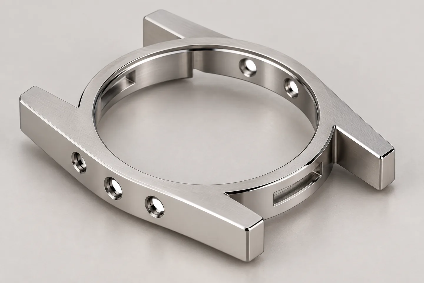
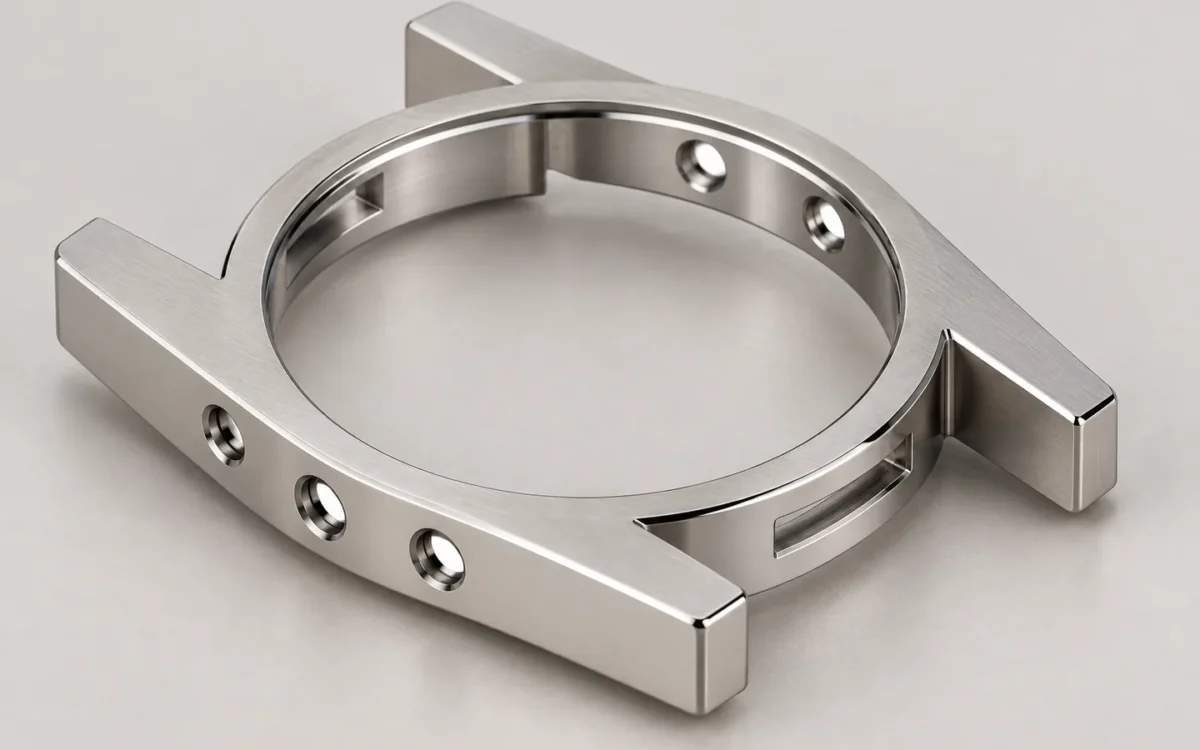
원형 몸체와 양쪽 직선 측벽, 측면 관통홀, 곡면의 슬롯은 하나의 케이스 안에 공존합니다. 이 가운데 주조로 충분히 형성할 수 있는 부분과 최종 절삭이 필요한 부분을 구분하면 재료 제거량과 공정 구성을 함께 검토할 수 있습니다. 핵심은 주조품을 완성품에 가깝게 만들면서, 필요한 가공여유와 검사 기준을 남기는 것입니다.
1. 시계케이스 초정밀주조의 형상 설계: 전면막에서 개방 케이스까지
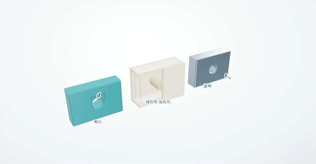
로스트왁스 기반 정밀주조에서는 금속 제품과 대응하는 왁스 패턴을 먼저 만듭니다. 패턴을 세라믹으로 감싼 뒤 왁스를 제거하면 금속이 들어갈 빈 공간이 남습니다. 따라서 완성 금속의 형상은 왁스, 세라믹, 용탕의 순서로 전달됩니다. 금속 분말을 성형한 뒤 탈지·소결하는 MIM과는 재료 이동과 치수 변화의 경로가 다릅니다.
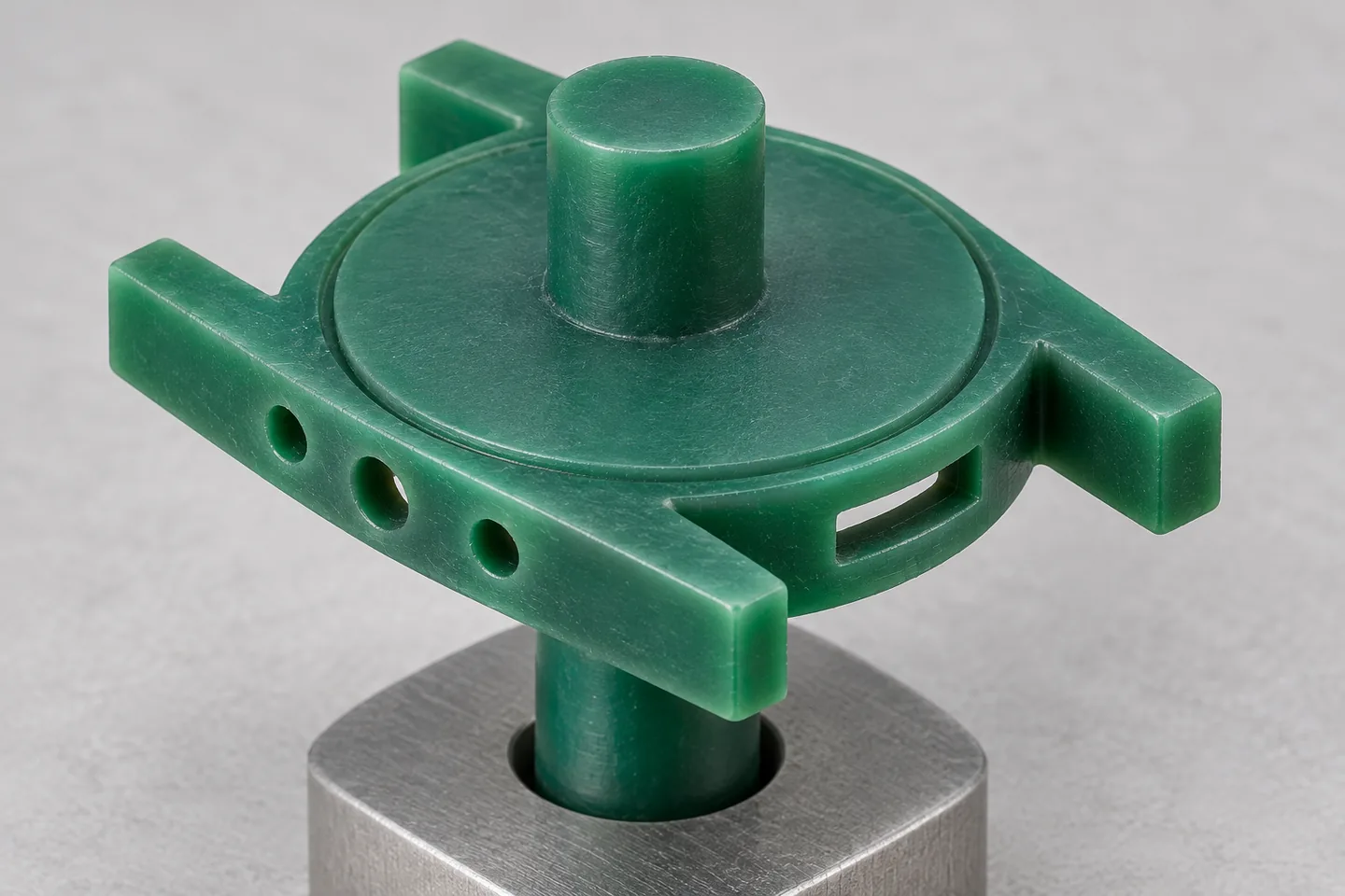
이 제조 구조에서 주목할 부분은 케이스의 중앙 전면입니다. 완성품에서는 유리나 디스플레이가 들어가는 개방부이지만, 패턴과 주물 단계에서는 제거 예정인 전면막을 남길 수 있습니다. 전면막의 중심 부근에 케이스 두께 방향으로 스템을 연결하고, 여러 케이스가 이 스템을 따라 이어지도록 구성합니다.
완성품에 남지 않는 형상도 제조 설계에 포함됩니다
전면막과 스템은 장식이나 최종 조립 부품이 아닙니다. 주조 중에는 패턴과 트리의 연결 및 금속 전달에 참여하고, 이후에는 제거 대상이 됩니다. 따라서 열린 링 형상의 완성품만 보고 곧바로 왁스 금형을 제작하면 실제 주입 경로와 절단·절삭 순서를 충분히 반영하기 어렵습니다.
반대로 전면을 넓게 남기는 설계에도 검토할 조건이 있습니다. 연결부에 금속이 집중되면 주변보다 늦게 냉각되는 구간이 생길 수 있고, 제거량이 늘어나면 후가공 부담이 커집니다. 전면막의 두께, 스템의 연결 위치와 제거 경계는 충전성·응고·가공 접근성을 함께 검토하여 결정합니다.
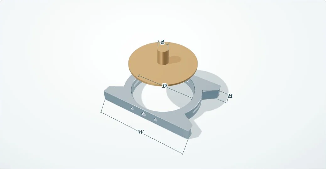
케이스 3D의 D는 제거 후 중앙 개구의 내경, W는 러그를 포함한 전체 폭, H는 스템을 제외한 몸체 높이, d는 중앙 스템의 직경입니다. 형상 전환과 단면의 관계를 보여주기 위한 모델이며, 제작 치수와 허용공차는 실제 제품 도면에서 별도로 정합니다. 관통홀이나 슬롯의 구체적인 기능도 조립 구조가 확정된 뒤 부여합니다.
2. 측면 코어를 사용하는 왁스 금형과 탈형 경로
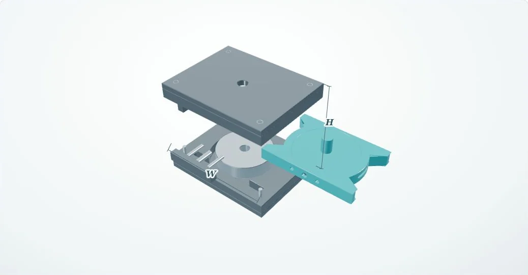
케이스 옆면의 홀과 슬롯은 위아래로만 열리는 금형으로 모두 만들기 어렵습니다. 측면으로 들어간 코어가 왁스 내부의 빈 공간을 형성했다면, 패턴을 꺼내기 전에 그 코어가 빠져나갈 경로가 필요합니다. 금형의 분할은 외관의 파팅라인뿐 아니라 이러한 형상 구속을 기준으로 설계합니다.
두 개의 케이스 캐비티를 배치한 금형에서는 각 캐비티의 측면 코어, 상하 형판, 패턴을 지지하는 부분이 서로 간섭하지 않아야 합니다. 코어가 움직이는 방향은 홀의 축과 연결되며, 금형을 여는 동작은 패턴이 끼이거나 얇은 측벽이 찢어지지 않는 순서로 구성합니다. 코어 수를 늘리는 것만으로 정밀도가 높아지는 것은 아닙니다.
작은 홀을 만드는 코어의 강성과 위치
가늘고 길게 돌출된 코어는 사출 중 압력과 탈형 저항의 영향을 받습니다. 코어의 지지 길이, 선단 형상, 맞춤 위치와 반복 작동 후 유격을 검토해야 하는 이유입니다. 코어가 미세하게 기울어져도 홀 입구는 정상으로 보이면서 안쪽 축선이나 벽 두께가 달라질 수 있습니다.
분할면의 틈은 왁스 플래시로 나타날 수 있습니다. 이 흔적이 패턴에 남으면 주형과 금속으로 이어지므로, 금속 단계에서만 버를 처리하는 방식보다 패턴 검사에서 원인을 확인하는 편이 효율적입니다. 외관이 중요한 면에는 분할 흔적과 게이트 자국의 위치를 미리 정하고, 제거할 때 형상 기준이 훼손되지 않도록 합니다.
금형의 캐비티와 코어는 목표 금속 치수를 그대로 복사한 것이 아닙니다. 왁스의 수축, 셸의 열적 거동, 합금의 응고·냉각과 후가공 여유를 고려한 보정 형상입니다. 이 보정은 시제품 측정으로 확인하며, 홀 중심거리와 개방부 폭처럼 서로 연결된 치수를 함께 평가합니다.
3. 왁스 패턴의 정밀도와 트리 조립 전 형상 유지
왁스 패턴이 부드럽고 쉽게 녹는다는 특성은 제거에는 유리하지만, 형상 유지에는 관리가 필요합니다. 사출 직후부터 냉각, 탈형, 보관, 트리 접합까지 패턴은 온도와 지지 조건의 영향을 받습니다. 얇은 측벽과 길게 뻗은 단부는 부적절한 취급이나 비대칭 냉각으로 변형될 수 있습니다.
사출 조건은 충전 여부만으로 평가하지 않습니다. 금형과 왁스의 온도, 보압과 유지시간, 냉각 상태는 두께가 다른 구역의 수축과 잔류 변형에 영향을 줍니다. 최종 금속에서 발견된 치수 편차를 해결하려면 같은 위치의 왁스 치수를 먼저 확인하여 편차가 시작된 단계를 좁혀야 합니다.
왁스 수정과 금형 보정의 구분
패턴의 작은 흠을 보수할 수 있더라도, 반복해서 같은 위치에 발생하는 형상 편차를 수작업 수정으로만 해결하면 패턴 간 차이가 커질 수 있습니다. 홀 막힘, 분할면 플래시, 측벽의 휨과 접합부 단차를 나누어 보고 금형, 사출, 탈형, 취급 중 어느 단계에서 발생하는지 확인합니다.
트리에 패턴을 붙일 때에는 스템의 중심과 패턴의 자세를 유지해야 합니다. 접합부가 과도하게 두꺼워지거나 패턴이 기울어지면 셸 코팅의 배액과 건조, 주입 후 열 흐름까지 달라질 수 있습니다. 같은 외형의 패턴이라도 트리의 높이와 방향에 따라 다른 환경을 경험하므로 위치를 추적할 수 있는 관리가 유용합니다.
치수 측정은 패턴을 눌러 변형시키지 않는 조건에서 수행합니다. 측정 지지 위치, 온도 상태와 탈형 후 경과시간을 일정하게 해야 수축 변화와 측정 중 변형을 혼동하지 않습니다. 완성품의 합격 여부를 판단하는 검사와, 금형·공정 보정에 쓰는 패턴 측정은 목적을 구분합니다.
수직 스템과 상부 러너를 연결하는 트리 조립
개별 패턴의 위·아래 스템을 중심에 맞추어 연결하면 수직 열이 만들어집니다. 이 열들을 수평 방향으로 배열하고 상부 러너에 접합합니다. 접합면에는 끊김이나 벌어진 틈이 없어야 하며, 국부 가열이 케이스 전면막까지 전달되어 형상을 무너뜨리지 않도록 합니다. 연결부를 매끈하게 정리하는 목적은 외관 개선보다 통로의 연속성과 셸 전사 안정성을 확보하는 데 있습니다.

패턴 사이의 공간은 제품 배치 간격인 동시에 코팅·배액·건조에 필요한 작업 공간입니다. 간격이 좁으면 러그 사이에 슬러리가 고이거나 내화 입자가 걸쳐 쌓일 수 있습니다. 따라서 조립 상태에서 수직 열의 기울기, 스템 접합부와 패턴 간 간섭을 확인하고, 완성된 트리의 방향을 이후 공정까지 연결해 관리합니다.
4. 미세홀의 전사와 세라믹 셸의 기포 제어
설계된 관통홀을 금속에 남기려면 그 공간이 주입 중에도 유지되어야 합니다. 왁스의 홀 안으로 세라믹이 이어지고 충분히 지지된 주형 영역을 형성하면, 왁스를 제거한 뒤에도 그 영역이 금속의 진입을 제한합니다. 금속은 원래 왁스가 차지했던 공간을 채우며, 세라믹을 제거하면 의도한 홀이 드러납니다.
따라서 미세홀 구현은 금형에서 구멍을 뚫는 작업으로 끝나지 않습니다. 좁은 홀 내부의 젖음, 슬러리의 접근과 배액, 건조 상태, 세라믹의 강도와 최종 제거 가능성이 모두 연결됩니다. 긴 홀이나 좁은 슬롯은 입구가 정상으로 보여도 내부에 기포·잔류물이 있거나 충분히 건조되지 않을 수 있습니다.
진공 처리가 작용하는 위치
슬러리 코팅에서 진공을 적용하는 목적은 패턴과 슬러리 사이 또는 슬러리 내부에 포획된 공기를 줄이는 데 있습니다. 점도가 지나치게 높거나 젖음이 부족하면 작은 모서리와 홀 안쪽에서 공기가 빠져나오기 어렵습니다. 침지·회전·배액 자세와 슬러리 상태를 함께 관리해야 미세 형상이 균일하게 전사됩니다.
이 단계의 진공 처리를 용강 자체의 진공 용해나 진공 주조와 같은 의미로 쓰지 않습니다. 또한 코팅 계면의 기포를 줄였다고 금속 내부의 가스 기공과 응고 수축공까지 모두 없어지는 것은 아닙니다. 결함은 발생 위치와 원인이 다르므로 관찰된 형태만으로 한 가지 원인에 연결하지 않습니다.
| 검토 대상 | 발생·형성에 관계하는 요소 | 구분하여 확인할 내용 |
|---|---|---|
| 설계된 관통홀·슬롯 | 금형 코어와 왁스 형상, 세라믹의 연속성과 지지 조건입니다. | 위치·축선·관통 상태와 세라믹 잔류를 확인합니다. |
| 코팅 계면의 기포·젖음 불량 | 슬러리 상태, 표면 청정도, 침지 자세와 공기 배출 경로입니다. | 셸 전사면의 불연속과 위치별 표면 이상을 확인합니다. |
| 금속 내부의 가스 기공 | 용탕의 가스와 청정도, 주입 중 공기 포획 등입니다. | 결함 형태·분포와 용해·주입 조건을 연계하여 검토합니다. |
| 응고 수축공 | 국부 두께와 냉각, 응고 중 급탕 통로의 유지입니다. | 늦게 응고하는 위치와 금속 보충 경로를 확인합니다. |
셸은 미세 형상을 복사하는 표면층과 주입 중 형상을 유지하는 구조를 함께 갖습니다. 두꺼우면 강성이 높아질 수 있지만 열전달과 수축 구속도 달라집니다. 반대로 얇게 만드는 것만으로 정밀도가 개선되지는 않습니다. 셸 두께는 금속 케이스의 벽 두께와 다른 설계 항목이며, 건조·탈왁스·가열 과정의 균열과 박리까지 확인합니다.
초기 코팅 검토에서는 개별 패턴의 홀과 측벽에서 젖음·배액 상태를 확인할 수 있습니다. 다만 트리로 연결하면 패턴 사이의 접근 공간과 배액 방향이 달라지므로, 양산 조건은 실제 트리 상태에서 다시 확인해야 합니다. 한 번의 얇은 초벌 코팅을 주입 강도가 확보된 완성 셸과 동일하게 취급하지 않습니다.
초벌층과 보강층을 연결하는 반복 코팅·건조
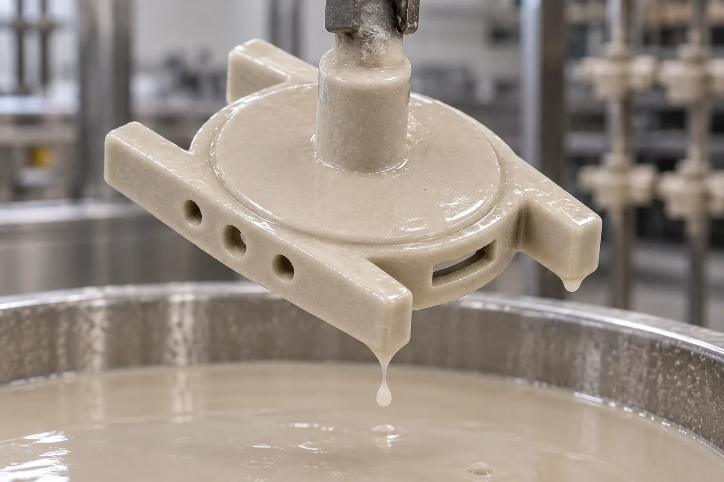
초벌층은 왁스 표면과 직접 맞닿아 금속의 표면 형상을 결정합니다. 이후 층은 이 전사면을 지지하도록 쌓습니다. 슬러리 침지, 배액, 내화 입자 부착, 건조를 반복하되 이전 층이 다음 침지에서 손상되지 않을 상태인지 확인합니다. 한 번에 두껍게 덮으면 필요한 적층 구조 대신 고인 슬러리와 약한 계면이 남을 수 있습니다.
건조는 겉면이 하얗게 변하는 것만으로 판단하지 않습니다. 러그 안쪽과 층 사이의 오목한 구역은 공기 교환이 느릴 수 있습니다. 반대로 초벌층에 강한 바람을 집중하면 표면과 내부의 건조 차이가 커집니다. 온도·습도·기류를 셸 재료와 형상에 맞추고, 외측 과건조와 내측 미건조를 함께 피해야 층 들뜸과 박리를 줄일 수 있습니다.
탈왁스: 빈 공간을 만들면서 셸을 보존하는 단계
탈왁스는 패턴 대부분을 배출해 용탕이 들어갈 공간을 확보하는 과정입니다. 증기 오토클레이브나 전용 가열 방식 등을 선택할 수 있으며, 실제 방식은 왁스와 셸 시스템에 맞춥니다. 어느 방식이든 왁스가 팽창하는 힘과 빠져나가는 경로를 함께 고려합니다. 두꺼운 스템과 얇은 케이스 패턴이 동시에 같은 상태로 녹는다고 가정하지 않습니다.
주입구를 포함한 배출 경로와 주형의 자세가 중요합니다. 제거 후에는 셸 균열, 접합부 손상과 내부 잔류물을 살핍니다. 회수된 왁스의 양만으로 작은 홀 주변의 세라믹 지지부까지 건전하다고 판정하지 않으며, 외형이 유지된 주형도 다음 가열과 취급에서 손상되지 않도록 지지합니다.
소성·잔류물 제거와 주입 전 예열의 역할
탈왁스 뒤의 소성은 남은 패턴 성분을 제거하고 주입에 필요한 셸 상태를 확보하는 단계입니다. 주입 전 예열은 용탕이 얇은 케이스 구역을 채우기 전에 지나치게 냉각되지 않도록 주형의 열 상태를 맞추는 과정입니다. 설비에 따라 이어서 진행할 수 있어도 두 단계의 목적과 판정 항목은 구분합니다.

가열로의 표시 온도만으로 트리 전체의 온도가 균일하다고 판단하지 않습니다. 적재 간격과 유지 조건, 주형 크기 및 꺼낸 뒤 주입까지의 이동시간이 영향을 줍니다. 주형이 식은 정도를 용탕 온도만 높여 보완하면 다른 결함 원인이 될 수 있으므로, 셸과 합금에 맞는 주입 조건을 함께 설정합니다.
5. 다층 트리의 주입 경로와 위치별 품질
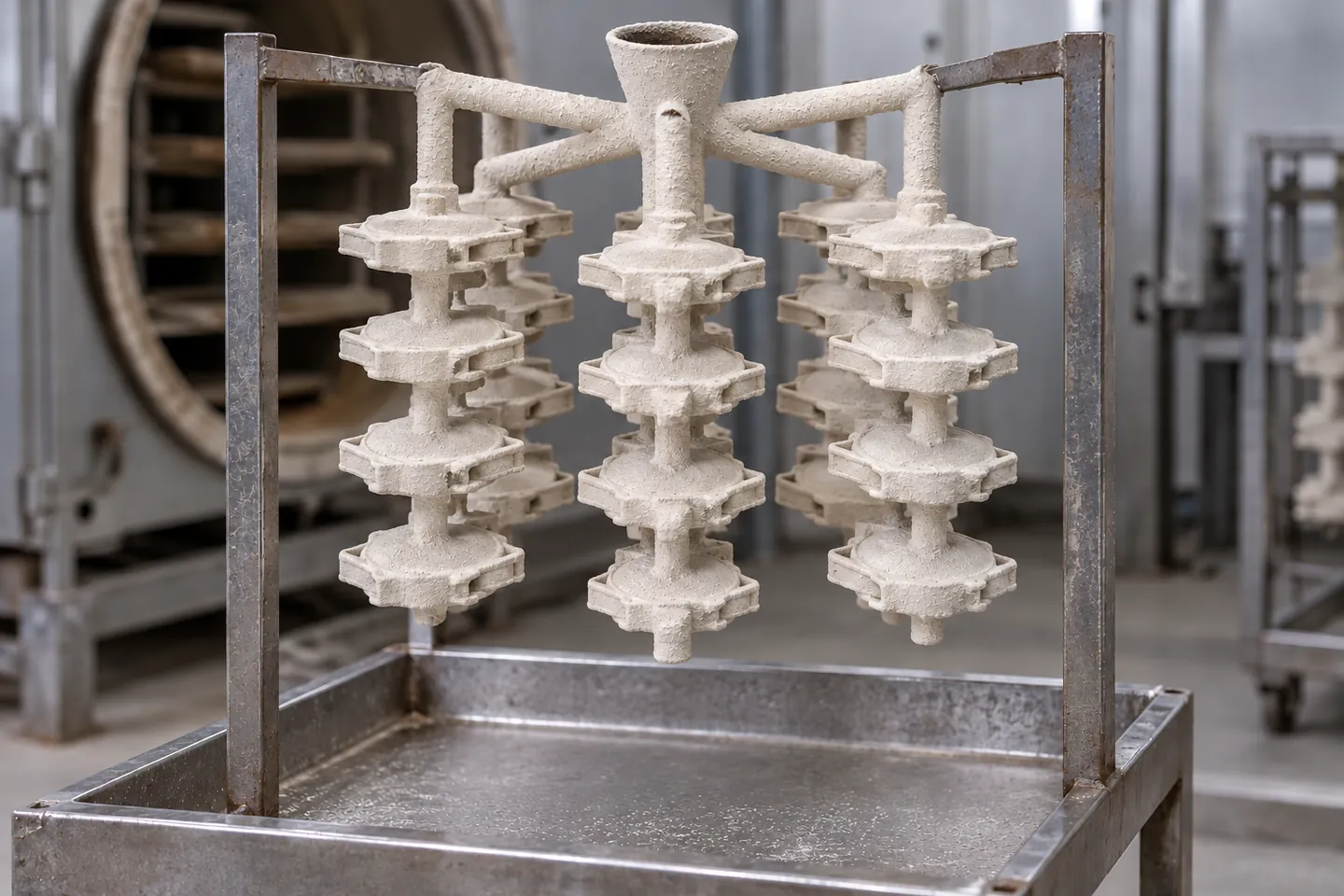
여러 케이스를 한 번에 주조하려면 개별 형상 사이에 금속을 전달할 연결 구조가 필요합니다. 케이스의 원형 면을 수평으로 두고 중심축 방향 스템으로 위아래를 연결하면 수직 열이 형성됩니다. 상부 수평 러너는 각 열의 스템과 이어져 용탕이 들어가는 경로를 만듭니다.
수평 여섯 개를 네 층으로 쌓으면 하나의 트리에 스물네 개의 패턴이 배치됩니다. 이는 배열 구조의 예시이며 생산성이나 합격품 수가 같은 배수로 증가한다는 뜻은 아닙니다. 트리 크기는 코팅·건조 설비, 취급 중 강성, 용탕 공급과 열적 균일성, 후속 분리 작업까지 고려하여 결정합니다.
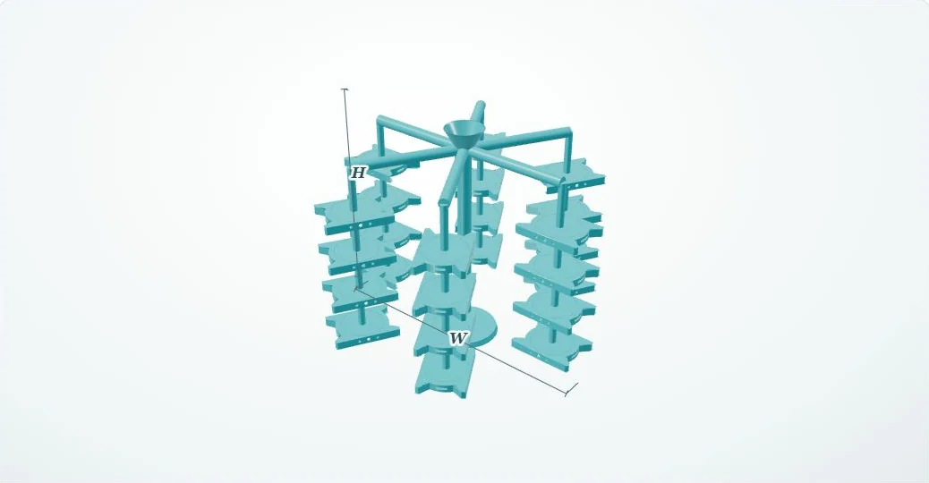
충전 경로와 응고 중 급탕 경로
빈 공간을 채우는 충전과, 금속이 응고하면서 줄어드는 부피를 보충하는 급탕은 연결되지만 서로 다른 문제입니다. 주입 초기에 용탕이 도달했다고 해서 응고 후 내부까지 건전한 주물이 되는 것은 아닙니다. 두꺼운 연결부가 아직 수축하는 동안 그곳으로 향하는 얇은 통로가 먼저 굳으면 보충이 끊길 수 있습니다.
측벽의 얇은 구간, 원형 몸체와 직선부의 접속부, 전면막 중심의 스템 주변은 냉각 조건이 다를 수 있습니다. 상부·하부 패턴 역시 주입 순서와 주변 공간, 셸의 열 상태가 같다고 가정하지 않습니다. 트리의 위치별로 미충전, 표면 이상, 치수와 내부 결함을 비교하면 공정 원인을 찾는 데 도움이 됩니다.
3D의 단계 전환은 연결 통로를 이해하기 위한 표현입니다. 실제 충전 시간이나 응고 순서를 산출한 해석값으로 읽지 않습니다. 생산 설계에서 유동·응고 해석을 사용하는 경우에는 합금 물성, 셸의 열적 특성, 주입 조건과 경계조건을 설정하고 실제 주물 결과로 검증해야 합니다.
주입 직전 상태와 냉각 이력을 연결하는 공정
주입은 용탕을 붓는 순간만의 작업이 아닙니다. 주형 예열 상태, 용탕의 청정도와 온도, 공급량 및 주입의 연속성을 연결해 검토합니다. 통로가 연결되어 있어도 유입 중 공기를 끌어들이거나 산화물이 섞이면 형상 충전과 내부 품질이 서로 다른 결과를 보일 수 있습니다.
주입 후에는 얇은 벽과 두꺼운 연결부의 응고 차이를 고려하여 냉각·취급 조건을 정합니다. 충분히 안정되지 않은 트리를 움직이거나 얇은 케이스를 연결부에서 억지로 꺾지 않습니다. 주형 제거 시점과 방법도 표면 청정도뿐 아니라 케이스의 변형과 손상에 영향을 주는 공정 조건입니다.
6. 수축률 하나 대신 치수별 변화를 추적하는 금형 보정
왁스 금형을 최종 제품보다 크게 만드는 것만으로 모든 치수가 맞아지는 것은 아닙니다. 패턴의 냉각 수축, 셸의 열적 거동, 금속의 응고와 상온 냉각, 주형에 의한 구속이 차례로 작용합니다. 같은 케이스에서도 바깥 폭, 안쪽 개구부, 홀 중심거리와 얇은 벽은 다른 편차를 보일 수 있습니다.
초기 보정량은 공정 이력과 유사 형상에서 출발할 수 있지만, 최종 값은 실제 형상과 재질로 확인합니다. 특정 제작 사례에서 사용한 수축률을 다른 왁스·합금·셸에 그대로 적용하거나 모든 축에 같은 비율로 중복 적용하지 않습니다. 수축률을 계산할 때도 분모가 금형·왁스·금속 중 어느 치수인지 명시해야 합니다.
| 측정 단계 | 같은 위치에서 비교할 항목 | 편차 해석의 목적 |
|---|---|---|
| 금형과 왁스 패턴 | 외형, 측벽 간격, 홀 중심과 전면막 형상을 비교합니다. | 사출·냉각·탈형에서 시작된 차이를 찾습니다. |
| 왁스와 주조품 | 대응하는 치수와 트리 위치별 차이를 확인합니다. | 주형·응고·냉각의 영향과 방향별 보정을 검토합니다. |
| 열처리 전후 | 개구부의 형상과 기준면 관계를 비교합니다. | 열 이력 뒤 남은 변형과 후가공 여유를 확인합니다. |
| 정밀가공·연마 후 | 기능면 치수, 벽 두께와 외관 경계를 확인합니다. | 조립 요구를 만족하는 최종 형상을 판정합니다. |
금형을 보정하기 전에는 측정 기준부터 일치시킵니다. 변형된 외관면을 기준으로 정렬하면 부품 전체가 이동하거나 회전한 것처럼 계산되어 실제 국부 편차가 가려질 수 있습니다. 기능상 기준면과 중심축을 정하고, 어느 영역의 치수를 유지하며 어느 영역의 보정을 허용할지 구분합니다.
7. 오스테나이트계 스테인리스의 조직과 열처리
시계케이스용 스테인리스는 외관 마감과 내식성뿐 아니라 주조 상태의 조직, 가공성 및 기기 내부 부품과의 관계까지 검토합니다. 같은 계열의 재질명이라도 합금 조성, 응고 조건과 후속 열 이력이 다르면 잔류 페라이트와 자기적 반응이 달라질 수 있습니다.
열처리는 필요한 조직과 재료 상태를 확보하는 과정입니다. 선택한 강종과 단면, 현재 조직, 목표 물성에 맞게 검토하며 처리 후 변형도 확인합니다. 특정 온도 범위에 넣었다는 사실만으로 내식성이나 자기적 특성, 형상 안정성을 모두 보장할 수는 없습니다.
산화를 억제하는 분위기에서 열처리하는 경우에도 분위기 관리와 조직 제어의 목적을 나누어 봅니다. 표면 산화가 적다는 사실만으로 목표 조직이나 자기적 특성까지 확보되었다고 판단하지 않습니다. 가열·유지·냉각 조건을 재질 요구와 연결하고, 처리 후 표면 상태와 치수·조직을 함께 확인합니다.
자기적 요구는 실제 기기 조건으로 정합니다
오스테나이트계 스테인리스도 잔류 페라이트 또는 냉간가공으로 생긴 마르텐사이트 때문에 자기적 반응을 보일 수 있습니다. 적절한 용체화 처리는 가공으로 변화한 조직을 조정할 수 있지만, 모든 주조품이 완전한 비자성이 된다는 일반 공식은 아닙니다.
자기 센서 등과의 간섭이 중요한 경우에는 허용 특성과 측정 위치를 정합니다. 자석이 붙는지 여부만으로 정량적인 합격 기준을 대신하지 않으며, 필요에 따라 투자율이나 조직 상태를 확인합니다. 낮은 자기적 반응과 전자파 투과 성능도 같은 항목으로 취급하지 않습니다.
합금에 니켈을 추가로 넣지 않는 공정과 니켈이 없는 재료는 구분해야 합니다. 스테인리스의 원래 조성과 표면 처리, 피부 접촉에 관한 요구는 실제 재질·완성 표면의 사양으로 확인합니다. 재질 이름이나 열처리 명칭만으로 사용 적합성을 확정하지 않습니다.
8. 전면 개방부와 조립 기능면을 완성하는 정밀 후가공
탈셸과 트리 절단에서 확보하는 가공 기준
냉각 후 세라믹을 제거하면 왁스 트리에 대응하는 금속 연결체가 드러납니다. 이때 케이스는 아직 전면막과 스템을 가진 중간품입니다. 셸 제거는 외측 큰 덩어리의 분리와 작은 홀·슬롯 안의 잔류물 제거를 나누어 검토합니다. 얇은 러그를 강한 충격의 지지점으로 삼으면 주조 형상이 유지되어도 국부 손상이 생길 수 있습니다.
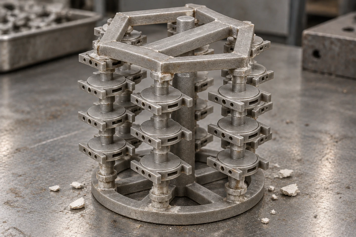
트리를 절단할 때에는 연결부가 끝까지 지지되도록 하고, 절단 흔적이 완성면을 침범하지 않게 가공여유를 남깁니다. 트리 위치와 부품의 대응도 이 단계에서 유지해야 이후 발견된 결함을 주입·냉각 조건으로 거슬러 확인할 수 있습니다. 절단·세정 후의 형상과 남은 소재를 확인한 다음 전면막 제거와 기능면 가공으로 넘어갑니다.
주형을 제거하고 트리에서 분리한 케이스에는 스템과 전면막이 남아 있을 수 있습니다. 이 영역을 제거하면 중앙이 열린 케이스가 됩니다. 절단은 연결부를 분리하는 단계이고, 정밀가공은 제품이 조립될 기준과 기능 치수를 완성하는 단계입니다. 두 작업의 목표를 나누면 어디까지 제거하고 어디서부터 정밀도를 확보할지 명확해집니다.
전면막을 제거하기 전후에는 케이스의 강성이 달라질 수 있습니다. 남아 있는 벽을 강하게 물어 가공하면 체결 중에는 원형으로 보이지만 풀었을 때 형상이 달라질 수 있으므로, 지지 위치와 체결 하중을 함께 검토합니다. 재체결 횟수보다 중요한 것은 각 공정에서 같은 기능 기준을 안정적으로 이어가는 것입니다.
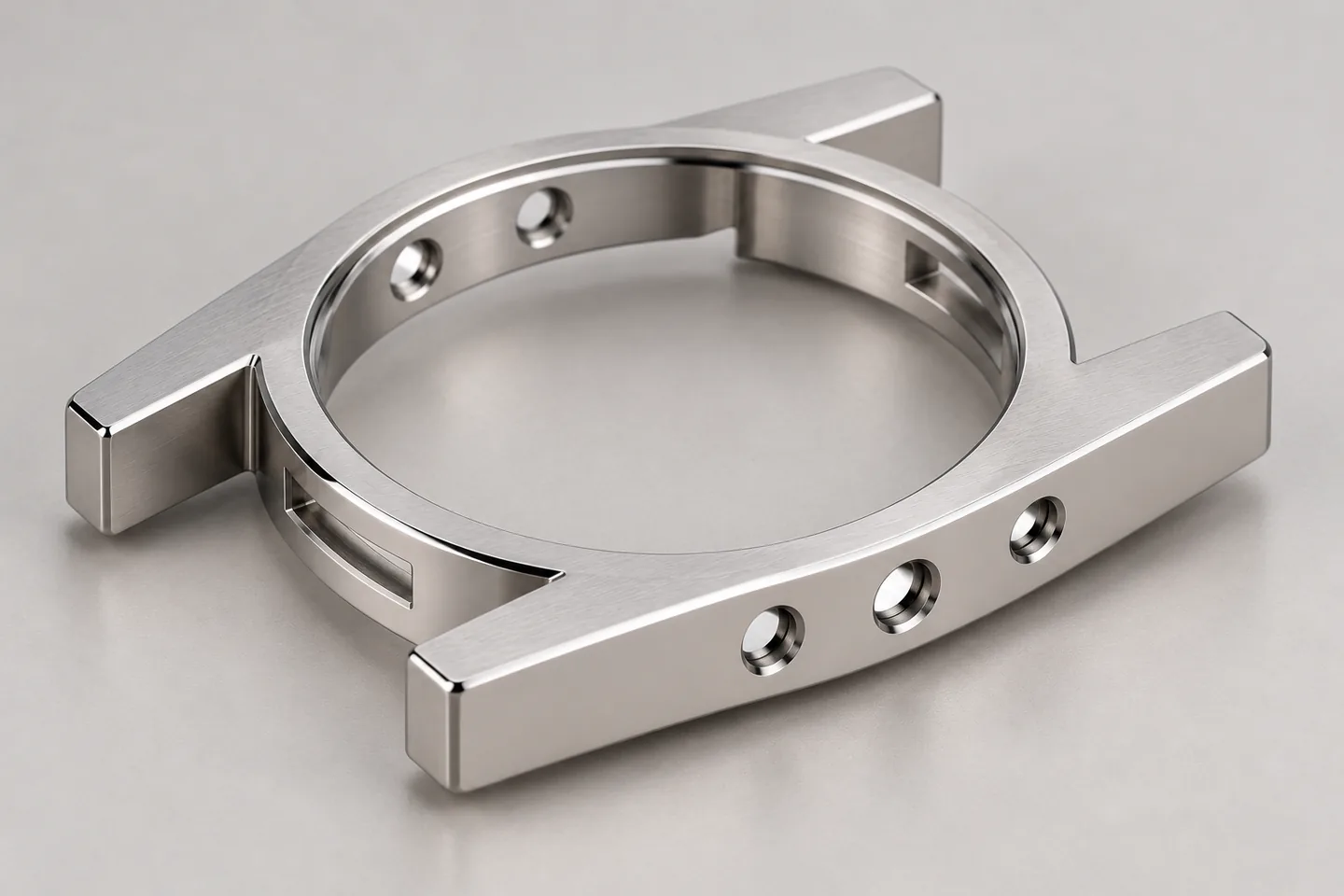
가공여유는 두께뿐 아니라 위치 오차를 포함합니다
씰 좌면이나 유리 안착면에 재료가 남아 있어도 주조품이 한쪽으로 치우쳤다면 전체 면을 가공하지 못할 수 있습니다. 필요한 가공여유는 제거할 표면층, 주조 편차, 기준 설정과 체결 오차를 고려하여 정합니다. 여유를 크게 잡는 경우에도 남는 벽 두께와 제거 시간, 가공 중 변형의 영향을 확인해야 합니다.
외경·내경과 환형 좌면은 선삭 경로가 유리할 수 있고, 직선 측벽·측면 홀·슬롯은 밀링이나 별도 공구 접근이 필요할 수 있습니다. 공정은 장비 명칭으로 먼저 고정하기보다 기능면 사이의 위치 관계와 공구 접근성을 기준으로 구성합니다. 작은 홀은 주조 상태 그대로 사용할지, 위치를 잡는 예비 형상으로 남기고 최종 가공할지 구분합니다.
주조품의 일반 공차와 완성 기능면의 공차도 분리합니다. 외관 비기능면에 조립면과 같은 공차를 일괄 적용하면 금형 수정과 검사 부담이 늘어날 수 있습니다. 반대로 씰이나 끼워맞춤에 필요한 조건을 ‘정밀주조’라는 공법 이름만으로 대체하면 조립 문제가 남습니다.
9. 곡면·모서리를 보존하는 외관 연마와 표면 처리
시계케이스의 외관은 밝기뿐 아니라 곡면의 흐름과 모서리 경계로 평가됩니다. 주조면의 흔적을 없애려고 한 부분을 오래 연마하면 대칭 형상이 달라지거나 얇은 모서리가 둥글어질 수 있습니다. 경면, 헤어라인과 무광의 구역을 나누고 각 마감이 만나는 경계를 도면과 견본으로 연결합니다.
연마는 표면을 제거하는 공정입니다. 표면 아래에 존재하던 결함이 노출될 수 있으므로, 초기 주조면이 깨끗해 보인다는 이유만으로 최종 외관을 확정하지 않습니다. 외관 불량이 반복될 때에는 마지막 연마 조건만 바꾸기보다 같은 위치의 패턴, 셸과 금속 내부 상태를 함께 확인합니다.
전해연마·세정·부동태화의 역할
전해연마는 표면의 미세 돌출부를 제거하고 표면 상태를 조정하는 데 사용됩니다. 적용 결과는 재질, 초기 표면과 처리 조건에 좌우되며, 깊은 내부 기공을 채우는 과정은 아닙니다. 작은 홀의 입구나 날카로운 경계, 치수에 민감한 좌면에서는 처리 후 형상도 평가해야 합니다.
연마재, 금속 이물과 세정 잔사가 남으면 외관과 내식성 평가에 영향을 줄 수 있습니다. 기계연마, 필요한 표면 처리, 충분한 세정과 건조를 연결하고 최종 상태를 기준으로 판정합니다. 광택이 높다는 사실과 오염이 없다는 사실은 같지 않습니다.
부동태화는 단순히 광택을 높이는 작업과 구분하여 표면의 내식성 요구에 연결합니다. 전해연마로 부동태 상태를 확보하는 경우에도 재질과 처리 전 표면, 전처리·후세척 및 검증 조건이 중요합니다. 별도 부동태화 처리의 필요 여부는 적용 사양과 최종 표면의 검증 결과로 정합니다.
표면 품질 기준은 관찰 거리와 조명, 검사 구역을 정해야 반복 적용할 수 있습니다. 육안으로 보이는 흠집과 광택 경계, 측정이 필요한 거칠기, 기능면의 평탄도는 서로 다른 평가 항목입니다. 특히 넓은 경면의 물결처럼 보이는 형상은 미세 거칠기 수치 하나만으로 충분히 설명되지 않습니다.
10. 케이스의 기능으로 연결하는 검증과 제조 사양
시계케이스 초정밀주조의 검증은 외관 합격과 치수 합격을 따로 끝내는 방식보다 최종 기능에 연결해야 합니다. 홀의 위치는 맞아도 내부 잔사가 남을 수 있고, 외관이 매끄러워도 기능면 아래에 결함이 있을 수 있습니다. 측정 수단별로 확인할 수 있는 범위가 다르므로 제품에서 중요한 위험 위치를 먼저 정합니다.
| 기능 또는 품질 목표 | 확인 방법 | 판정에서 구분할 한계 |
|---|---|---|
| 조립 위치와 안착 | 기준면에 연결한 치수·형상 측정, 홀 축선 및 상대 부품 조립을 확인합니다. | 개별 치수 합격만으로 전체 조립 관계가 보장되지는 않습니다. |
| 외관·표면 개구 결함 | 정해진 조명의 외관 검사와 확대 관찰, 필요 시 침투탐상을 적용합니다. | 침투탐상은 표면에 열린 결함을 대상으로 하며 닫힌 내부 결함을 모두 확인하지 못합니다. |
| 내부 건전성 | 요구에 맞는 X선·CT 또는 단면 관찰로 위치와 분포를 평가합니다. | 검출 가능한 크기와 검사 조건을 확인하며 가상 3D와 실제 검사 결과를 구분합니다. |
| 재질·표면 상태 | 성분과 열 이력, 필요 조직·자기 특성 및 지정된 내식성 평가를 연결합니다. | 재질명이나 광택만으로 기능과 사용 적합성을 확정하지 않습니다. |
| 최종 내수성 | 씰·유리·후면 덮개·관통 부품을 포함한 조립 상태에서 요구 시험을 수행합니다. | 케이스의 주조 공법이나 핀홀 저감만으로 특정 방수 등급을 보장하지 않습니다. |
도면과 견본에 함께 담을 내용
제조 검토에는 완성 형상뿐 아니라 가공할 면, 남겨야 할 벽 두께, 홀의 관통 상태와 축선, 외관 마감 경계가 필요합니다. 기준면과 치수 측정 상태, 허용 가능한 표면 결함의 구역, 재질·열처리·표면 처리 요구도 함께 정리합니다. 수량과 반복 생산 계획은 금형 캐비티와 트리 구성, 검사 방식의 선택에 연결됩니다.
시제품 단계에서는 주물 하나의 최종 치수만 보지 않고 트리 내 위치, 처리 전후 상태와 가공량을 연결하여 기록합니다. 형상 보정이 필요한지, 셸과 주입 조건을 조정해야 하는지, 치구 기준을 바꿔야 하는지가 구분되어야 같은 문제를 반복하지 않습니다. 이후 생산 조건이 바뀌면 영향을 받는 기능과 측정 항목을 다시 확인합니다.
주조품을 완성 형상에 가깝게 만드는 이점은 절삭 시간을 줄일 가능성에 있습니다. 다만 금형·셸·열처리·후가공과 선별 비용을 함께 보아야 실제 제조 경제성을 판단할 수 있습니다. 미세 형상을 안정적으로 전사하고, 금속을 필요한 위치까지 전달하며, 최종 조립 기준을 보존하는 공정이 함께 갖추어질 때 시계케이스의 형상 자유도와 반복 생산 품질을 연결할 수 있습니다.
English edition — Precision investment casting for watch cases
Precision in a watch case depends on more than its finished outline. Small lateral holes, thin walls, metal delivery paths, solidification shrinkage and machining datums must work together. A lost-wax process builds the required geometry into a wax pattern, transfers it into a ceramic shell and produces a metal blank whose critical assembly surfaces can be finished by machining.
1. Designing both the casting and the finished case
A case may combine a circular body, parallel side walls, transverse holes and curved-wall slots. Some features can remain as cast, while others require controlled machining. The useful starting point is to define these surfaces separately, rather than apply one accuracy requirement to the entire component.
The illustrated process retains a temporary front membrane in the region that will eventually become the opening for glass or a display. Stems connect near its centre along the case thickness direction. The membrane and stems belong to the manufacturing geometry; they are subsequently removed. Designing only the finished open ring would omit these connections and the associated separation operations.
The temporary material also affects cooling, local thickness and machining volume. Its shape must therefore be considered together with filling, feeding and tool access. The interactive models use symbols such as D, W, H and t to explain geometry. They do not supply production dimensions or tolerances, and the individual functions of lateral holes depend on the eventual assembly.
2. Wax tooling and side-core withdrawal
Holes directed through a side wall cannot always be released by opening the die vertically. Side cores form the required spaces in the wax and must withdraw along suitable paths before the pattern is removed. In a two-cavity arrangement, core movement, die opening and pattern support must avoid interference and damage to thin features.
Core stiffness and location matter as much as the nominal cavity dimensions. A slender projection can be influenced by injection pressure and release resistance. A slightly tilted core may leave a normal-looking entrance while altering the hole axis or the remaining wall thickness. Support length, locating interfaces and wear therefore belong in the tooling review.
Flash and mismatch in a wax pattern can be transferred through the shell into metal. Repeated defects should be addressed at their source rather than routinely removed at the final finishing stage. Die compensation must also account for the process chain; the cavity is not simply an unmodified copy of the finished metal case.
3. Preserving the wax pattern
Wax is readily removable, but its geometry requires controlled handling. Injection, cooling, release, storage and tree assembly can affect thin side walls and extended ends. Die and wax temperatures, packing conditions and cooling history influence dimensional stability, so successful filling alone does not demonstrate a stable process.
Patterns should be examined for blocked holes, flash, distortion and irregular joints. Repeated local repair can introduce additional variation and should not substitute for correction of a persistent tooling or processing issue. During tree assembly, stem alignment and pattern orientation also influence later drainage, drying and thermal conditions.
Measurements should avoid deforming the pattern and use consistent support, temperature state and elapsed time after release. Pattern measurements support process correction; they serve a different purpose from final acceptance measurements on a finished metal component.
Assembling axial stems and the upper runner
Aligned upper and lower stems connect the individual patterns into vertical columns. These columns are arranged horizontally and joined to the upper runner. Joints need continuity without open seams, while local heating must not distort the temporary front membranes. Smoothing a joint supports a continuous passage and stable shell reproduction, rather than merely improving its appearance.
Space between patterns also provides access for coating, drainage and drying. Closely spaced lugs can trap slurry or allow refractory particles to bridge a gap. Column alignment, stem joints and clearances should therefore be checked on the assembled tree, with its orientation tracked through subsequent processing.
4. Transferring small holes into the ceramic shell
An intended hole must remain excluded from the metal-filled volume. Ceramic formed through a wax opening can preserve that space after the wax is removed. Molten metal then occupies the former wax volume, and shell removal exposes the opening. Metal does not fill the hole and subsequently disappear from it.
This makes wetting, slurry access, drainage, drying, ceramic support and eventual removal integral to hole design. A narrow slot or long passage may appear satisfactory at its entrance while retaining air or incompletely dried material deeper inside. The ability to create a wax feature must therefore be considered alongside the ability to reproduce and clean it.
Vacuum treatment during slurry coating helps reduce trapped air in the slurry or at the pattern interface. It is not, by itself, evidence of vacuum melting or vacuum pouring. Slurry condition, surface cleanliness, dipping orientation and drainage remain relevant. Increasing shell thickness can improve support while changing heat transfer and restraint; reducing it is not automatically a route to higher precision.
Designed holes, shell-interface defects, gas porosity in metal and solidification shrinkage cavities are different phenomena. Their origins and inspection requirements differ. Removing coating bubbles cannot be presented as eliminating every internal metal defect. Shell thickness is also distinct from the wall thickness of the finished case.
Initial coating trials can examine wetting and drainage around the holes and walls of an individual pattern. Tree assembly changes access between patterns and the available drainage paths, so production conditions must also be checked on the actual tree. A thin first coat is not equivalent to a completed shell with the strength required for pouring.
Building and drying successive shell layers
The primary coat contacts the wax and defines the reproduced surface; subsequent layers support it. Dipping, drainage, refractory application and drying are repeated only when the previous layer can withstand the next operation. A single heavy application can leave pooled slurry and weak interfaces rather than a suitable laminated shell.
A pale external appearance does not establish adequate drying throughout the tree. Recesses between tiers and inside the lugs can receive less air exchange. Concentrated airflow on a primary coat can also create uneven drying. Temperature, humidity and airflow must suit the material system and geometry, avoiding both excessive external drying and insufficient drying in internal regions.
Dewaxing while preserving the cavity
Dewaxing removes most of the pattern material to create the cavity for metal. Steam autoclaves and dedicated thermal methods are among the available approaches; selection depends on the wax and shell system. Expansion and drainage must be considered together. Thick stems and thin case patterns should not be assumed to melt in the same way at the same time.
The discharge route, including the pouring opening, and shell orientation matter. After dewaxing, inspect for cracks, joint damage and residues. The quantity of recovered wax cannot demonstrate that every small ceramic feature remains sound. Support during handling should preserve the shell before subsequent heating.
Distinguishing firing from preheating for pouring
Firing after dewaxing removes remaining pattern constituents and establishes the shell condition needed for casting. Preheating establishes the thermal condition that helps the alloy fill thin sections before freezing. The operations may be contiguous, but their purposes and acceptance checks remain distinct.
A furnace display does not establish uniform temperature throughout a tree. Loading arrangement, hold conditions, shell size and transfer time before pouring affect the thermal state. Raising metal temperature alone to compensate for an excessively cooled mold can introduce other problems. Shell and alloy conditions should be set together.
5. Tree layout, filling and feeding
Patterns with approximately horizontal circular faces can be stacked through axial stems. Upper runners connect the columns and provide metal delivery paths. An illustrative layout of six positions and four levels contains twenty-four patterns. This describes an arrangement, not a corresponding productivity multiplier or a guaranteed number of accepted castings.
Tree size depends on shell-building equipment, handling stiffness, drying access, thermal conditions and later separation. Upper and lower positions need not experience identical filling and cooling histories. Identifying the position of each casting helps relate local dimensional or surface problems to the process.
Filling an empty cavity and feeding contraction during solidification are related but distinct. If a thin connection freezes while a thicker region still requires liquid metal, the feed path may be interrupted. Side-wall transitions, local bosses and membrane-to-stem junctions deserve attention. Animated paths illustrate connectivity; they are not computed flow rates, temperatures or validated solidification predictions.
Connecting preparation, pouring and cooling
Pouring conditions include mold preheat, metal cleanliness and temperature, available volume and continuity of delivery. Connected passages alone do not prevent entrained air or oxide contamination. Successful geometric filling and internal casting quality must therefore be evaluated separately.
Cooling and handling should account for different solidification behaviour in thin walls and thick connections. A tree should not be disturbed before it is sufficiently stable, nor should delicate cases be forced off their connections. The timing and method of shell removal influence distortion and damage as well as cleanliness.
6. Dimensional compensation across the process chain
A single enlargement factor cannot necessarily correct every dimension. Wax contraction, shell behaviour, solidification, cooling and mechanical restraint interact. External width, internal opening size, hole spacing and wall thickness can respond differently, even within one case.
A compensation value from one manufacturing example should not be transferred unchanged to another wax, alloy, shell or geometry. Shrinkage calculations must also identify their reference dimension: tooling, wax and metal values are not interchangeable denominators. Initial allowances can draw on experience, but actual parts are needed to validate them.
A useful measurement chain compares the same features at successive stages. Tooling-to-wax measurements help isolate injection and release effects. Wax-to-casting comparisons address shell and metal-stage variation. Measurements before and after heat treatment reveal dimensional changes that affect stock availability. Final machining and finishing measurements establish compliance with assembly requirements.
These comparisons require consistent datums. Aligning a distorted cosmetic surface differently at each stage can conceal the true local error. Functional reference surfaces and axes should govern both compensation decisions and final inspection.
7. Stainless steel, microstructure and heat treatment
Austenitic stainless steel selection involves cast structure, corrosion requirements, machining and finishing behaviour, and interaction with the assembled device. Alloy balance, solidification history and subsequent processing can affect retained ferrite and magnetic response. A grade designation alone does not describe every aspect of the finished casting.
Heat treatment should address the actual alloy, section, existing microstructure and required material state. Dimensional change must be considered alongside metallurgical objectives. Applying a temperature range does not automatically establish corrosion performance, low magnetic response and shape stability simultaneously.
When a controlled atmosphere is used to suppress oxidation, atmosphere control and microstructural objectives remain separate considerations. Limited surface oxidation does not demonstrate the required structure or magnetic properties. Heating, holding and cooling conditions must address the material requirement, followed by checks of surface condition, dimensions and microstructure.
Cold working can introduce martensite in some austenitic steels. Appropriate solution treatment can modify that contribution, but it is not a universal guarantee of completely non-magnetic castings. Where magnetic behaviour matters, define the required property and measurement locations. A hand-held magnet is not a substitute for a quantitative acceptance criterion, and low magnetic response does not establish radio-frequency transparency.
A process that introduces no additional nickel is not the same as a nickel-free alloy. Base composition, finished surface and any skin-contact requirements must be evaluated using the actual material and product specification.
8. Machining the opening and functional surfaces
Shell removal and controlled separation
Removing the cooled ceramic reveals a metal assembly corresponding to the wax tree. The cases remain intermediate castings with front membranes and stems. Removing bulk shell material and clearing narrow holes or slots require different access considerations. Applying strong knock-off loads through a slender lug can cause local damage even when the overall shape appears intact.
Support the connection during cutting and retain sufficient material to keep cut marks outside the finished surface. Preserve the correspondence between each part and its tree position so later defects can be related to pouring and cooling. Check the cleaned blank and remaining stock before removing the front membrane and machining functional surfaces.
After shell removal and separation, the casting may retain stems and its temporary front membrane. Removing these regions creates the open case. Separation removes manufacturing connections; precision machining establishes assembly references and functional dimensions. Their objectives should be defined independently.
Case stiffness can change substantially when the front membrane is removed. Clamping a thin wall excessively can produce an apparently correct feature while restrained, followed by a different shape after release. Support position, clamping load and datum continuity are therefore important when planning the machining sequence.
Stock allowance must cover more than a nominal surface-removal depth. Casting displacement, local distortion and locating uncertainty can prevent complete machining even where material appears to remain. Excessive stock, however, increases removal time and can affect remaining wall thickness or machining deformation.
Turning may suit circular diameters and annular seats, while lateral holes, straight faces and slots can require different tool access. Decide whether a small opening is used as cast or serves as a preliminary feature for final machining. General casting tolerances and the requirements of sealing or mating surfaces should remain distinct.
9. Finishing without losing the designed geometry
A watch case is judged by the continuity of its curves and the definition of its edges as well as by brightness. Concentrated polishing can soften a boundary or alter symmetry. Mirror-polished, brushed and matt regions should therefore have defined boundaries and appropriate reference samples.
Polishing removes material and can expose subsurface defects. A satisfactory initial casting surface does not establish final cosmetic quality. Repeated defects in one location should be traced through the wax, shell and metal stages rather than attributed only to the final polishing operation.
Electropolishing modifies the surface through controlled material removal; it does not fill deep internal cavities. Its effect depends on the alloy and initial condition. Small hole entrances, sharp edges and dimensionally sensitive seats need evaluation after treatment. Cleaning and drying must also address abrasive, metallic and chemical residues.
Passivation addresses the corrosion-related surface condition rather than brightness alone. Where electropolishing is used to establish a passive surface, alloy selection, initial condition, pretreatment, post-cleaning and verification remain relevant. The applicable specification and verification of the final surface determine whether a separate passivation treatment is required.
Inspection conditions should define lighting, viewing distance and surface zones. Visible scratches, gloss boundaries, measured roughness and geometric waviness represent different characteristics. One roughness value cannot fully describe the visual distortion of a broad reflective surface.
10. Verification and manufacturing specifications
Inspection should connect each method to a product function. Dimensional and geometric measurements establish alignment and seating. Visual examination and magnification address cosmetic defects. Where appropriate, penetrant testing examines surface-connected discontinuities, while X-ray, CT or sectioning can provide information about internal features and defects. Each method has its own detection limits and conditions.
Internal quality is not adequately described by one overall porosity value when defect location matters. A discontinuity beneath a sealing seat may have different implications from one elsewhere. Inspection plans should identify the relevant locations, detectable feature size and acceptance criteria without treating an illustrative 3D model as actual CT evidence.
Water resistance depends on the assembled system, including glass, seals, the back and components passing through the case. A casting process or reduction of pinholes alone does not establish a water-resistance rating. Material, surface and magnetic requirements likewise need their own appropriate verification.
Production drawings should identify finished geometry, machined regions, minimum remaining walls, hole requirements, datums and cosmetic boundaries. Prototype records should connect tree position, process stage, dimensional change and material removal. This distinguishes a tooling correction from a shell, pouring or fixture adjustment.
The economic value of a near-net-shape blank lies in the possibility of reducing unnecessary removal while maintaining reliable functional surfaces. Tooling, shell production, heat treatment, finishing and rejection costs must also be considered. Precision emerges from the complete manufacturing chain, rather than from the name of a casting method alone.
추가 정보
주제 요약
시계케이스 초정밀주조는 측면 코어를 이용한 왁스 형상, 미세홀의 세라믹 전사, 다층 트리의 금속 전달과 정밀 후가공을 연결하는 제조 설계입니다. 주조품의 전면막과 스템은 공정을 위한 임시 형상이며 제거 후 개방 케이스가 됩니다. 최종 품질은 주조 단계의 정확도와 조립 기능면의 가공·검증을 함께 평가합니다.
핵심 포인트
- 설계된 미세 관통홀과 원하지 않는 핀홀 결함을 구분합니다.
- 슬러리 진공 처리는 기포와 전사 품질에 관계하며 모든 금속 내부 결함의 제거를 뜻하지 않습니다.
- 금형·왁스·주조·열처리·후가공 단계에서 같은 기능 치수를 추적합니다.
- 주입을 위한 전면막·스템과 완성품에 필요한 가공여유를 함께 설계합니다.
- 치수·외관·내부 건전성·재질 상태와 최종 내수성은 각각 적합한 방법으로 확인합니다.
자주 묻는 기술 질문
미세홀을 주조로 만들면 이후 홀가공이 필요하지 않습니까?
요구하는 직경·축선·위치와 표면 상태에 따라 달라집니다. 주조 상태로 사용하는 형상과 최종 정밀가공을 위한 예비 형상을 구분해야 합니다. 세라믹 잔류와 실제 관통 상태도 확인합니다.
전면이 막힌 주조품으로 만드는 이유는 무엇입니까?
제거 예정인 전면막에 중심축 방향 스템을 연결하여 트리와 금속 전달 경로를 구성할 수 있습니다. 이 부분은 최종 조립 구조에 남지 않으며 분리·절삭 과정에서 제거합니다. 두께와 연결부는 충전·응고·제거량을 함께 검토합니다.
진공 처리만으로 핀홀을 모두 없앨 수 있습니까?
슬러리 코팅 단계의 진공 처리는 포획 공기를 줄이는 수단입니다. 금속 내부 가스와 응고 수축에 의한 결함은 다른 원인과 관리 항목을 갖습니다. 공정과 검사 결과를 나누어 평가해야 합니다.
모든 치수에 같은 수축률을 적용할 수 있습니까?
형상·재질·왁스·셸과 구속 조건에 따라 달라집니다. 외형과 개구부, 홀 중심거리 등이 서로 다른 편차를 보일 수 있으므로 동일 위치의 단계별 측정으로 금형 보정량을 검증합니다.
정밀주조 케이스의 방수 성능은 어떻게 확인합니까?
케이스의 내부 건전성과 기능면 가공을 확인하고, 유리·씰·후면 덮개·관통 부품을 포함한 최종 조립 상태에서 요구하는 내수성 시험을 수행합니다. 공법 이름이나 매끄러운 외관만으로 특정 등급을 보장하지 않습니다.
관련 기술
관련 키워드

Related posts
스마트링 금속 외장: 센서 창·내측 수지·절연 공간의 정밀 설계
롤러블폰 힌지 구조: 분절 지지 바·초소형 롤러와 화면 전개 설계

금속 외장 표면 DLC 코팅: 비커스 경도 1014.5로 살펴보는 내마모성과 표면 설계
CNC 가공에서 MIM 전환: 생산 수량·공차·후가공 원가 비교
