누름식 메탈 밴드 체결장치: 조작력과 체결 유지력을 함께 설계하는 방법
누름식 메탈 밴드 체결장치
조작력과 체결 유지력을 함께 설계하는 방법
누름식 메탈 밴드 체결장치 설계의 출발점은 손톱으로 작은 조작부를 밀어 둔 채 체결 위치까지 맞추어야 했던 불편입니다. 손끝이 접근하기 쉬운 누름면으로 조작을 옮기되, 손을 놓으면 핀이 충분히 복귀해 체결 하중을 지지해야 합니다. 버튼을 움직이는 힘, 핀의 후퇴 거리, 복귀 동작과 잠금부의 맞물림을 함께 검토하는 이유입니다.
버튼을 무겁게 만드는 것만으로 체결이 견고해지지는 않습니다. 반대로 가벼운 조작감만을 목표로 복귀 여유를 줄이면 핀이 중간에서 멈출 수 있습니다. 설계의 기준은 의도한 조작에서는 충분히 해제되고, 조작하지 않은 상태에서는 맞물림이 유지되며, 손을 놓으면 체결 가능한 위치로 돌아오는 것입니다.

손톱으로 밀던 작은 조작부를 손끝으로 누르는 면으로 바꿉니다
기존 스프링바 방식에서는 작은 핀이나 레버를 안쪽으로 밀어 핀을 짧게 만든 상태에서 밴드를 장착하거나 분리합니다. 손톱 끝을 조작부에 걸어 밀어 두고, 다른 손으로 시계와 밴드를 지지하면서 체결 위치를 맞추는 방식입니다. 삼성의 공식 교체 안내도 전통적인 스프링바를 손톱 또는 도구로 안쪽으로 누르는 조작을 명시합니다.
삼성전자서비스의 기존 밴드 장착 안내는 한쪽 스프링바 끝을 시계의 홈에 먼저 넣은 다음, 반대쪽 끝을 안쪽으로 밀어 연결하는 순서로 설명합니다. 아래 두 장의 공식 안내 그림은 이 장착 순서를 보여 줍니다.
한쪽 핀을 체결 홈에 삽입
시계와 밴드를 지지하면서 먼저 한쪽 끝의 위치를 맞춥니다.
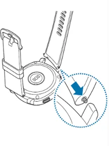
반대쪽을 안쪽으로 밀며 정렬
작은 조작부를 밀어 둔 상태에서 반대쪽 핀을 체결 위치에 맞춥니다.

작은 조작부의 유지와 위치 정렬이 겹치는 구간
이 순서를 조작 설계 관점에서 보면, 사용자는 핀을 후퇴시킨 상태로 유지하는 동작과 밴드의 위치·각도를 맞추는 동작을 동시에 수행합니다. 손톱이 짧거나 조작부 주변의 여유가 작으면 손끝의 접근이 제한될 수 있습니다. 정렬하는 동안 손끝이 작은 레버에서 벗어나면 핀이 먼저 돌출되어 다시 눌러야 하므로, 조작력 자체가 크지 않아도 장착이 번거로워질 수 있습니다.
누름식 조작부는 손톱으로 작은 돌출부를 찾아 미는 동작을, 구분된 누름면에 손끝으로 힘을 가하는 동작으로 바꾸는 설계입니다. 삼성의 Galaxy Watch6 디자인 자료 역시 이전 스프링바 구조와 원버튼 방식의 차이를 밴드 교체 편의의 개선으로 설명합니다. 메탈 밴드에 적용할 때도 버튼의 위치·면적·높이를 실제 손끝의 접근 조건에 맞추는 것이 우선입니다.
설계 목표는 핀을 후퇴시키는 조작을 쉽게 유지하면서 체결 위치를 맞출 수 있도록 하는 것입니다. 버튼을 누르는 방식에서도 핀과 상대 구멍의 정렬은 필요하며, 손을 놓은 뒤 양측 핀이 충분히 맞물려야 합니다. 교체 편의는 재시도 횟수와 조작 유지의 안정성으로, 체결 안전성은 복귀·맞물림·유지력으로 나누어 확인합니다.
누름부는 조작을 전달하고, 잠금부는 체결 하중을 지지합니다
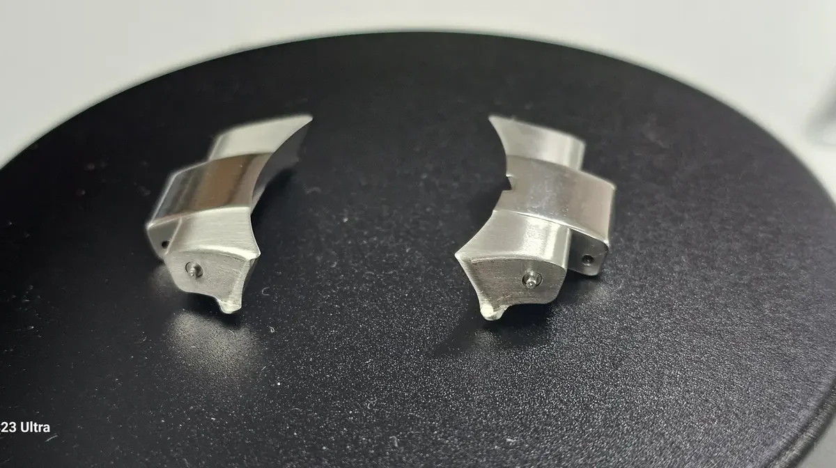
이 메탈 밴드 링크에서는 뒷면 중앙의 길쭉한 둥근 사각 돌출부가 누름부입니다. 이를 누르면 측면 단면의 작은 원형 핀이 몸체 안으로 들어갑니다. 측면 핀은 직접 누르는 버튼이 아니라 체결 위치에서 후퇴하는 부품입니다. 손가락의 입력 방향과 핀의 이동 방향을 먼저 구분해야 조작력과 이동량을 올바른 위치에서 평가할 수 있습니다.
누름식 메탈 밴드 체결장치의 설계에서는 두 가지 경로를 따로 추적합니다. 하나는 손가락의 힘이 누름부를 거쳐 핀의 이동으로 이어지는 작동 전달 경로입니다. 다른 하나는 밴드에 가해진 외력이 몸체·핀·상대 체결부를 거쳐 전달되는 체결 하중 경로입니다. 두 경로가 만나는 위치에서 마찰과 변형이 발생하면 조작감과 유지력이 서로 영향을 받습니다.
손가락 → 누름부 → 운동 전달 → 핀 후퇴
입력 힘과 실제 해제 위치를 확인합니다.밴드 몸체 → 핀 접촉부 → 상대 체결부
맞물림·지지 조건과 변형을 확인합니다.외형이 비슷하더라도 내부 전달 방식에 따라 힘과 변위의 관계는 달라집니다. 내부 스프링 형식이나 전달비가 확인되지 않은 상태에서 버튼 이동량과 핀 후퇴량을 같다고 둘 수 없습니다. 개발 단계에서는 버튼 위치와 양측 핀 위치를 함께 측정해 실제 관계를 확보합니다.
조작력은 최대값보다 힘이 변하는 과정으로 평가합니다
최대 조작력이 같아도 처음부터 저항이 큰 장치와 해제 직전에 힘이 급증하는 장치는 다르게 느껴집니다. 초기 유격, 힘이 증가하는 기울기, 중간 걸림과 끝단의 단단함을 함께 보면 조작감의 차이를 설명할 수 있습니다. 따라서 누름과 복귀를 한 쌍의 힘–변위 곡선으로 기록하고, 곡선 위에 핀이 완전히 해제되는 위치를 대응시킵니다.
버튼 면적·높이와 실제 접근 방향
같은 입력 힘도 손가락이 닿는 면적과 모서리 형상에 따라 국부 압박감이 달라집니다. 조작면을 넓히면 접촉을 분산시키는 데 도움이 될 수 있지만, 주변 몸체가 손끝의 진입을 막으면 넓은 면을 충분히 사용하지 못합니다. 착용 상태에서 손가락이 들어가는 각도, 손톱의 간섭, 인접 링크와의 여유까지 포함해 확인합니다.
낮은 조작부 배치
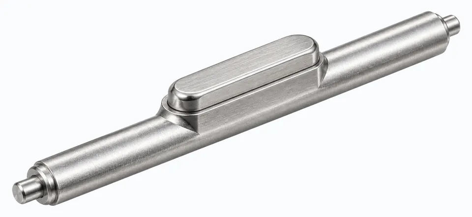
긴 바의 축선 가까이에 낮은 조작부를 두면 높이 방향의 외곽을 줄이는 구성을 검토할 수 있습니다. 그만큼 손끝이 들어갈 공간과 누름 깊이를 확보해야 하며, 주변 면에 너무 묻히면 조작 접근성이 떨어질 수 있습니다.
지지면을 둔 조작부 배치
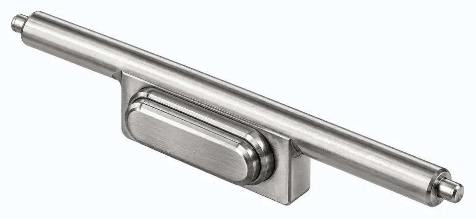
바의 아래쪽에 지지면과 조작 영역을 배치하면 손가락이 접근하는 면을 분명하게 구분할 수 있습니다. 다만 지지부가 차지하는 공간, 몸체와의 간섭, 가장자리를 누를 때의 기울어짐을 함께 검토해야 합니다.
이 배치 차이는 손가락과 장치가 만나는 조건의 차이입니다. 조작면이 넓거나 낮다는 이유만으로 더 작은 힘으로 동작한다고 판단하지 않습니다. 실제 조작력은 탄성 반력, 마찰, 부품 정렬과 운동 전달 관계를 함께 반영합니다.
긴 누름부의 중앙·편심 조작
길쭉한 버튼은 중앙만 정확하게 눌러 시험하면 양 끝에서 발생하는 문제를 놓칠 수 있습니다. 중앙과 좌우 끝 부근을 같은 조건으로 눌러 힘–변위와 양측 핀 후퇴량을 비교합니다. 편심 조작에서만 힘이 증가하거나 한쪽 핀이 덜 들어간다면 누름부의 기울어짐, 가이드 간극, 지지 강성과 정렬을 우선 확인합니다.
손톱 길이가 다른 사용자를 포함해 완전 체결까지의 재시도 횟수, 조작 중 손끝 이탈, 누름 상태를 유지하면서 정렬할 수 있는지를 확인합니다. 동일한 상대 체결부와 장착 조건에서 기존 레버식과 비교해야 조작부 변경의 효과를 구분할 수 있습니다.
시험기의 압자 형상·접촉 위치·누름 속도는 고정하고 기록합니다. 실제 손 조작은 별도로 평가해 손의 크기와 힘, 한 손 조작 여부, 건조하거나 젖은 접촉 상태에 따른 차이를 확인합니다. 보편적인 하나의 조작력 수치를 정하기보다 의도한 사용자의 조작 범위와 우발 접촉 조건 사이에서 허용 범위를 설정해야 합니다.
작동 거리는 양쪽 핀이 완전히 해제되는 위치에서 결정합니다
버튼이 끝까지 눌렸다는 사실과 체결이 풀렸다는 사실은 다릅니다. 버튼 이동량 일부가 초기 유격이나 부품의 탄성 변형에 사용될 수 있고, 좌우 핀의 이동량도 같지 않을 수 있습니다. 버튼 변위 s에 대한 두 핀의 후퇴량을 각각 기록하고, 실제 상대 부품에서 분리 가능한 위치를 확인합니다.
압자가 누름부에 닿는 기준을 정합니다.
버튼 이동과 좌우 핀 이동을 대응시킵니다.
양측의 잔여 맞물림과 간섭이 해소되는지 확인합니다.
해제 여유를 확보하고 과도한 내부 변형을 제한합니다.
해제 여유와 과행정 제한
좌측 핀이 먼저 해제되고 우측 핀이 나중에 해제된다면, 장치 전체의 유효 해제점은 늦게 해제되는 쪽을 기준으로 정합니다. 이 위치와 기계적 정지점 사이에는 조립 공차와 누름 위치 차이를 흡수할 여유가 필요합니다. 다만 정지점을 지나치게 깊게 두면 내부 탄성부나 전달부에 불필요한 변형이 생길 수 있습니다.
sstop은 정상 조작의 기계적 정지 위치이며, srelease,L과 srelease,R은 각 핀이 상대 부품에서 해제되는 버튼 위치입니다. 모두 같은 변위 기준에서 읽습니다. Δs가 양수라는 것만으로 충분하지는 않습니다. 공차·편심 조작·사용 후 변화 중 가장 불리한 조합에서도 필요한 최소 여유가 남는지 확인하고, 과행정 한계를 함께 설정해야 합니다.
긴 돌출량과 큰 작동 거리를 함께 검토하는 이유
핀의 유효 맞물림을 늘리면 하중을 전달하는 지지 길이를 확보하는 데 유리할 수 있습니다. 동시에 해제에 필요한 후퇴량이 증가할 수 있으므로 작동 거리, 내부 설치 공간과 손가락 조작 범위도 함께 확인해야 합니다. 유지력 검토에서 늘린 돌출량을 조작 거리 검토에 반영하지 않으면 끝까지 눌러도 핀이 걸리는 문제가 발생할 수 있습니다.
검증에는 최소·최대 치수 조건을 대표하는 상대 체결부가 필요합니다. 핀 축 방향의 길이 공차뿐 아니라 구멍 위치 오차와 기울어짐도 확인합니다. 축에 수직한 정렬 오차를 단순한 길이 덧셈으로 처리하면 실제 간섭을 놓칠 수 있습니다.
체결 유지력은 핀의 맞물림과 지지 조건에서 확보합니다
완전히 체결된 상태에서는 외력이 어느 접촉면으로 전달되는지 확인해야 합니다. 핀의 굵기만으로 유지력을 결정할 수는 없습니다. 핀이 받쳐지는 길이, 몸체와 상대 부품 사이의 간격, 구멍 주변의 두께와 강성, 하중 방향이 함께 작용합니다. 양측 핀이 있어도 공차와 비틀림 때문에 두 핀에 하중이 정확히 절반씩 걸린다고 가정하지 않습니다.

핀 끝의 도입부와 실제 하중 지지면
둥근 끝이나 모따기는 삽입을 유도하는 데 도움이 되지만, 그 구간 전체를 유효한 원통 지지 길이로 계산할 수는 없습니다. 상대 구멍의 입구에도 경사가 있으면 핀이 돌출되어 보이면서 실제 맞물림은 얕을 수 있습니다. 외력을 받는 접촉이 경사면에 집중될 경우에는 핀을 안쪽으로 밀어 넣는 성분이 발생하는지 확인해야 합니다.
삽입을 유도하는 면과 체결 하중을 받는 면은 역할을 구분합니다. 최종 조립 상태에서 충분한 지지 구간이 남는지, 공차와 하중 변형으로 접촉 위치가 도입부 쪽으로 이동하는지 확인합니다. 깊이를 늘리는 조치도 상대 부품의 바닥 간섭이나 핀의 작동 거리 한계를 함께 검토해야 합니다.
전단뿐 아니라 굽힘·접촉 변형까지 검토
핀을 지지하는 두 부품 사이에 간격이 있으면 핀에 굽힘이 추가될 수 있습니다. 이 경우 재료의 전단강도와 핀 단면적만 곱해 유지 하중을 정하는 계산은 실제 조건을 충분히 반영하지 못합니다. 상대 구멍 입구의 국부 접촉 압력과 눌림, 몸체의 벌어짐, 핀 가이드의 변형도 함께 확인합니다.
하중을 제거한 뒤 핀이 파단되지 않았더라도 미세한 잔류 굽힘이 있으면 가이드 마찰이 커지고 복귀가 불완전해질 수 있습니다. 따라서 유지 시험의 판정에는 이탈과 파손뿐 아니라 영구 변형, 잔류 유격, 시험 후 재조작·재체결 가능 여부를 포함해야 합니다.
외력이 걸린 상태의 해제 동작
밴드를 당긴 상태에서는 핀과 상대 구멍 사이의 접촉력이 커져 해제에 필요한 힘이 증가할 수 있습니다. 반대로 접촉면의 경사와 변형에 따라 외력이 핀 후퇴를 돕는 경우도 검토해야 합니다. 기본 조작 시험과 함께 규정된 인장·비틀림 조건에서 조작력과 해제 여부를 측정하면 두 기능의 상호작용이 드러납니다.
하중이 걸린 상태에서도 쉽게 분리되어야 하는지, 하중을 먼저 완화한 뒤 해제하도록 할지는 제품의 사용 방식에 맞춰 정합니다. 모든 하중 상태에서 가장 작은 힘으로 해제되는 것을 일률적인 목표로 삼지 않습니다.
복귀는 버튼 높이와 핀의 재맞물림을 함께 확인합니다
손을 놓았을 때 버튼이 올라와도 한쪽 핀이 상대 구멍의 입구에 걸려 있으면 체결은 완료되지 않습니다. 버튼의 원위치, 양측 핀의 재돌출, 상대 부품과의 유효 맞물림을 구분해 확인해야 합니다. 클릭음이나 손끝에 느껴지는 반응은 조작 피드백이지만 그 자체로 완전 체결을 증명하지는 않습니다.
복귀 말단에서 확보해야 하는 힘의 여유
탄성 복귀 방식을 사용하는 설계에서는 복원력이 마찰·간섭 등 복귀를 방해하는 저항을 이겨야 합니다. 특히 복귀 말단에서 탄성 반력이 작아지는 구조라면 끝부분의 여유가 부족해질 수 있습니다. 완전히 눌린 위치에서 힘이 크다는 사실만으로 전체 복귀를 보장할 수 없습니다.
q는 검토하는 가동부의 위치입니다. 두 힘은 각각 복귀 방향의 유효 복원력과 그 반대 방향으로 작용하는 저항력의 크기입니다. 내부 전달비가 있으면 힘을 같은 운동 좌표로 환산해야 하므로 버튼에서 측정한 힘과 핀의 축방향 힘을 그대로 빼지 않습니다. 이 관계는 준정적 설계 검토에 사용하며, 실제 복귀 시간과 정착 상태는 작동 속도·관성·감쇠를 포함한 시험으로 확인합니다.
복귀가 부족할 때 탄성력을 높이는 방법만 먼저 적용하면 누르는 힘도 커질 수 있습니다. 가이드 정렬, 버와 이물, 접촉면 손상, 누름부 기울어짐을 먼저 분리해 확인한 뒤 필요한 탄성 여유를 정합니다. 윤활을 적용한다면 재료와 표면 처리의 적합성, 이동·유출, 먼지 부착과 시간에 따른 상태 변화까지 관리해야 합니다.
부분 체결 상태의 구별
한쪽 핀만 상대 체결 구멍에 맞물린 상태, 상대 구멍이 약간 어긋난 상태, 버튼을 천천히 놓는 상태를 포함해 조립 동작을 검토합니다. 불완전 체결 상태가 정상 체결과 비슷하게 느껴지는지, 가벼운 위치 조정으로 완전히 복귀하는지, 정상 체결을 확인할 수 있는 피드백이 있는지 평가합니다. 충분한 맞물림을 확보하지 못한 상태를 정상 잠금 상태로 오인하지 않도록 해야 합니다.
유광 마감과 작동면의 정밀도는 별도로 관리합니다
3선 메탈 밴드 링크의 중앙 유광면과 양옆의 결 마감은 외관의 대비를 만듭니다. 그러나 외부 광택이 좋아졌다는 사실이 핀 가이드의 마찰이나 맞물림의 정밀도가 좋아졌다는 뜻은 아닙니다. 보이는 면의 마감 기준과 움직이거나 하중을 받는 면의 기능 치수를 분리해야 합니다.
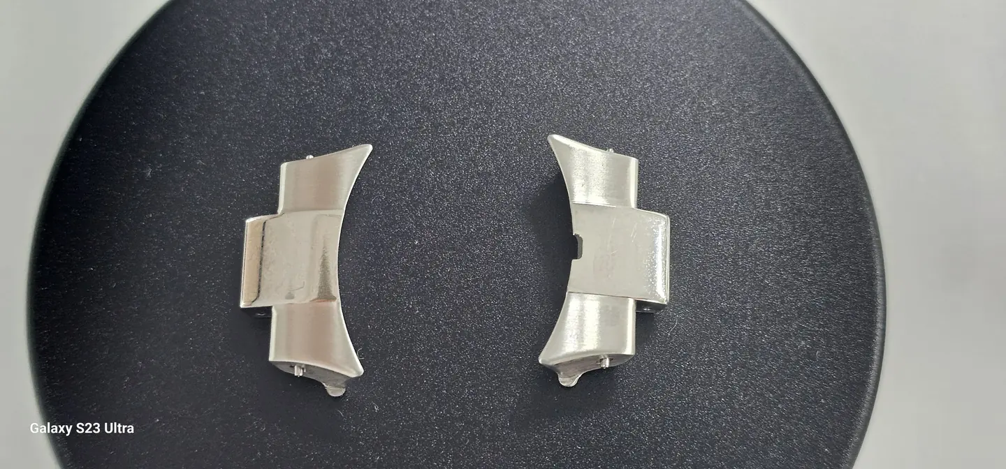
연마·도금 이후에 달라지는 기능 치수
연마는 모서리를 둥글게 하거나 국부 두께와 면의 경계를 바꿀 수 있습니다. 작동 간극을 형성하는 면이나 잠금 접촉면이 과도하게 연마되면 유격과 맞물림 위치가 변합니다. 도금·코팅을 적용하는 경우에는 반대로 두께 증가가 간극을 줄이거나 이동 저항을 키울 수 있습니다. 도면에는 가공 직후가 아닌 최종 표면 처리 상태의 기능 치수와 관리 면을 명확히 지정합니다.
조작부의 높이를 낮추어 돌출을 줄일 때에도 마감 제거량을 고려해야 합니다. 외관상 작은 높이 차이가 손끝의 접근성, 초기 접촉 위치와 유효 작동 거리를 바꿀 수 있습니다. 가장자리의 촉감과 피부 접촉부의 모서리 상태는 작동 성능과 함께 확인합니다.
이물과 마모가 만드는 장기 변화
연마제 잔류물과 미세 버는 좁은 가이드 안에서 작동 저항을 증가시킬 수 있습니다. 조립 전 세척·건조 상태와 이물 유입 경로를 확인하고, 반복 사용 후에는 마모분 축적과 접촉면 손상을 구분합니다. 조작력이 증가했다고 모두 탄성부 문제로 판단하거나, 유격이 증가했다고 모두 조립 공차 문제로 판단하면 원인을 놓칠 수 있습니다.
손목 착용 환경의 땀, 수분, 섬유 먼지와 화장품 잔류는 노출 조건에 따라 영향이 다릅니다. 지정한 환경과 세척 조건을 적용한 뒤 조작력, 복귀, 유효 맞물림과 유지 성능을 다시 평가해야 합니다. 재료 수준의 마찰·마모 시험은 후보를 비교하는 데 활용할 수 있지만 완성 조립체의 반복 수명을 대신하지는 않습니다.
조작·유지·반복 사용을 연결하는 검증 순서
개발 시편을 손으로 몇 번 눌러 보는 평가는 초기 느낌을 확인하는 데 유용하지만, 편차와 변화의 원인을 설명하기에는 부족합니다. 먼저 기본 조작과 유지 특성을 분리해 측정하고, 이후 편심 조작·외력·반복 사용을 결합합니다. 이렇게 해야 조작감 개선이 복귀나 유지 성능의 감소로 이어지는지 판단할 수 있습니다.
| 검증 단계 | 통일할 조건 | 판정에 사용하는 결과 |
|---|---|---|
| 기본 조작 | 압자 형상, 누름 위치·방향·속도, 초기 접촉 기준과 지지 위치를 정합니다. | 힘–변위 왕복 곡선, 양측 핀 해제 위치, 버튼과 핀의 복귀 위치를 비교합니다. |
| 편심·부분 체결 | 중앙·좌·우 누름, 상대 부품의 위치 편차와 버튼을 놓는 방식을 정합니다. | 기울어짐, 한쪽 핀의 잔여 간섭, 불완전 체결의 구별 가능성을 확인합니다. |
| 체결 유지 | 실제 상대 부품, 하중 방향·크기·속도와 유지 시간을 정합니다. | 이탈, 하중 중 변위, 영구 변형·잔류 유격과 시험 후 재조작 여부를 확인합니다. |
| 외력과 조작의 결합 | 밴드의 인장·비틀림 상태와 의도한 누름·우발 접촉 조건을 구분합니다. | 외력이 해제를 방해하거나 촉진하는지, 의도하지 않은 후퇴가 발생하는지 확인합니다. |
| 반복·환경 노출 | 반복 횟수, 중간 측정 시점, 노출물·온도·시간 및 세척 조건을 정합니다. | 조작력, 해제 여유, 복귀 시간·잔류 위치, 유격과 유지 성능의 변화를 비교합니다. |
확인 하중과 파괴 하중의 구분
규정된 하중을 견딘 뒤 기능이 유지되는지를 보는 시험과 파손까지 하중을 높이는 시험은 목적이 다릅니다. 파괴 하중을 정상 사용에서 허용할 하중으로 그대로 사용하지 않습니다. 낙하나 걸림처럼 하중이 빠르게 변하는 조건도 정적 당김 시험 하나로 대체하지 않으며, 사용 시나리오에 따라 별도 조건을 설정합니다.
측정 편차와 제품 편차의 분리
같은 시편을 다시 장착했을 때 값이 달라진다면 제품 변화에 앞서 지그와 정렬을 점검해야 합니다. 압입축과 실제 조작축이 어긋나거나 지그가 몸체를 과도하게 구속하면 힘이 다르게 측정됩니다. 재장착 반복, 다른 작업자의 설정과 기준 시편을 활용해 시험의 반복성과 재현성을 확인합니다.
양산 승인에는 평균값뿐 아니라 편심 조작에서의 분포, 가장 늦게 해제되는 핀, 가장 작은 복귀 여유와 반복 사용 후의 변화가 중요합니다. 목표 조작력·거리·유지 하중·반복 횟수는 적용 제품의 요구 조건으로 먼저 정하고, 시험 결과를 본 뒤 유리하게 바꾸지 않습니다.
맞춤 설계에서는 상대 체결부와 사용 조건부터 확정합니다
누름식 메탈 밴드 체결장치는 링크 단품만으로 성능을 완결할 수 없습니다. 핀이 들어가는 상대 부품의 위치와 형상, 조립 간격과 하중 조건이 함께 있어야 작동 거리와 맞물림을 결정할 수 있습니다. 외관을 먼저 확정한 뒤 남은 공간에 작동부를 맞추면 조작 여유와 유지 성능 사이의 조정 폭이 줄어들 수 있습니다.
개발 협의에 필요한 자료
- 연결 조건: 링크와 상대 체결부의 3D 도면, 핀 축선·구멍 위치, 장착 공간과 조립 기준을 준비합니다.
- 조작 조건: 손가락 접근 방향, 착용 중 조작 여부, 목표 조작감과 우발 접촉 시나리오를 정리합니다.
- 성능 조건: 허용 작동 거리, 체결 유지 하중의 방향, 반복 사용과 환경 노출 요구를 정합니다.
- 제작 조건: 재질 후보, 외관 마감 기준품, 최종 기능 치수, 예정 수량과 승인 일정을 공유합니다.
도면이 확정되기 전에는 상대 부품과 목표 사용 조건을 바탕으로 조작 공간과 하중 경로를 먼저 검토할 수 있습니다. 이후 시편에서 힘–변위와 핀 이동을 확인하고, 마감·조립·반복 시험 결과를 기능 공차와 공정 조건으로 연결합니다.
Push-Button Metal Band Fasteners: Designing Actuation Force and Retention Together
A push-button metal band fastener must permit deliberate release while maintaining engagement under the loads applied to the band. Button force, pin retraction, return behavior and load-bearing engagement are related, but they are not interchangeable measures. Making the button harder to press does not by itself establish stronger retention. Reducing elastic return force solely to improve feel can leave insufficient margin for complete re-engagement.
1. Replace Fingernail Manipulation with an Accessible Pressing Surface
Conventional spring-bar connections require a small pin or lever to be moved inward while the band is positioned for attachment or removal. Samsung’s official instructions for traditional spring bars explicitly describe pressing the pin inward with a fingernail or a tool. Its Korean service guide shows attachment in two stages: seat one end in the watch recess, then retract the opposite end to connect the band.
From an interaction-design perspective, this combines two tasks: maintaining pin retraction and aligning the band. A short fingernail or limited clearance around the lever can restrict access. If contact is lost during alignment, the pin can extend before reaching its mating position, requiring another attempt. This explains why assembly can be awkward even when the mechanism does not require a large force.
A push-button actuator transfers this input to a distinct pressing surface. Samsung’s Galaxy Watch6 design account likewise presents its one-button band attachment as an improvement in convenience over the preceding spring-bar arrangement. For a metal band, actuator location, contact area and height should support stable finger contact while the user positions the mating parts. These published examples establish the operating sequence and design rationale; they do not establish the internal mechanism or performance of the link discussed here.
The engineering objective is to maintain retraction conveniently during alignment. Pin-to-hole alignment and complete re-engagement remain necessary. Compare retry count, loss of finger contact and the ability to hold the actuator with representative users, including different nail lengths, under equivalent attachment conditions. Assess return, engagement and retention separately rather than treating easier handling as evidence of stronger locking.
2. Separate the Actuation Path from the Retention Load Path
In this metal band link, the elongated rounded rectangular feature at the center of the rear face is the actuator. Pressing it retracts the small round pins on the side end faces into the body. The side pins are retracting engagement members, not the finger-operated buttons. The direction of finger input and the direction of pin motion must be distinguished when defining measurements.
The actuation path runs from the finger through the actuator and transmission to the retracting pins. The retention load path runs through the band body, pin contacts and mating component. Friction and deformation where these paths interact can affect both operation and retention. Similar external forms do not establish identical internal transmissions, spring arrangements or motion ratios. Measure button displacement and both pin positions together rather than assuming a one-to-one relationship.
3. Assess the Force Profile and Access to the Actuator
Two mechanisms with the same peak force can feel different if one has high initial resistance and the other rises sharply near release. Record the complete press-and-return force–displacement profile, including free play, force buildup, local sticking and end-stop response. Associate the profile with the observed position at which the pins clear the mating component. A force peak or a tactile click alone does not establish release.
Contact area and edge geometry influence local finger pressure. A wider actuator may distribute contact, but surrounding geometry can prevent the finger from using that area. Evaluate finger approach, nail interference, adjacent links and access in the intended worn or unworn condition.
A low actuator close to the bar axis offers a compact height envelope, provided finger access and travel remain available. An actuator carried on a support surface below the bar provides a more distinct operating area but occupies additional space and requires checks for interference and eccentric loading. Neither layout proves lower force by appearance alone: elastic reaction, friction, alignment and transmission geometry determine the actual response.
For an elongated actuator, compare center, left and right contact positions. Increased force or incomplete pin retraction during off-center pressing can indicate tilt, guide clearance, support stiffness or alignment problems. Fix and document probe geometry, direction, location and test speed. Complement machine testing with representative hand operation, considering hand size, strength, one-handed access and dry or wet contact. Set the acceptable force range from intended use and accidental-contact scenarios rather than a universal force target.
4. Define Travel from Complete Release of Both Pins
Full button travel is not proof of complete disengagement. Initial clearance and elastic deformation can absorb part of the input displacement, and the two pins need not retract equally. Record each pin’s movement against button displacement and establish the actual clearance point in the mating assembly. Distinguish initial contact, pin retraction, complete release and the mechanical end stop.
The system release point is governed by the pin that clears last. In a common button-displacement coordinate, the release margin is Δs = sstop − max(srelease,L, srelease,R). A positive result is necessary but does not by itself establish sufficient margin. Assess the smallest margin across the relevant worst-case combination of manufacturing variation, off-center operation and changes through use, while limiting overtravel that could overload elastic or transmission elements.
Increasing effective engagement may improve the supported length of a pin, but it can also increase the retraction required for release. Assess engagement, operating travel, internal space and finger movement together. Use mating parts representing relevant dimensional extremes, including hole position and angular alignment. Transverse misalignment cannot be reduced to a simple axial tolerance sum.
5. Establish Retention through Engagement and Support
Pin diameter alone does not define retention. The supported length, gap between components, thickness and stiffness around the mating hole, and load direction all matter. Two pins cannot automatically be assumed to share load equally under tolerance variation and twisting.
A rounded tip or chamfer can guide insertion, but its full length is not equivalent to a cylindrical load-bearing engagement. Chamfers at the mating hole entrance can further reduce effective support. If load is carried on inclined contact surfaces, evaluate whether it creates a component that drives the pin inward. Separate lead-in geometry from the surfaces intended to carry service load, and verify that tolerances and deformation do not shift contact onto an unsuitable region.
A gap between supports can add bending to pin loading. A simple shear-strength-times-area calculation therefore may not represent the actual assembly. Include local bearing deformation, opening of the surrounding body and distortion of the guide. A pin can remain unbroken yet acquire permanent bending that increases friction and prevents reliable return. Retention acceptance should address disengagement, fracture, permanent deformation, residual play and the ability to operate and re-engage after unloading.
Band tension can increase contact resistance and release force. Depending on contact slope and deformation, external load may also assist retraction. Combine prescribed tension or twisting with controlled actuation to evaluate this interaction. Whether release under load is required, or the load should first be relieved, depends on intended use; minimum release force under every load condition is not an appropriate universal objective.
6. Verify Return and Actual Re-Engagement
A restored button height does not prove that both pins have entered their mating holes. Check actuator position, pin extension and effective engagement separately. Tactile feedback and sound can help the user recognize operation, but they do not independently verify full engagement.
For a design using elastic return, the restoring force must overcome friction, interference and other opposing forces throughout the required motion. A mechanism may have substantial force at full depression but insufficient force near the end of return. In a common motion coordinate, the quasi-static return margin can be expressed as Mreturn(q) = Frestore(q) − Fresist(q). The terms are the magnitudes of the effective force acting in the return direction and the opposing resistance. Button force and axial pin force must not be subtracted directly when an internal transmission changes the force ratio. Return time and settling still require dynamic testing that includes speed, inertia and damping.
Before increasing elastic force, isolate guide alignment, burrs, contamination, surface damage and actuator tilt; otherwise the corrective action may increase press force without removing the source of resistance. If lubrication is used, assess material and coating compatibility, migration, dust retention and changes over time.
Include one-pin engagement, slight mating-hole misalignment and slow button release. Determine whether incomplete engagement can be mistaken for normal locking, whether small positional adjustment permits full return, and whether the product provides useful confirmation of completed engagement.
7. Control Cosmetic Finish and Functional Dimensions Separately
The polished center and differently finished outer regions of the three-row metal link create visual contrast. External gloss does not establish good friction behavior inside a guide or accurate engagement. Define appearance criteria separately from dimensions and surfaces responsible for movement and load transfer.
Polishing can round edges and alter local thickness, clearance and contact geometry. Plating or coating can reduce clearance by adding thickness. Specify functional dimensions at the final surface-treatment condition, including protected or controlled surfaces. Actuator height after finishing can affect finger access, initial contact and available travel. Check edge comfort and skin-contact geometry as well as operation.
Residual polishing compound, burrs and wear debris can increase guide resistance. Control cleaning and drying before assembly, then distinguish debris buildup from surface damage after cycling. Sweat, moisture, textile dust and cosmetic residue require exposure conditions representative of use. Reassess force, return, engagement and retention after the specified exposure and cleaning sequence. Material-level friction or wear tests can screen candidates but do not replace endurance testing of the complete assembly.
8. Link Actuation, Retention and Endurance Validation
Start with controlled baseline measurements, then combine off-center operation, external loading and repeated use. Baseline actuation testing should fix the probe, contact point, direction, speed, initial-contact definition and support positions; record the full force–displacement cycle and both pin states. Partial-engagement testing should vary the relevant assembly offsets and release method. Retention testing should define the mating part, load direction, magnitude, rate and duration.
Combined tests should distinguish intended operation from accidental contact while the band is under specified tension or twisting. Endurance and environmental tests require an agreed number of cycles, intermediate measurement points, exposure materials, temperature, duration and cleaning conditions. Compare force, release margin, return time and residual position, play and retention through the test history.
A proof-load test that checks continued functionality and a destructive test that establishes failure behavior serve different purposes. Failure load is not automatically an allowable service load. Rapid loading from impact or snagging also requires consideration beyond a static pull test. After unloading, check residual deformation and operating function.
Separate product variation from measurement variation through remounting trials, operator setup checks and reference specimens. Misaligned loading or excessive fixture restraint can change measured force. Approval should consider the distribution under eccentric operation, the last pin to clear, the smallest return margin and changes after use—not only mean initial values. Define acceptance criteria from the intended application before assessing the results.
9. Begin Custom Development with the Mating Interface
The link alone cannot define assembly performance. Development inputs should include drawings or samples of the mating component, pin axes and hole positions, assembly spacing and datum scheme, available actuator space and finger approach. Agree on operating conditions, desired feel, accidental-contact scenarios, permitted travel, retention load directions, endurance and environmental requirements.
Material candidates, finish references, final functional dimensions, production volume and approval milestones complete the manufacturing brief. Before drawings are frozen, review the actuation envelope and load path together. Then connect measured force–displacement and pin movement with finishing, assembly and endurance results to establish functional tolerances and process controls.
추가 정보
주제 요약
누름식 메탈 밴드 체결장치는 조작력·핀 후퇴량·복귀·유효 맞물림을 함께 검토해야 합니다. 누름부의 힘과 체결 상태에서 외력을 지지하는 능력을 구분한 뒤, 실제 상대 부품을 포함한 시험으로 두 기능의 상호작용을 확인합니다.
핵심 포인트
- 뒷면의 긴 둥근 사각 돌출부가 누름부이며 측면의 작은 원형 핀이 안쪽으로 후퇴합니다.
- 최대 조작력뿐 아니라 힘–변위 왕복 곡선과 양측 핀의 완전 해제 위치를 확인합니다.
- 맞물림 길이·도입부·지지 간격·변형을 함께 검토하고, 복귀 완료와 정상 체결을 구분합니다.
- 최종 마감 상태와 반복 사용 후에도 조작·복귀·유지 성능이 요구 범위 안에 있는지 평가합니다.
실무 FAQ
기존 손톱 조작 방식과 비교할 핵심 항목은 무엇입니까?
작은 레버를 밀어 둔 채 위치를 맞추는 동작이 누름면 조작으로 얼마나 안정적으로 바뀌는지 확인합니다. 완전 체결까지의 재시도, 손끝 이탈, 누름 유지와 정렬의 동시 수행을 같은 조건에서 비교합니다. 조작 편의와 별도로 양측 핀의 복귀와 체결 유지력을 평가합니다.
조작력을 낮추면서 유지력을 확보할 수 있습니까?
작동 전달 경로와 체결 하중 경로를 구분해 검토할 수 있습니다. 불필요한 마찰과 편심을 줄이고 하중 지지면의 맞물림과 강성을 확보하는 방식입니다. 다만 내부 전달 구조와 접촉 조건에 따라 두 기능이 영향을 주므로 실제 조립체에서 함께 검증해야 합니다.
작동 거리는 버튼 이동량으로만 정합니까?
버튼 이동량과 좌우 핀 후퇴량을 함께 확인합니다. 양측 핀이 모두 해제되는 위치를 기준으로 정지점까지의 여유를 확보하고, 과행정에 따른 내부 부품 부담을 제한합니다.
버튼이 돌아오면 체결 완료로 판단할 수 있습니까?
버튼 높이와 양측 핀의 재돌출, 실제 맞물림은 별도 확인 항목입니다. 한쪽 핀만 걸리거나 핀 끝이 상대 구멍 입구에 멈춘 상태가 정상 체결처럼 느껴지지 않는지 검토해야 합니다.
양산 검토에 필요한 자료는 무엇입니까?
상대 체결부 도면·시편, 조작 방향과 장착 공간, 목표 하중과 반복 사용 조건, 재질·표면 마감 요구 및 예정 수량이 필요합니다. 도면 미확정 단계에서는 사용 조건과 연결 인터페이스를 먼저 협의할 수 있습니다.
기존 밴드 교체 방식의 공식 안내
- 삼성전자서비스 · 스프링바 밴드의 분리와 장착 — 한쪽 끝 삽입 후 반대쪽을 안쪽으로 밀어 연결하는 절차와 그림을 확인할 수 있습니다.
- Samsung 공식 지원 · 전통적인 스프링바 조작 안내 — ‘Armbänder mit klassischem Federsteg’ 항목에 손톱 또는 도구를 이용하는 조작이 명시되어 있습니다.
- Samsung Design · Galaxy Watch6 원버튼 밴드 개발 설명 — 기존 스프링바 구조와 버튼식 조작의 교체 편의를 비교합니다.
관련 기술과 부품 형상
관련 키워드
누름식 메탈 밴드 체결장치, 메탈 밴드 링크, 스프링바, 조작력, 힘–변위, 작동 거리, 핀 후퇴량, 복귀력, 체결 유지력, 유효 맞물림, 편심 조작, 공차 누적, 반복 내구, 표면 마감

Related posts
스마트링 금속 외장: 센서 창·내측 수지·절연 공간의 정밀 설계
시계케이스 초정밀주조: 미세홀·주입 구조·후가공을 연결하는 제조 설계
롤러블폰 힌지 구조: 분절 지지 바·초소형 롤러와 화면 전개 설계

금속 외장 표면 DLC 코팅: 비커스 경도 1014.5로 살펴보는 내마모성과 표면 설계