

스마트링 금속 외장: 센서 창·내측 수지·절연 공간의 정밀 설계
스마트링 금속 외장: 센서 창·내측 수지·절연 공간의 정밀 설계
스마트링 금속 외장은 작은 반지 안에서 외관, 착용감, 센서 정렬과 내부 부품 보호를 동시에 담당합니다. 얇은 금속 링을 정밀하게 만드는 것에서 그치지 않고, 피부 쪽 광학창과 수지 라이너, 접착층이 서로 간섭하지 않도록 조립 기준을 연결해야 합니다.
1. 금속 외장과 피부 접촉면의 역할 분리
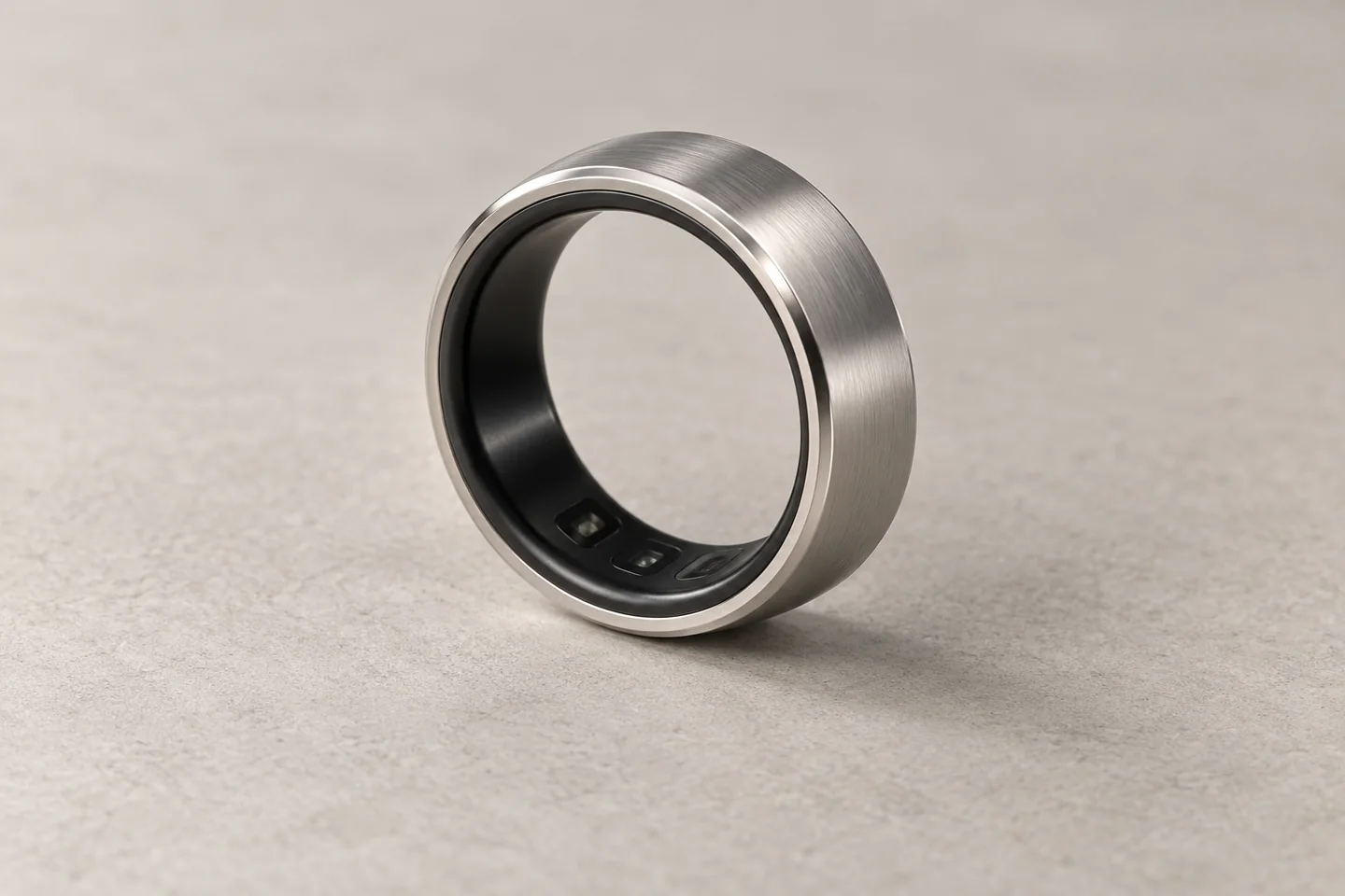
스마트링의 금속 외장은 손가락 움직임과 일상적인 접촉에 노출됩니다. 반면 광학 센서는 손가락 안쪽을 향하고, 회로와 배터리는 두 표면 사이의 제한된 공간에 배치됩니다. 따라서 외경과 내경 사이의 두께는 하나의 금속 벽 두께가 아닙니다. 금속, 조립 여유, 전자부품, 절연층과 피부 접촉면이 함께 사용하는 공간입니다.
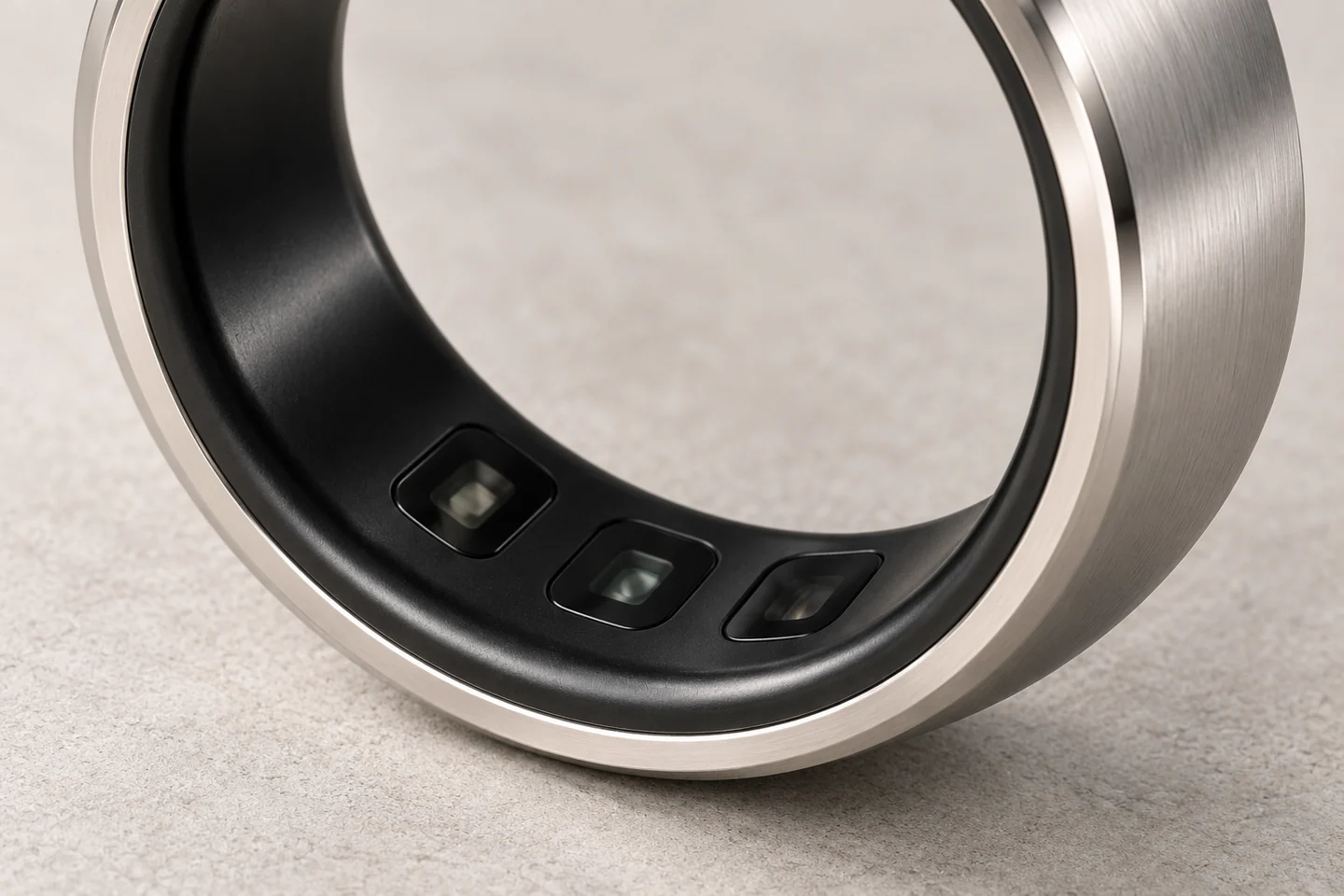
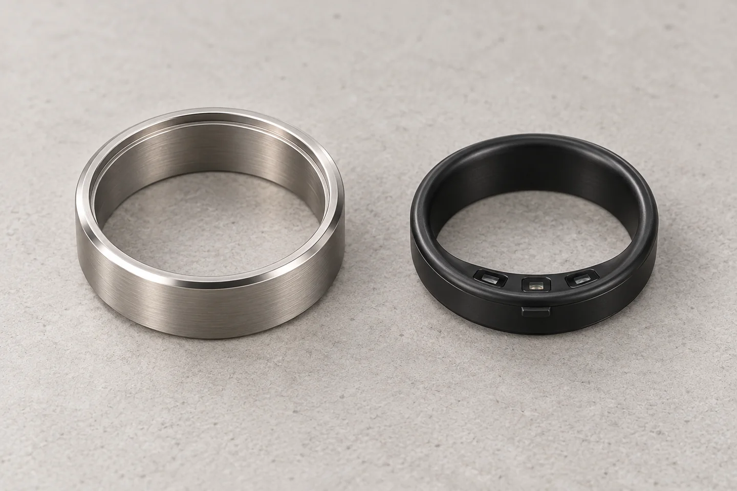
금속 외장과 수지 라이너를 조합하면 금속에는 외관과 구조 지지 역할을, 수지에는 내측 형상과 절연·광학 경계 역할을 배분할 수 있습니다. 센서 창은 빛을 통과시키고 그 주변은 불필요한 빛을 막도록 설계합니다. 같은 검정색이라도 파장별 투과율이 다르므로, 육안으로 어둡다는 이유만으로 차광재나 광학창 재료로 확정할 수 없습니다.
내측면까지 금속을 사용하는 스마트링도 존재합니다. 그러므로 수지 라이너는 모든 제품에 공통인 구조가 아니라 설계 선택지입니다. 금속 외장·내측 수지 구조에서는 강성을 확보하는 면, 피부와 닿는 면, 빛이 통과하는 면, 전기적으로 분리해야 하는 면을 처음부터 구분해야 불필요하게 두꺼운 외장을 피할 수 있습니다.
| 구조 영역 | 주요 기능 | 형상 설계의 초점 |
|---|---|---|
| 금속 외장 | 외관과 외부 하중을 담당합니다. | 박육부의 진원도, 가장자리 곡률, 라이너 지지면과 후가공 기준을 연결합니다. |
| 내측 수지 | 착용면과 내부 부품 사이의 경계를 형성합니다. | 센서 창 높이, 모서리 연결, 성형 수축과 조립 후 내경을 관리합니다. |
| 광학창·차광벽 | 필요한 광로를 열고 내부 광누설을 억제합니다. | 발광부·수광부의 개구, 차광벽 연속성, 창과 센서 사이 거리를 함께 정합니다. |
| 접착·절연 영역 | 부품을 고정하고 설계된 전기적 분리를 유지합니다. | 접착층 두께, 도포 경계, 경화 수축과 절연층 손상 가능성을 검토합니다. |
2. 센서 창은 구멍의 크기보다 광로의 경계가 중요합니다
반사형 광용적맥파(PPG) 센서는 발광부에서 나온 빛이 조직과 상호작용한 뒤 수광부에 돌아오는 변화를 사용합니다. 외장 설계에서는 회로의 처리 성능과 별개로, 빛이 어떤 경로로 수광부에 도달하는지 고려해야 합니다. 창의 하부 반사나 투명 재료 내부를 따라 직접 전달되는 빛은 원하는 조직 경로를 통과하지 않은 광누설이 될 수 있습니다.
창과 센서 사이의 공간을 크게 확보하면 조립은 편해질 수 있지만 광학적으로는 불리할 수 있습니다. 반대로 센서에 창을 무조건 밀착시키면 공차나 열변형이 센서 패키지에 하중을 전달할 수 있습니다. 필요한 간격은 선택한 센서의 광학 구조와 커버 재료, 공정 편차를 함께 반영해 정하며, 다른 웨어러블의 권장 수치를 그대로 적용하지 않습니다.
투과 영역과 차광 영역의 연결
발광부와 수광부 사이의 차광벽은 센서 기판 부근에서 끝나는 것보다 창 아래의 광누설 경로까지 연결되는지가 중요합니다. 창 하부 인쇄, 불투명 수지 리브, 모듈 내부 차광 구조는 서로 다른 높이에서 빛을 막습니다. 각 부품이 따로 적합해도 조립 후 틈이 열리면 직접 광누설이 발생할 수 있습니다.
다만 차광벽을 높이고 개구를 좁히는 방식만으로 문제를 해결할 수는 없습니다. 깊은 터널 형태의 창은 발광 범위나 수광 시야를 가릴 수 있습니다. 창의 유효 개구와 벽 높이는 센서의 광학 중심을 기준으로 검토하고, 모따기나 곡면 역시 빛의 입출사 경로에 포함합니다.
피부 접촉면의 단차와 센서 정렬
스마트링 금속 외장 안의 광학 모듈이 기울면 창과 센서 사이 거리가 위치에 따라 달라집니다. 라이너의 성형 단차나 접착제 넘침은 착용면을 바꾸고 피부와의 접촉 상태에도 영향을 줍니다. 외관상 매끄러운 면과 광학적으로 안정된 접촉면이 항상 같은 것은 아니므로, 센서 창 높이와 주변 곡률은 완성 조립체에서 평가해야 합니다.
여기서 필요한 제조 관리는 센서 알고리즘을 대신하는 것이 아닙니다. 지정된 광학 위치가 조립 후에도 유지되도록 창, 차광벽, 모듈 지지면의 형상과 위치를 관리하는 일입니다. 신호 품질은 피부 특성, 착용 상태와 움직임의 영향까지 포함하므로 기계 치수 하나만으로 보장할 수 없습니다.
3. 외경·내경·센서 창을 하나의 조립 기준으로 연결
스마트링은 원형이지만 모든 기능이 회전 대칭인 부품은 아닙니다. 센서 창, 내부 회로, 배터리와 충전 접점의 위치를 정하면 원주 방향 기준이 필요합니다. 외경만 잘 맞춘 링은 내부 부품의 회전 위치를 결정하지 못합니다.
기준 체계는 조립 방식에 맞춰 구성합니다. 예를 들어 한쪽 끝면을 축방향 기준 A, 라이너를 지지하는 원통면을 중심축 기준 B, 작은 키나 홈을 회전 위치 기준 C로 정할 수 있습니다. 센서 창 위치와 모듈 안착 높이는 이 기준 체계에서 연결하고, 외관 폴리싱으로 변하기 쉬운 모서리를 조립 기준으로 사용하는 것은 피합니다.
내측 수지는 금속 셸의 전체 면에 강하게 끼워 맞추기보다, 필요한 지지 구간과 접착 여유를 구분하는 방식으로 검토할 수 있습니다. 짧은 위치결정 구간은 동심 위치를 잡고, 별도의 접착 영역은 도포량과 경화 후 간극을 담당합니다. 단, 이 방식이 모든 조립에 적합한 것은 아니며 씰 경로·조립 방향·부품 변형 조건에 따라 지지 길이와 위치를 정해야 합니다.
조립을 쉽게 하려는 리드인 모따기는 유효 지지 길이를 줄입니다. 지나치게 큰 모따기나 연마로 둥글어진 어깨는 라이너가 예정된 위치보다 깊게 들어가거나 기울어지게 만들 수 있습니다. 도면에는 단순 외경 치수 외에도 기능면의 위치, 모서리 형상과 표면처리 제외 범위를 표시해야 합니다.
4. 평균 간극이 같아도 한쪽 접착층은 사라질 수 있습니다
외장 안지름을 Dh, 그 안에 들어가는 라이너의 조립 바깥지름을 Dl로 두면, 동심 상태의 반경 방향 간극은 g = (Dh − Dl)/2입니다. 이때 Dl은 손가락이 통과하는 착용 내경과 다른 치수입니다. 지름 차이를 반경 간극으로 그대로 읽으면 접착층 두께를 두 배로 잘못 해석하게 됩니다.
가상 공차 계산
Dh = 20.00 ± 0.02 mm, Dl = 19.90 ± 0.03 mm로 가정하면 명목 반경 간극은 0.050 mm입니다. 최악 조합에서는 최소 0.025 mm, 최대 0.075 mm가 됩니다. 여기에 중심 편심 e = 0.015 mm가 겹치면 국부 간극의 가능한 범위는 약 0.010~0.090 mm까지 넓어집니다.
위 수치는 공차 합산을 설명하기 위한 가정이며 실제 스마트링 사양이나 권장 접착 두께가 아닙니다. 진원도·원통도·표면 거칠기·접착제 유동과 경화 수축은 별도로 고려해야 합니다.
편심에 따른 원주 방향 간극 변화
명목 반경 간극 g₀ = 50 μm를 고정한 가상 계산입니다. g(θ) ≈ g₀ − e cos θ의 1차 근사를 사용하며, 지름 공차와 진원도는 이 그래프에 합산하지 않았습니다.
평균 간극이 같아도 편심이 커지면 최소 간극이 작아집니다. 위 본문의 10~90 μm 범위는 지름 공차와 편심 15 μm를 함께 적용한 별도의 최악 조합 계산입니다.
간극이 좁아진 쪽에서는 접착제가 밀려나거나 금속과 수지가 직접 접촉할 수 있습니다. 반대쪽에는 두꺼운 접착층이나 기포가 남기 쉽습니다. 그래서 평균 지름 합격만으로 접착 상태를 판단하지 않고, 동심 위치와 국부 형상까지 확인해야 합니다. 접착제는 재료별 권장 도포 두께와 경화 조건을 확인한 뒤 선정합니다.
열팽창 차이와 접합부 변형
금속과 수지는 온도 변화에 따른 자유 팽창량이 다를 수 있습니다. 비접합 상태의 단순 모델에서는 간극 변화가 Δg ≈ (αhDh − αlDl)ΔT/2로 표현됩니다. 라이너의 바깥지름이 외장 안지름보다 더 많이 증가하면 간극이 줄어드는 방향입니다.
실제로 접착된 조립체는 자유롭게 팽창하지 못합니다. 이 경우 치수 변화는 접착층의 전단·박리 응력, 수지의 변형과 시간 의존 거동으로 분배됩니다. 따라서 자유 팽창식만으로 접합 수명을 계산하거나 모든 수지에 동일한 열팽창계수를 적용해서는 안 됩니다. 선택한 재료의 온도별 특성과 접착층 두께를 반영하고 조립체 시험으로 확인해야 합니다.
5. 얇은 스마트링 금속 외장의 가공과 형상 유지
스마트링 금속 외장의 난점은 작은 크기 자체보다 얇은 단면과 기능면의 조합에 있습니다. 가공 중에는 척이나 지그가 링을 지지하지만, 탈착 후에는 지지력이 사라집니다. 클램핑 상태에서 원형으로 가공된 부품이 자유 상태에서 타원이나 다엽 형상으로 변할 수 있으므로 가공 중 측정값과 최종 자유 상태의 형상을 구분해야 합니다.
CNC 선삭과 국부 밀링의 분담
회전 대칭의 외경·내경·단차는 선삭 공정으로 연결하기 좋습니다. 센서 위치결정 홈이나 회전 방지 키처럼 비대칭인 부분은 별도 밀링 또는 복합 가공으로 형성합니다. 공정 사이에 기준을 다시 잡을수록 위치 오차가 추가되므로 기능면을 같은 기준에서 연속 가공할 수 있는지 검토합니다.
박육부에는 넓은 접촉 면적의 지지와 필요한 수준의 클램핑력이 중요합니다. 과도한 체결력은 변형을 키우고, 부족한 체결력은 미끄럼과 진동을 유발합니다. 황삭 단계에는 지지 강성을 남기고 마무리 단계에서 얇게 만드는 순서를 검토하되, 재질·소재 잔류응력·공구 접근성에 따라 가공 순서를 조정합니다. 지지 방법은 최종 내경과 조립 기준을 손상시키지 않아야 합니다.
MIM 적용을 판단하는 형상 요소
스테인리스 계열 등 MIM 적용이 검증된 재질에서 내부 리브·단차·위치결정 형상이 반복된다면, 여러 절삭 공정을 성형 단계로 옮기는 방안을 검토할 수 있습니다. 그러나 단순한 원형 외장이라는 이유만으로 MIM이 유리한 것은 아닙니다. 생산 수량, 크기별 금형 구성, 소결 변형, 후가공량과 외관 마감 비용을 함께 비교해야 합니다.
MIM 부품에서도 라이너 조립면, 끝면과 광학 모듈 기준부는 필요한 공차에 따라 후가공을 배분합니다. 얇은 링의 수축과 원형도는 게이트·충전·탈지·소결 지지 조건의 영향을 받습니다. 최종 외관면의 폴리싱으로 기능면 오차를 보정하려 하면 두께와 모서리 형상이 함께 변할 수 있으므로 성형, 소결, 후가공의 역할을 분리합니다.
외장 재질을 바꾸면 같은 형상에서도 강성, 질량, 절삭성, 표면처리와 접착 전처리 조건이 달라집니다. 티타늄이나 스테인리스라는 재료명만으로 제작법을 결정하지 않고, 구체적인 합금과 공급 상태, 형상 및 양산 조건을 확인해야 합니다.
6. 절연 공간과 무선 통신 영역의 설계 경계
절연은 금속과 기판 사이에 빈 공간이 보인다는 이유만으로 확보되지 않습니다. 조립 편심, 금속 버, 코팅 결함, 압축된 배선과 습기 등이 실제 분리 상태를 바꿀 수 있습니다. 도면에는 금속 모서리의 버 제거와 절연 부품 위치를 연결하고, 조립 압력으로 절연층이 손상되는 경로를 확인해야 합니다.
외관용 표면처리를 기능 절연층과 동일하게 취급하지 않습니다. 절연 기능으로 사용하려면 해당 막의 결함, 마모, 두께 편차와 전기적 특성을 별도로 검증해야 합니다. 필요한 절연 거리와 시험 조건은 전압, 회로 구조, 오염 조건과 적용 요구사항에 따라 정하며 스마트링이라는 제품명만으로 단일 수치를 지정하지 않습니다.
금속 외장은 안테나의 방사와 공진 조건에도 영향을 줍니다. 비금속 영역을 확보하는 설계가 있는 반면 금속 셸의 일부를 안테나 구조에 통합하는 방식도 있습니다. 따라서 센서용 투명창이 있다는 이유로 통신용 창까지 확보되었다고 볼 수 없습니다. 외장, 접지, 안테나와 인체의 관계를 함께 검토하고, 최종 외장·접착제·내측 수지가 포함된 조립 상태에서 통신 성능을 확인해야 합니다.
7. 표면 마감에서 접착·조립까지 이어지는 공정 설계
헤어라인이나 폴리싱은 빛의 반사를 조절하지만, 동시에 모서리와 얇은 부분에서 재료를 제거합니다. 외관면을 균일하게 만들면서 라이너 안착 어깨와 접착 영역을 보존하려면 마감 경계를 먼저 정의해야 합니다. 도금·코팅이 들어가는 경우에도 치수 증감과 접착 적합성을 별도로 고려합니다.
- 소재·성형 경로 선정CNCMIM
재질·수량·내부 형상에 맞춰 경로를 정합니다. MIM 경로에서는 소결 변형과 후가공 여유를 함께 검토합니다.
- 조립 기준·기능면 가공
내경, 끝면, 수지 안착면의 관계를 정합니다. 얇은 원통을 지그에서 해제한 뒤 형상을 확인합니다.
- 표면 마감·세정
장식면과 접착면을 구분합니다. 연마·피막 후 유효 치수와 접착면의 청정도를 확인합니다.
- 수지·센서 창 준비
내측 곡면과 창의 위치를 맞추고, 투광 영역과 차광 영역을 구분합니다. 성형 수축·버·잔류응력을 관리합니다.
- 정렬·접합·경화
기준면으로 축방향 위치와 회전 방향을 잡습니다. 접착제가 광학 개구나 모듈 공간에 넘치지 않도록 제어합니다.
- 치수·기능 교차 검증
내경·진원도·단차와 센서 창의 정렬을 함께 확인합니다. 조립 후 광학·절연·환경 시험으로 경계부를 검증합니다.
세정 후에는 세정제 잔류물, 연마제와 유분이 접착 영역에 남지 않도록 관리합니다. 접착제 선정에서는 접착 강도뿐 아니라 금속·수지 조합, 표면처리 상태, 점도, 허용 간극, 경화 수축과 사용 환경을 확인합니다. UV 경화형을 적용할 때는 금속 셸이나 불투명 리브 뒤의 음영 구간까지 실제로 경화되는지 검토해야 합니다.
접착제 도포 경계는 광학창과 분리합니다. 창 주변으로 흘러든 재료는 외관 오염뿐 아니라 광학 경로를 바꿀 수 있습니다. 위치결정 지그, 도포량과 압입 속도를 함께 정하고, 접착층이 밀려나갈 공간이나 배출 경로가 필요한지 확인합니다. 접착력만으로 부품 위치를 잡으려 하면 경화 전 이동량이 센서 정렬 오차로 남을 수 있습니다.
전자부품을 넣은 뒤 수지를 충전하거나 성형하는 구조에서는 열과 압력, 경화 수축이 부품에 전달되는 경로를 추가로 검토합니다. 별도 라이너를 조립하는 구조와는 공정 제약이 다르므로 같은 수지 재료라는 이유만으로 제조 조건을 공유하지 않습니다.
8. 완성 조립체에서 확인해야 하는 품질
금속 외장의 치수, 라이너의 형상과 광학 모듈의 위치가 각각 합격해도 조립체가 동일한 결과를 내는 것은 아닙니다. 부품의 측정 기준과 실제 조립 기준이 다르거나, 접착·마감 후 형상이 변하면 오차가 합산됩니다. 검증은 부품 단위의 치수 검사에서 출발해 최종 착용 내경과 창의 위치, 광학 기능으로 이어져야 합니다.
| 확인 단계 | 주요 확인 내용 | 판정에 필요한 조건 |
|---|---|---|
| 금속 부품 | 자유 상태의 진원도, 기능면 위치, 단차와 버를 확인합니다. | 측정 지지 조건과 기준면, 표면처리 전후 상태를 지정합니다. |
| 라이너·광학창 | 창 높이, 성형 플래시, 차광벽과 파장별 광학 특성을 확인합니다. | 실제 재료·색상·두께와 센서 사용 파장을 일치시킵니다. |
| 접착 조립 | 편심, 위치 이동, 넘침과 접합부 결함을 확인합니다. | 경화 완료 상태에서 치수를 확인하고 필요한 경우 단면 분석을 병행합니다. |
| 완성품 | 광누설, 접촉 변화, 통신과 환경 노출 후 기능 변화를 확인합니다. | 전자부품 조건을 고정한 비교와 실제 착용 조건의 평가를 구분합니다. |
땀·세정·온도 변화와 반복 착용 후에는 접합부만 관찰하는 것으로 충분하지 않습니다. 창의 광학 특성, 금속 표면과 피부 접촉면, 접착 경계의 변화가 서로 연결될 수 있습니다. 방수나 인체 접촉 적합성 역시 재료명만으로 인정되는 성능이 아니며 최종 제품 구성과 정해진 시험 조건으로 확인합니다.
개발 도면에는 링 사이즈별 외경·착용 내경·폭, 재질과 표면 마감, 모듈 금지 영역, 센서 광학 중심, 조립 방향과 기능 기준을 함께 담는 것이 좋습니다. 이 정보가 있어야 CNC 정밀가공과 MIM 성형의 적용 구간, 후가공량과 검사 방법을 비교할 수 있습니다. 외관의 얇음은 내부 공간을 줄이는 결과가 아니라 각 기능이 차지하는 공간을 정확히 배분한 결과여야 합니다.
English edition
Metal smart-ring housing: precision design of sensor windows, inner liners and insulation spaces
A metal smart-ring housing combines appearance, wearing comfort, sensor alignment and component protection within a small ring. Precision machining of the metal alone is insufficient: assembly references must also coordinate the skin-facing optical windows, polymer liner and adhesive layer.
1. Separate the roles of the metal housing and skin-contact surface
The outer housing encounters daily contact and finger movement, while optical sensors face the finger and the electronics and battery occupy the space between these surfaces. The radial build between the outer and inner diameters is therefore not simply a metal wall. Metal, assembly allowances, electronics, insulation and the skin-contact surface share this space.
A metal shell with a polymer liner can assign structural support and appearance to the metal, while the polymer defines the inner geometry and electrical and optical boundaries. Sensor windows transmit useful light; surrounding features suppress unwanted light. Materials that look equally black may transmit differently at different wavelengths. Visual darkness alone cannot qualify a light barrier or optical-window material.
Some smart rings also use a metal inner surface, so a polymer liner is a design option rather than a universal architecture. In a metal-and-polymer arrangement, identify the structural surfaces, skin-contact surfaces, optical paths and electrically isolated surfaces early to avoid unnecessary housing thickness.
- Metal shell: appearance and external loads; coordinate thin-wall roundness, edge radii, liner supports and finishing references.
- Inner liner: the boundary between the wearer and internal components; control window height, edge transitions, molding shrinkage and assembled bore size.
- Optical windows and barriers: maintain useful light paths while suppressing internal leakage; coordinate apertures, barrier continuity and sensor-to-window spacing.
- Adhesive and insulation: retain parts and intended electrical separation; assess bondline thickness, dispensing boundaries, cure shrinkage and insulation damage.
2. Optical-path boundaries matter as much as window size
Reflective photoplethysmography (PPG) uses changes in light returning to a photodetector after interacting with tissue. Mechanical integration must control how light reaches that detector, independently of the electronics’ processing capability. Reflections from the underside of a window or direct transmission within its transparent material can bypass the intended tissue path and create optical crosstalk.
A larger sensor-to-window gap may ease assembly but compromise optical behavior. Conversely, forcing the window against the sensor can transfer tolerance or thermal-expansion loads into its package. Specify spacing from the selected sensor architecture, cover material and process variation; recommendations for other wearables are not universal ring dimensions.
Connect transmitting and light-blocking regions
The barrier between emitter and detector must address leakage paths beneath the window, rather than merely terminate near the circuit board. Window printing, opaque polymer ribs and barriers within the sensor module block light at different heights. Individually acceptable parts can still leave a direct leakage path when assembled.
Taller barriers and narrower openings are not automatically better. A deep, tunnel-like aperture can obstruct illumination or the detector’s field of view. Assess effective aperture and wall height relative to the sensor’s optical center, including chamfers and curved surfaces in the light-entry and return paths.
Skin-contact steps and sensor alignment
A tilted module produces uneven window-to-sensor spacing. Molding steps or adhesive overflow can change the wearing surface and tissue contact. A visually smooth surface does not necessarily provide stable optical coupling; evaluate window height and surrounding curvature in the completed assembly.
Manufacturing control preserves the specified positions of windows, barriers and module supports; it does not replace sensing algorithms. Signal quality also depends on skin characteristics, fit and motion, so a single mechanical dimension cannot guarantee it.
3. Connect diameters and sensor windows through assembly references
A ring is circular, but its functions are not necessarily rotationally symmetric. Sensor windows, circuitry, battery and charging contacts require angular positioning. A correct outer diameter alone does not locate these components around the circumference.
Choose references for the assembly method. For example, one end face can establish axial reference A, a cylindrical liner-support surface can establish axis reference B, and a key or groove can establish angular reference C. Relate window position and module seating height to this system. Avoid locating assembly from edges readily changed by cosmetic polishing.
Instead of tightly fitting the liner against every metal surface, separate locating regions from adhesive allowances where appropriate. A short locating region establishes concentricity, while another region controls adhesive volume and the cured gap. This approach is not universal: support length and position must suit the seal path, insertion direction and deformation conditions.
Lead-in chamfers ease insertion but reduce effective support length. Excessive chamfers or rounded seating shoulders can let the liner travel too far or tilt. Drawings should therefore define functional-surface positions, edge geometry and areas excluded from surface treatment, alongside nominal diameters.
4. An acceptable average gap can conceal a locally thin bondline
Let Dh be the shell bore diameter and Dl the mating outer diameter of the liner. For concentric parts, radial clearance is g = (Dh − Dl)/2. Dl is not the finger bore diameter. Treating diametral clearance as radial clearance doubles the inferred bondline thickness.
Illustrative tolerance calculation: Assume Dh = 20.00 ± 0.02 mm and Dl = 19.90 ± 0.03 mm. Nominal radial clearance is 0.050 mm. Worst-case diameter combinations give 0.025–0.075 mm, or 25–75 μm. Adding a center offset e = 0.015 mm, or 15 μm, expands the possible local clearance range to approximately 0.010–0.090 mm, or 10–90 μm.
These assumed values explain tolerance stacking; they are neither a real ring specification nor a recommended adhesive thickness. Roundness, cylindricity, surface texture, adhesive flow and cure shrinkage require separate consideration.
The graph holds nominal radial clearance at 50 μm and compares center offsets of 0, 15 and 30 μm using the first-order approximation g(θ) ≈ g₀ − e cos θ. It excludes diameter tolerances and form errors. The 10–90 μm range above is a separate worst-case calculation combining diameter tolerances with a 15 μm offset.
On the narrow side, adhesive can be squeezed out or the metal and polymer can contact directly. The opposite side may retain a thick bondline or voids. Diameter acceptance alone cannot establish bond quality: concentricity and local form also matter. Select the adhesive using its material-specific thickness and curing requirements.
Thermal expansion and joint deformation
Metal and polymer can have different free thermal expansions. A simplified, unbonded model gives Δg ≈ (αhDh − αlDl)ΔT/2. If the liner’s outer diameter grows more than the shell bore, clearance decreases.
A bonded assembly cannot expand freely. Dimensional mismatch is distributed through bondline shear and peel stresses, polymer deformation and time-dependent behavior. The free-expansion equation therefore cannot predict joint life, and one expansion coefficient cannot represent every polymer. Use temperature-dependent properties and bondline thickness for the selected materials, then verify the assembly.
5. Machine the thin shell while retaining its released shape
The challenge is the combination of thin sections and functional surfaces, rather than small size alone. A chuck or fixture supports the ring during cutting, but that support disappears on release. A part machined circular under restraint may become oval or lobed when unclamped. Distinguish in-process measurements from the final, free-state geometry.
Allocate turning and local milling
Turning can connect rotationally symmetric diameters and shoulders. Asymmetric features such as module-locating grooves or antirotation keys require milling or combined machining. Each change of reference can add positioning error, so evaluate whether functional surfaces can be produced sequentially from a shared reference.
Thin walls need distributed support and sufficient, controlled clamping. Excess force increases deformation; insufficient force permits slip and vibration. Consider retaining supporting material during roughing and thinning the section during finishing, adapting the sequence to the alloy, residual stress and tool access. Workholding must preserve the final bore and assembly references.
Determine whether MIM suits the geometry
For materials with an established metal injection molding route, such as suitable stainless-steel grades, repeated ribs, shoulders and locating features may justify moving multiple cutting operations into molding. A circular shape alone does not make MIM preferable. Compare volume, tooling for different ring sizes, sintering distortion, finish-machining allowances and cosmetic finishing costs.
MIM parts may still require machining of liner seats, end faces and optical-module references to meet their tolerances. Filling, gate design, debinding and sintering support affect shrinkage and roundness. Polishing a cosmetic surface to correct functional errors can also alter wall thickness and edge shape. Assign distinct roles to molding, sintering and machining.
A material change alters stiffness, mass, machinability, finishing and bonding preparation even when geometry is unchanged. A generic label such as titanium or stainless steel cannot determine the process: specify the alloy, supply condition, geometry and production requirements.
6. Define insulation and wireless-system boundaries
A visible space between metal and circuit board does not establish reliable insulation. Eccentric assembly, burrs, coating defects, compressed wiring and moisture can change the actual separation. Coordinate edge deburring with insulation placement, and check whether assembly loads can damage the insulating layer.
A cosmetic coating is not automatically functional insulation. Such use requires separate validation of defects, wear, thickness variation and electrical properties. Required separation and test conditions depend on voltage, circuitry, contamination and applicable requirements; the name “smart ring” does not define one universal value.
The metal shell also affects antenna radiation and resonance. Some designs reserve nonmetal regions; others integrate part of the shell into the antenna. An optical sensor window therefore does not automatically provide a suitable RF window. Assess the housing, ground, antenna and body together, then evaluate communication with the final shell, adhesive and liner installed.
7. Connect surface finishing, bonding and assembly
Brushing and polishing control reflections while removing material, especially at edges and thin sections. Define finishing boundaries so that cosmetic consistency does not compromise seating shoulders or bond areas. Plating and coatings also require allowance for dimensional changes and adhesion compatibility.
Cleaning must remove residue, polishing compound and oils from bond areas. Adhesive selection covers the metal–polymer combination, finish, viscosity, permissible gap, cure shrinkage and service environment as well as strength. For UV-curing systems, verify that shadowed regions behind metal or opaque ribs actually cure.
Keep dispensing boundaries separate from optical windows. Overflow can change optical paths as well as appearance. Coordinate locating fixtures, dispense volume and insertion speed, and consider space or escape paths for displaced adhesive. Relying on adhesive alone for positioning can leave pre-cure movement as permanent sensor misalignment.
Structures potted or molded after electronic assembly need additional assessment of heat, pressure and cure-shrinkage loads on components. Their process constraints differ from those of separately assembled liners; the same polymer family does not imply interchangeable manufacturing conditions.
8. Verify quality in the completed assembly
Individual acceptance of the shell, liner and optical module does not ensure a consistent assembly. Errors accumulate when inspection and assembly references differ or when bonding and finishing change geometry. Verification should progress from component dimensions to the completed finger bore, window positions and optical function.
- Metal component: inspect free-state roundness, functional-surface positions, shoulders and burrs; define support conditions, references and whether inspection precedes or follows finishing.
- Liner and windows: inspect window height, molding flash, barriers and wavelength-dependent optical properties using the actual material, color, thickness and operating wavelengths.
- Bonded assembly: check eccentricity, movement, overflow and joint defects after complete cure; add section analysis where needed.
- Finished device: assess optical leakage, contact variation, communications and changes after environmental exposure; distinguish comparisons with fixed electronic settings from evaluation under actual wearing conditions.
After exposure to sweat, cleaning, temperature changes and repeated wear, inspecting the joint alone is insufficient. Window optics, metal surfaces, skin-contact surfaces and adhesive boundaries can change together. Water resistance and suitability for skin contact must be established for the final configuration under defined test conditions, rather than inferred from material names.
Development drawings should specify outer diameter, finger bore and width for each size, material and finish, module exclusion zones, optical centers, assembly direction and functional references. These inputs enable comparison of CNC and MIM operations, finishing allowances and inspection methods. A thin exterior should follow precise allocation of functional space throughout the assembly.
추가 정보
스마트링 외장 설계의 핵심
금속 외장의 품질은 외경과 외관만으로 정해지지 않습니다. 라이너가 놓이는 중심 위치, 센서 창의 높이와 차광 경계, 접착·절연 영역이 조립 후 유지되어야 합니다. 부품 치수, 자유 상태의 형상과 완성 조립체의 기능을 연결해 검토합니다.
도면에서 구분할 치수와 기능
- 외장 안지름과 착용 내경: 라이너 조립 바깥지름에 대응하는 치수와 손가락이 통과하는 내경을 구분합니다.
- 기준면과 외관면: 조립 어깨·원통 지지면·회전 기준을 폴리싱되는 외관 모서리와 구분합니다.
- 광학 영역: 창의 유효 개구, 발광부와 수광부의 중심, 차광벽의 높이와 연결부를 지정합니다.
- 접착 영역: 허용 간극과 도포 경계, 접착제의 배출·저장 공간, 경화 중 고정 조건을 정합니다.
- 전기·통신 영역: 절연해야 하는 면과 설계상 연결해야 하는 접점을 구분하고 안테나 금지 영역을 보존합니다.
자주 검토하는 질문
금속 외장이면 센서 창도 금속에 뚫어야 합니까?
반드시 그렇지는 않습니다. 피부 방향의 창을 내측 수지에 배치하고 외부 금속을 연속된 링으로 유지할 수 있습니다. 창의 위치는 광학 모듈과 피부 사이의 경로를 기준으로 정하며, 외부 금속의 개구 여부는 전체 구조와 통신·조립 방식에 따라 달라집니다.
검정 수지를 사용하면 차광이 충분합니까?
육안 색상만으로 판단할 수 없습니다. 사용 파장에서의 투과·흡수 특성과 실제 두께, 성형 후 얇아진 부분과 접합 틈을 함께 확인해야 합니다. 투과창과 차광부는 같은 검정색으로 보여도 기능 요구가 다릅니다.
금속 셸과 라이너의 지름 공차만 관리하면 됩니까?
지름은 평균적인 간극을 설명하지만 편심과 국부 형상, 단차까지 모두 설명하지는 못합니다. 최소 접착층과 조립 간섭을 판단하려면 진원도·원통도와 조립 기준의 관계를 추가로 확인해야 합니다.
MIM으로 만들면 후가공이 필요 없습니까?
필요 공차와 기능에 따라 다릅니다. 반복되는 복합 형상을 MIM으로 형성하더라도 라이너 안착면, 끝면과 센서 기준부에는 절삭이나 다른 후가공이 필요할 수 있습니다. 금형비와 후가공량을 포함한 공정 전체로 비교합니다.
접착제를 채우면 방수와 절연이 함께 확보됩니까?
접착층의 연속성·기포·경화 상태와 재료의 전기적 특성을 따로 확인해야 합니다. 접착 강도 합격이 누설 방지나 절연 성능의 합격을 자동으로 의미하지 않습니다. 완성 조립체의 사용 조건에 맞는 검증이 필요합니다.
제조 검토에 필요한 정보
링 사이즈별 3D 모델과 도면, 합금·수지 후보, 외관 마감, 회로와 배터리의 점유 공간, 광학 중심과 창 재료, 조립 방향, 기능면 공차와 예상 수량을 준비합니다. 센서 모듈과 안테나가 변경될 가능성이 있다면 금형 또는 가공 기준의 변경 범위도 함께 검토합니다.
관련 기술 분야
- CNC / MCT 정밀가공 — 회전체와 기능 기준면, 비대칭 내부 형상의 가공을 검토합니다.
- MIM 금속분말사출성형 — 반복되는 소형 복합 형상의 성형과 후가공 배분을 검토합니다.
- 시계 방수 구조 — 이음부와 기능 검증을 연결하는 외장 설계 관점을 참고할 수 있습니다.
관련 키워드: 스마트링 금속 외장, 수지 라이너, 광학창, 차광벽, PPG 센서 패키징, 박육 링, 반경 간극, 동심 정렬, 접착층, 정밀 선삭
관련 태그

Related posts
시계케이스 초정밀주조: 미세홀·주입 구조·후가공을 연결하는 제조 설계
롤러블폰 힌지 구조: 분절 지지 바·초소형 롤러와 화면 전개 설계

금속 외장 표면 DLC 코팅: 비커스 경도 1014.5로 살펴보는 내마모성과 표면 설계
CNC 가공에서 MIM 전환: 생산 수량·공차·후가공 원가 비교
