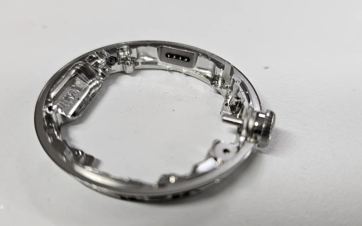
시계 케이스 CNC 가공: MCT 공정 설계와 내부 포켓 정밀가공
GPN ARCHIVE
시계 케이스 CNC 가공MCT 공정 설계와
내부 포켓 정밀가공
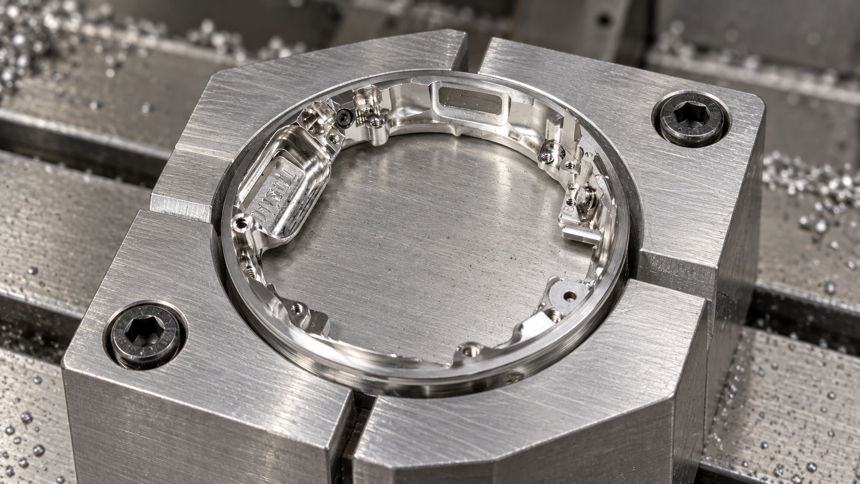
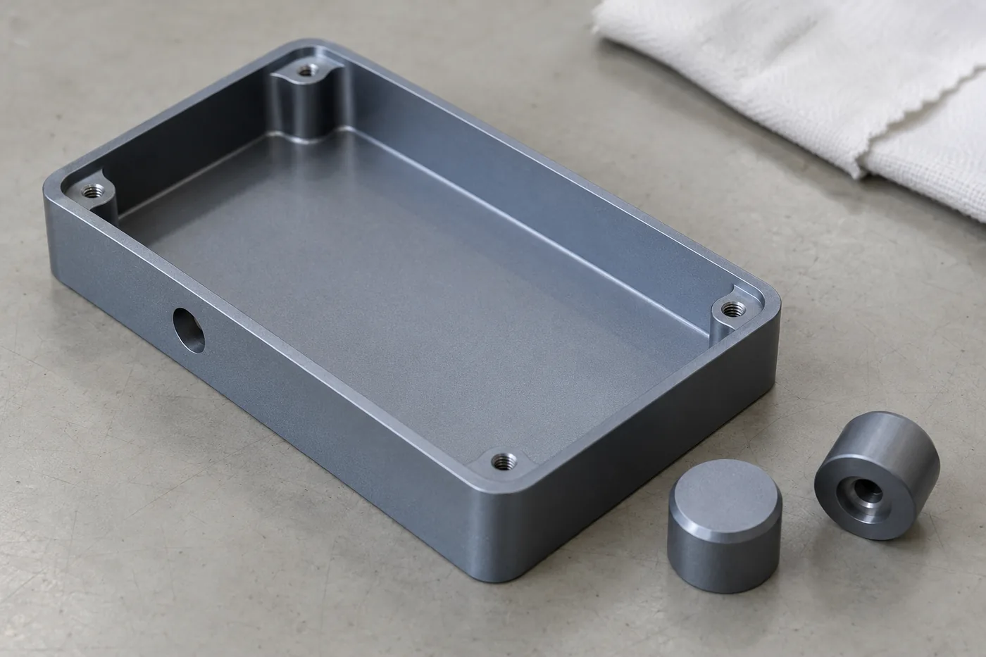
시계 케이스 CNC 가공에서는 넓은 포켓과 좁은 코너, 작은 체결부, 높이가 다른 안착면을 정밀하게 만들어야 합니다. 내부를 깎아낼수록 외벽은 얇아지고 지지는 약해집니다. 황삭에서 남긴 소재와 정삭 순서가 완성된 케이스의 치수와 표면을 좌우합니다.
넓은 공간은 강성이 좋은 공구로 황삭하고, 좁은 코너는 작은 공구로 잔삭합니다. 이어서 벽과 바닥의 여유를 고르게 정리한 뒤 기능면을 정삭합니다. 이 과정에서 어느 부위를 먼저 얇게 만들지, 무엇을 마지막까지 지지로 남길지를 정해야 코너 진동과 벽의 처짐을 줄일 수 있습니다.
01 / 가공 영역
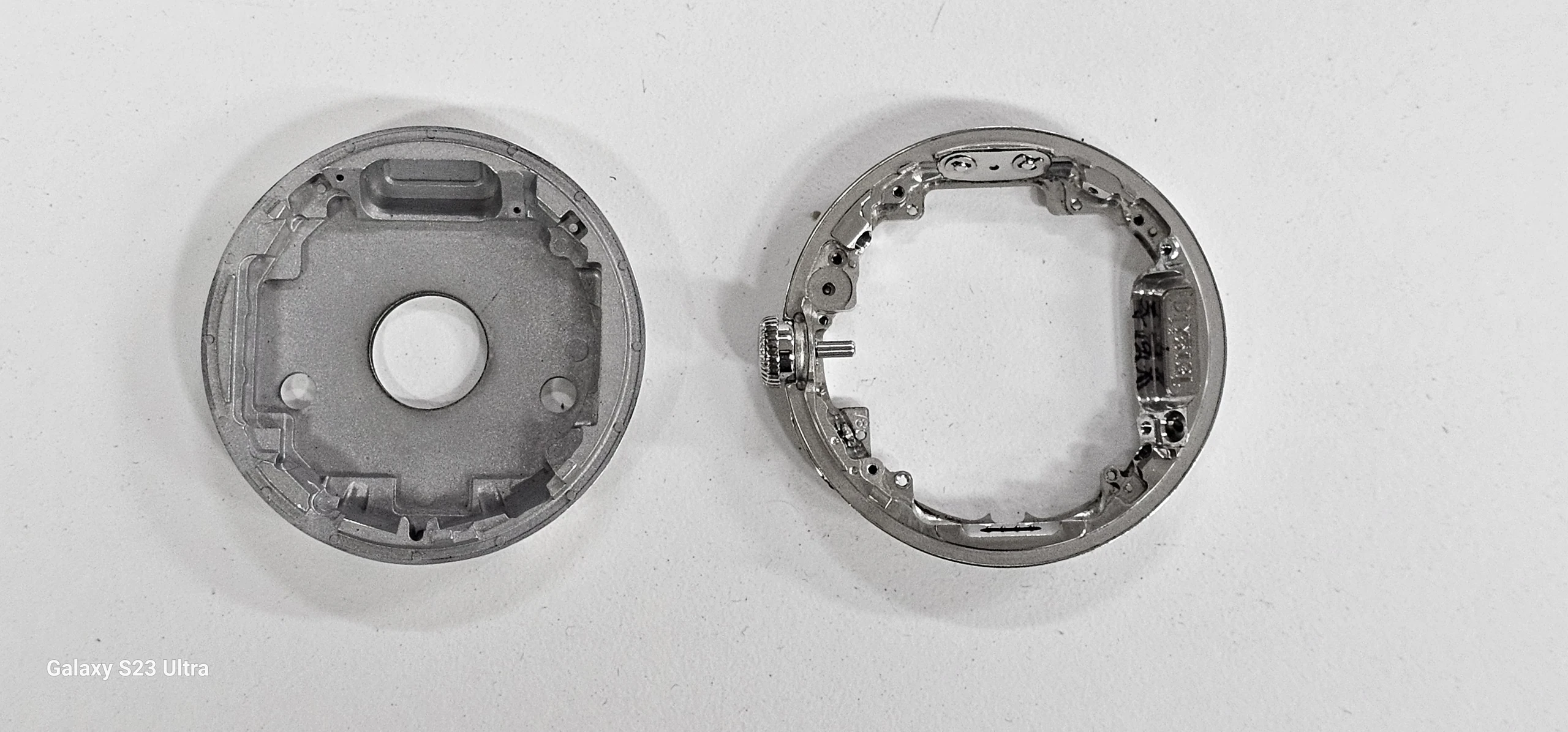
포켓을 가공 영역별로 나누는 기준
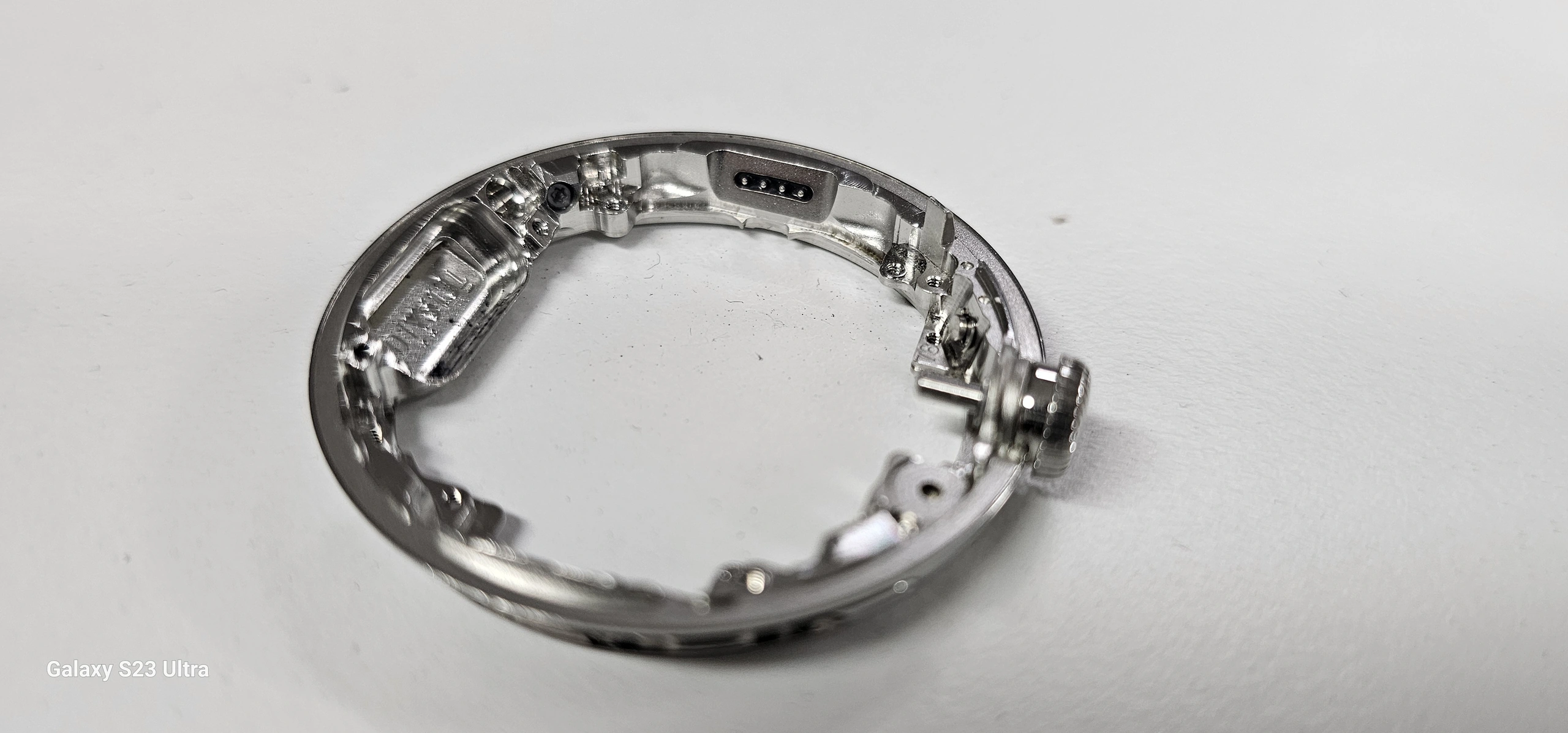
내부 형상을 가공 영역별로 나누면 공구의 역할이 분명해집니다. 넓은 공간에서는 제거 능력이, 좁은 코너에서는 접근성과 공구 강성이 중요합니다. 돌출부 주변과 높이가 다른 바닥은 남는 소재의 지지 역할까지 따져야 합니다.
먼저 도면에서 각 면의 역할을 확인합니다. 부품을 받치는 면은 높이와 평면 상태가 중요하고, 위치를 안내하는 벽은 기준에 대한 위치와 간격이 중요합니다. 단순히 부품이 지나가는 여유 공간은 기능면과 같은 정삭 수준을 요구하지 않을 수 있습니다. 모든 면에 동일한 정삭 패스를 추가하기보다 기능과 공차에 따라 가공 범위를 정합니다.
| 형상 구분 | 가공 계획의 초점 | 확인할 항목 |
|---|---|---|
| 넓은 내부 공간 | 접근 가능한 큰 공구로 주 제거량을 처리합니다. | 진입 공간, 칩 배출, 남길 벽·바닥 여유를 확인합니다. |
| 좁은 코너와 홈 | 앞 공구가 남긴 소재를 작은 공구로 잔삭합니다. | 코너 반경, 순간 물림, 목부와 홀더 간섭을 확인합니다. |
| 단차와 바닥면 | 서로 다른 높이를 분리하고 기능면의 정삭 기준을 정합니다. | 기준면에 대한 높이, 평면 상태, 경계 버를 확인합니다. |
| 남겨지는 돌출부와 얇은 벽 | 주변 소재 제거 순서와 절삭력의 방향을 조정합니다. | 가공 중 지지, 처짐, 고정 해제 후 형상을 확인합니다. |
평면 코너 반경과 바닥 모서리 반경을 구분합니다
위에서 보이는 포켓의 안쪽 코너 반경은 주로 공구 지름과 평면 경로에 관계됩니다. 벽과 바닥이 만나는 모서리의 반경은 공구 끝단 형상과 관계됩니다. 평엔드밀, 코너 래디우스 엔드밀, 볼엔드밀을 같은 목적으로 바꿔 쓰면 바닥 형상이나 모서리 접촉 조건이 달라집니다.
설계 검토에서는 내부 부품의 모서리와 실제로 간섭하는 위치를 확인합니다. 기능상 필요하지 않은 작은 코너나 깊고 좁은 홈은 소경·장축 공구를 요구해 가공 시간을 늘리고 안정성을 낮출 수 있습니다. 형상을 변경할 수 있다면 먼저 조립 간섭과 남는 벽 두께를 검토한 뒤 가공 가능한 반경을 협의합니다.
02 / 공정 설계
시계 케이스 CNC 가공의 기준면과 공정 순서
포켓을 깊게 가공할수록 케이스의 강성이 달라집니다. 앞 공정에서 남긴 바닥이나 두꺼운 연결부가 다음 공정의 지지 역할을 할 수 있으며, 이를 너무 일찍 제거하면 같은 절삭조건에서도 변형과 진동이 커질 수 있습니다. 따라서 황삭·잔삭·정삭을 각각 가장 빠르게 만드는 것만으로 전체 공정이 좋아지지는 않습니다.
아래는 내부 포켓을 가진 케이스를 위한 공정 구성 예시입니다. 소재가 봉재인지, 단조·주조 등으로 형성된 소재인지에 따라 초기 작업은 달라집니다. 실제 공정에서는 형상 접근성, 지그, 후속 가공 부하를 검토해 단계를 묶거나 순서를 조정합니다.
- 기준면과 고정 영역을 확보합니다.
높이·중심·회전 방향을 재현할 기준을 정합니다. 뒤집기나 측면 가공에서 다시 사용할 수 있는지 확인합니다.
- 주 포켓을 황삭합니다.
제거량이 큰 영역부터 처리하되, 얇은 외벽과 돌출부를 지지할 소재를 필요한 시점까지 남깁니다.
- 코너를 잔삭하고 정삭 여유를 고르게 만듭니다.
작은 공구로 남은 소재를 제거합니다. 벽과 바닥의 최종 절삭량이 과도하게 달라지지 않도록 준정삭을 배치합니다.
- 측면·체결 형상과 내부 정삭의 순서를 조율합니다.
측면 구멍의 출구 버, 재고정 부하, 디버링 접근성을 검토합니다. 기능면을 먼저 완성했을 때 뒤 공정이 그 면을 손상시키는지 확인합니다.
- 벽과 바닥을 정삭하고 최종 상태를 검증합니다.
지지 조건에 맞춰 정삭 순서를 정합니다. 디버링·세척과 필요한 후처리 후 도면에 지정된 상태로 검사합니다.
중심 기준만으로 회전 방향까지 정해지지는 않습니다
원형 케이스는 중심을 잡아도 회전할 수 있습니다. 비대칭 포켓과 측면 구멍의 위치 관계를 유지하려면 각도 기준이 필요합니다. 예를 들어 지정된 안착면으로 높이를, 원통면으로 중심을, 별도의 기준 구멍이나 형상으로 방향을 정하는 구성을 검토합니다.
각 공정에서 편하게 잡히는 면을 임의로 원점으로 사용하면, 공정별 치수는 맞아도 형상 사이의 관계가 어긋날 수 있습니다. 기준을 변경해야 할 때에는 기존 기준과 새 기준 사이의 위치 관계를 측정하고, 그 오차가 조립 요구 안에 들어오는지 확인합니다.
지그는 위치 결정과 하중 지지를 나누어 설계합니다
로케이터는 위치를 정하고, 받침은 절삭력과 클램프 힘을 받으며, 클램프는 부품이 그 자리에서 들뜨지 않도록 유지합니다. 얇은 테두리를 강하게 눌러 위치를 맞추면 고정 중에는 치수가 맞다가 해제 후 형상이 바뀔 수 있습니다.
소프트 죠나 형상 지그를 사용할 때에는 접촉 면적뿐 아니라 실제 하중이 전달되는 위치를 확인합니다. 받침 아래의 칩 한 조각도 높이와 기울기를 바꿀 수 있으므로 칩이 빠질 공간과 청소 접근성을 확보합니다. 초기 검증에서는 동일 부품의 고정 상태와 해제 상태를 비교해, 공구 오차와 고정 변형을 구분합니다.
03 / 포켓 황삭
황삭: 진입 경로와 정삭 여유
황삭은 넓은 공간의 소재를 효율적으로 제거하는 단계입니다. 동시에 다음 공구가 갑자기 두꺼운 소재를 만나지 않도록 잔여 형상을 만드는 단계이기도 합니다. 직선 벽에는 얇게 남았지만 코너에 큰 덩어리가 남아 있다면, 같은 정삭 경로에서도 절삭 부하는 크게 달라집니다.
포켓 진입은 공구가 내려갈 공간부터 확인합니다
닫힌 포켓에서는 헬리컬 진입, 경사 진입, 선행 구멍을 통한 진입 등을 비교합니다. 헬리컬 진입은 원을 그리며 내려가기 때문에 진입 구간의 절삭 부하를 분산하는 데 유리할 수 있습니다. 그러나 궤적이 들어갈 폭이 충분해야 하고, 공구가 허용하는 램핑 각도와 피치를 지켜야 합니다.
중심날이 있는 공구라도 모든 깊이에서 수직 절입이 허용되는 것은 아닙니다. 공구의 절입 능력, 바닥 접촉, 칩이 빠져나올 통로를 확인합니다. 공간이 좁아 적절한 진입 경로를 만들 수 없다면 선행 구멍이나 다른 공구 구성을 검토합니다. 이때 선행 구멍의 위치와 깊이도 후속 형상에 영향을 주지 않아야 합니다.
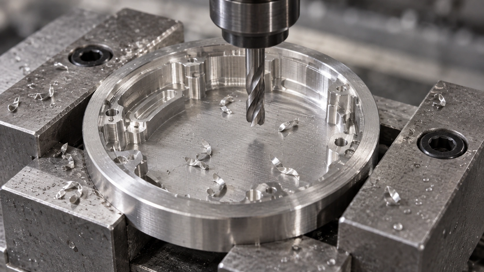
일정한 스텝오버가 일정한 부하를 뜻하지는 않습니다
반경 방향 절삭 폭 ae는 공구가 옆으로 소재를 물고 들어가는 폭이며, 축 방향 절삭 깊이 ap는 공구 축을 따라 한 번에 가공하는 높이입니다. 프로그램에서 옆으로 이동하는 간격이 같아도, 내부 코너나 돌출부 주변에서는 공구가 소재와 접촉하는 각도가 커질 수 있습니다.
적응형 경로나 트로코이달 경로는 공구의 급격한 물림 증가를 줄이는 데 활용할 수 있습니다. 다만 물림을 제어한다고 실제 절삭력이 항상 일정해지는 것은 아닙니다. 재질, 공구 마모, 런아웃, 칩 재절삭, 공작물 강성도 부하를 바꿉니다. 좁은 포켓에서는 경로 자체가 들어갈 공간과 빈 이동 시간까지 비교해야 합니다.
벽 여유와 바닥 여유는 따로 지정합니다
벽에 남기는 반경 방향 여유와 바닥에 남기는 축 방향 여유는 목적이 다릅니다. 벽 여유는 형상 오차와 표면을 정리할 소재를 제공하고, 바닥 여유는 높이 정삭과 가공 중 지지 조건에 관계됩니다. CAM에서 하나의 여유값을 전체 면에 일괄 적용하기 전에 두 방향의 설정을 확인합니다.
여유가 너무 작으면 황삭 때 발생한 처짐이나 표면 손상을 후속 가공에서 제거하지 못할 수 있습니다. 반대로 너무 크면 이미 얇아진 벽을 정삭하는 마지막 공정에 큰 부하가 집중됩니다. 여유량은 도면 공차와 같지 않으며, 황삭 후 실제로 남은 소재와 변형을 확인해 정합니다. 코너에만 많은 소재가 남는다면 정삭 조건을 바꾸기 전에 잔삭이나 준정삭으로 그 차이를 줄입니다.
04 / 잔삭과 코너
잔삭: 코너 부하와 소경 공구
큰 공구는 접근할 수 있는 영역에서 강성과 제거 능력을 확보하기 쉽습니다. 작은 공구는 좁은 코너와 홈에 접근할 수 있지만, 같은 도달 깊이에서 처짐과 파손에 더 민감해질 수 있습니다. 두 공구의 역할을 나누면 작은 공구가 불필요하게 전체 포켓을 반복해서 지나가는 일을 줄일 수 있습니다.
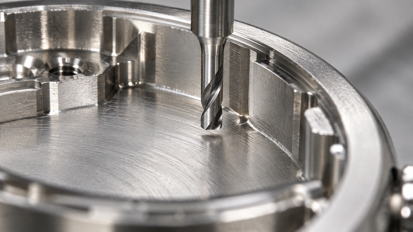
잔삭 경로의 출발점은 최종 모델이 아니라 잔여 소재입니다
잔삭은 앞 공구가 제거하지 못한 부분을 가공하는 작업입니다. 따라서 이전 공구의 지름, 끝단 반경, 가공 깊이와 실제 가공 영역이 경로 계산에 반영되어야 합니다. 최종 형상만 보고 작은 공구의 경로를 만들면 이미 비어 있는 공간을 오래 지나가거나, 예상보다 큰 소재를 갑자기 만날 수 있습니다.
앞 공정의 공구나 깊이를 바꾸었다면 잔삭에 사용하는 소재 모델도 갱신합니다. 여러 고정 방향을 사용하는 경우에는 소재 모델의 좌표와 방향이 다음 세팅에 맞는지 확인합니다. 계산된 잔삭 범위뿐 아니라, 그 범위에 진입하는 순간의 절삭 폭과 공구 아래에 남은 소재도 검토합니다.
공구가 들어가는 것과 안정적으로 코너를 가공하는 것은 다릅니다
평면 내부 코너 반경을 R, 공구 지름을 D라고 하면, 이상적인 기하 조건에서 해당 반경을 만드는 공구는 D ≤ 2R이어야 합니다. 그러나 D가 2R에 가까워질수록 코너에서 공구 중심이 회전하는 반경은 작아집니다. 공구가 코너에 넓게 접촉하고 방향을 급하게 바꾸는 상황을 따로 검토해야 합니다.
내부 코너 R = 1.5 mm를 가정하면 D = 3 mm 공구의 중심 경로 반경은 R − D/2 = 0 mm입니다. D = 2 mm 공구라면 중심 경로 반경은 0.5 mm입니다. 두 번째 조합에는 코너를 돌아갈 경로가 남지만, 그것만으로 절삭 안정성이 보장되지는 않습니다. 이 수치는 관계를 설명하기 위한 예시이며 사진 속 제품의 치수나 권장 공구가 아닙니다.
코너 진동은 공구 지름만 줄여 해결되지 않을 수 있습니다. 앞 공구가 남긴 두꺼운 코너 소재를 여러 경로로 나누어 제거하고, 코너 진입 이전부터 물림 증가를 반영한 이송을 적용합니다. 작은 공구가 곧바로 전폭에 가까운 절삭을 하도록 경로를 만들지 않았는지 확인합니다.
날 길이와 도달 길이를 혼동하지 않습니다
깊은 포켓에 필요한 것은 바닥까지 닿는 도달 길이입니다. 전체 깊이를 한 번에 옆날로 가공하지 않는다면 그만큼 긴 날 길이가 항상 필요한 것은 아닙니다. 짧은 날과 여유 목부를 가진 공구로 높이를 나누어 가공할 수도 있습니다.
반대로 긴 목부가 있다고 전높이 정삭이 가능한 것도 아닙니다. 실제 절삭할 높이는 유효 날 길이 안에 있어야 하며, 목부·생크·홀더가 벽과 간섭하지 않아야 합니다. 공구 도달성은 지름과 전체 길이만으로 판단하지 않고 실제 공구 조립 형상으로 확인합니다.
05 / 벽과 바닥 정삭
정삭: 벽과 바닥의 가공 순서
포켓 벽은 주로 옆으로 밀리는 하중에, 얇은 바닥은 지지 조건에 따라 위아래 방향의 하중에 민감합니다. 벽과 바닥을 같은 패스에서 동시에 마무리하면 서로 다른 방향의 오차를 한 번에 관리해야 합니다. 별도 정삭이 유리한 경우가 많지만, 면을 분리하는 것만으로 가공 순서가 결정되지는 않습니다.
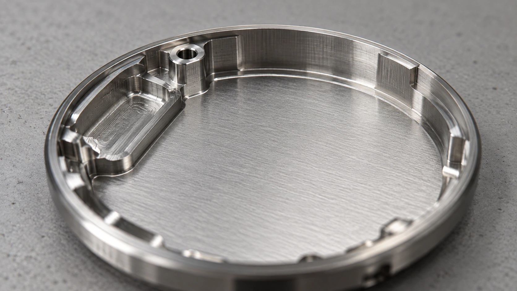
| 가공 중 상태 | 검토할 순서 | 주의할 영향 |
|---|---|---|
| 남은 바닥 소재가 벽을 지지합니다. | 지지용 바닥 여유를 유지한 채 벽을 가공하는 방안을 검토합니다. | 바닥 제거 후 벽 형상이 바뀌는지 확인합니다. |
| 바닥 아래에 안정적인 받침이 있습니다. | 바닥 높이를 먼저 확보한 뒤 벽을 마무리하는 방안을 비교합니다. | 후속 벽 가공의 칩과 경계 절삭이 바닥을 손상시키지 않는지 확인합니다. |
| 벽과 바닥이 모두 얇고 지지가 부족합니다. | 영역·깊이를 나누고 임시 지지 소재나 지그 변경을 검토합니다. | 한 부위를 먼저 최종 두께로 만들 때 전체 강성이 급감하는지 확인합니다. |
순서를 정할 때에는 현재 공정의 표면뿐 아니라 후속 소재 제거로 인한 변형을 평가합니다. 임시 연결부나 지지용 바닥을 남겼다면 그것을 제거하는 마지막 공정과 제거 후 검사까지 작업 경로에 포함해야 합니다.
준정삭은 마지막 한 번의 절삭을 예측 가능하게 만듭니다
황삭 직후에는 위치에 따라 여유량이 다르거나 변형이 발생할 수 있습니다. 준정삭으로 잔여량을 고르게 만들면 정삭 공구가 받는 부하 변화를 줄일 수 있습니다. 다만 준정삭 후에도 부품을 뒤집거나 지그를 바꾸면 상태가 달라지므로, 새 고정 상태에서 여유와 기준을 다시 확인합니다.
동일한 경로를 여유 없이 반복하는 패스가 모든 오차를 없애지는 않습니다. 첫 패스에서 공구나 벽이 밀렸다면 두 번째 패스가 일부 소재를 제거할 수 있지만, 문지름과 시간만 늘어날 수도 있습니다. 반복 패스를 넣기 전에 한 번의 절삭에서 나타나는 오차와 반복 후 변화가 실제로 줄어드는지 측정합니다.
전높이 정삭과 높이를 나누는 정삭을 비교합니다
벽 전체 높이를 한 번에 마무리하면 높이별 패스 경계 흔적을 줄일 수 있습니다. 그러나 날 길이, 공구와 벽의 강성, 진동 안정성이 충분해야 합니다. 작은 반경 방향 절삭 폭을 사용한다고 해서 깊은 축 방향 절삭이 언제나 가능한 것은 아닙니다.
높이를 나누면 한 번에 가공하는 범위를 줄일 수 있지만, 각 높이에서 처짐이 다르면 경계에 단차가 남을 수 있습니다. 경로의 연결과 겹침, 공구 보정, 깊이별 측정 결과를 확인합니다. 선택 기준은 패스 수가 아니라 도면에서 요구하는 벽의 형상과 표면을 반복해서 얻는지 여부입니다.
바닥 정삭은 높이와 면의 흔적을 함께 확인합니다
바닥 높이가 맞더라도 패스 사이의 미세 단차, 공구 진입 흔적, 국부 버가 조립면의 접촉을 방해할 수 있습니다. 공구 끝날 상태, 축 방향 런아웃, 주축과 기준면의 관계, 칩 재절삭을 점검합니다. 기능면에서는 평균 거칠기 수치와 별도로 실제 안착을 방해하는 국부 결함을 확인합니다.
06 / 절삭조건
소경 엔드밀의 절삭조건과 칩 배출
절삭조건은 소재 규격과 경도, 공구 형상·코팅, 돌출 길이, 절삭 폭과 깊이를 확인한 뒤 선정합니다. 동일한 지름의 공구라도 날끝 형상과 유효 날 수가 다르면 같은 조건을 적용하기 어렵습니다. 초기 조건은 공구 제조사의 해당 소재용 데이터를 출발점으로 삼고, 실제 지그와 가공 깊이에서 검증합니다.
회전수와 이송속도 계산 예시
회전수 n = 1,000 × vc ÷ (π × D)
n은 rpm, 절삭속도 vc는 m/min, 공구 지름 D는 mm입니다.
이송속도 vf = n × z × fz
vf는 mm/min, z는 유효 날 수, 날당 이송 fz는 mm/tooth입니다.
D = 2 mm, vc = 60 m/min, z = 2, fz = 0.006 mm/tooth를 가정하면 n은 약 9,549 rpm, vf는 약 115 mm/min입니다. 계산 관계를 보여 주는 가정값으로, 사진 속 케이스에 적용할 절삭조건이 아닙니다. 실제 조건에는 공구 한계, 물림, 소재와 냉각 조건을 반영해야 합니다.
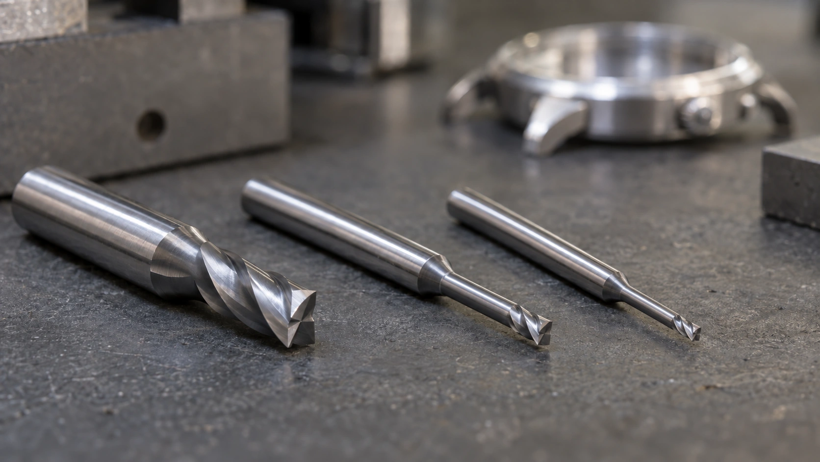
날당 이송을 낮추는 것만으로 표면이 좋아지지는 않습니다
날당 이송은 공구 한 날이 통과할 때 전진하는 거리이며, 실제 칩 두께는 접촉 위치와 물림에 따라 달라집니다. 미세 절삭에서는 칩 두께가 날끝 반경에 비해 매우 작아지면 소재가 제대로 분리되지 않고 눌리거나 문질러지는 비중이 커질 수 있습니다. 이 경우 이송을 더 낮추는 조정이 버와 표면 상태를 악화시킬 수도 있습니다.
런아웃이 있으면 각 날이 같은 양을 절삭하지 않습니다. 특히 날당 이송이 작은 조건에서는 미세한 흔들림도 날별 부하 차이를 크게 만들 수 있습니다. 표면이 나쁘거나 작은 공구가 반복해서 파손된다면 이송값만 변경하지 말고, 공구 체결부의 청결, 홀더 상태, 실제 돌출 위치의 런아웃과 날끝 손상을 확인합니다.
코너 이송은 공구 중심 경로까지 고려합니다
내부 원호를 가공할 때에는 공구 중심이 이동하는 반경과 벽의 반경이 다릅니다. 같은 중심 이송을 유지하면 직선 구간과 접촉점의 이송 관계가 달라질 수 있으며, 코너에서 물림이 증가하는 영향도 더해집니다. CAM의 코너 이송 조정과 제어기의 보정 기능을 확인해 같은 보정을 중복 적용하지 않도록 합니다.
칩 배출도 가공 조건의 일부입니다
좁고 깊은 포켓에 칩이 남으면 이미 잘린 칩을 다시 절삭해 표면을 긁거나 순간 부하를 높일 수 있습니다. 절삭유나 에어가 실제 가공점과 바닥까지 도달하는지, 지그가 배출 통로를 막지 않는지 확인합니다. 냉각·윤활 방식은 소재와 공구의 권장 조건에 맞춰 선택하고, 도달성이 나쁘다면 노즐 위치와 가공 순서를 함께 조정합니다.
07 / 검증과 측정
CAM 검증부터 최종 치수 검사까지
CAM에서 경로가 매끄럽게 보이더라도 실제 가공이 검증된 것은 아닙니다. 첫째, 실제 소재와 중간 공정 형상을 사용해 과절삭·잔여 소재·진입 물림을 확인합니다. 둘째, 공구뿐 아니라 목부·생크·홀더와 지그의 간섭을 확인합니다. 셋째, 적용 가능한 기계 시뮬레이션과 검증 절차로 회전축, 이동 한계, 포스트 처리된 동작을 확인합니다.
일반적인 소재 제거 시뮬레이션은 공구가 지나간 기하 형상을 계산합니다. 공구 처짐, 얇은 벽의 탄성 변형, 소재의 잔류응력 해소까지 자동으로 보증하지는 않습니다. 경로 검증 이후의 초도 가공과 측정은 이러한 실제 오차를 확인하는 과정입니다.
CAM 공차를 제품 공차로 해석하지 않습니다
경로 계산 공차는 모델과 계산 경로 사이의 기하 근사 수준에 관계됩니다. 제품 치수에는 공구 지름 오차, 런아웃, 기계 운동 오차, 온도, 고정과 절삭 변형도 영향을 줍니다. 스무딩을 사용하는 경우에는 형상 근사에 추가로 허용되는 편차까지 확인해 전체 오차 예산 안에 배분합니다.
| 검사 시점 | 확인할 대상 | 다음 공정의 판단 |
|---|---|---|
| 세팅·재고정 직후 | 기준면 안착, 중심과 방향, 공구 기준을 확인합니다. | 가공 원점과 기준 관계가 재현되는지 판단합니다. |
| 황삭·잔삭 후 | 벽과 바닥의 잔여량, 코너의 남은 소재, 변형을 확인합니다. | 준정삭·정삭으로 목표 형상을 만들 여유가 있는지 판단합니다. |
| 정삭 후 | 벽의 높이별 위치, 단차 높이, 바닥 상태와 코너를 확인합니다. | 형상 오차와 국부 표면 결함을 구분합니다. |
| 고정 해제·마감 후 | 도면에 지정된 지지 상태에서 기능 치수, 버와 청정도를 확인합니다. | 완성 상태의 안착·간섭·체결 요구를 만족하는지 판단합니다. |
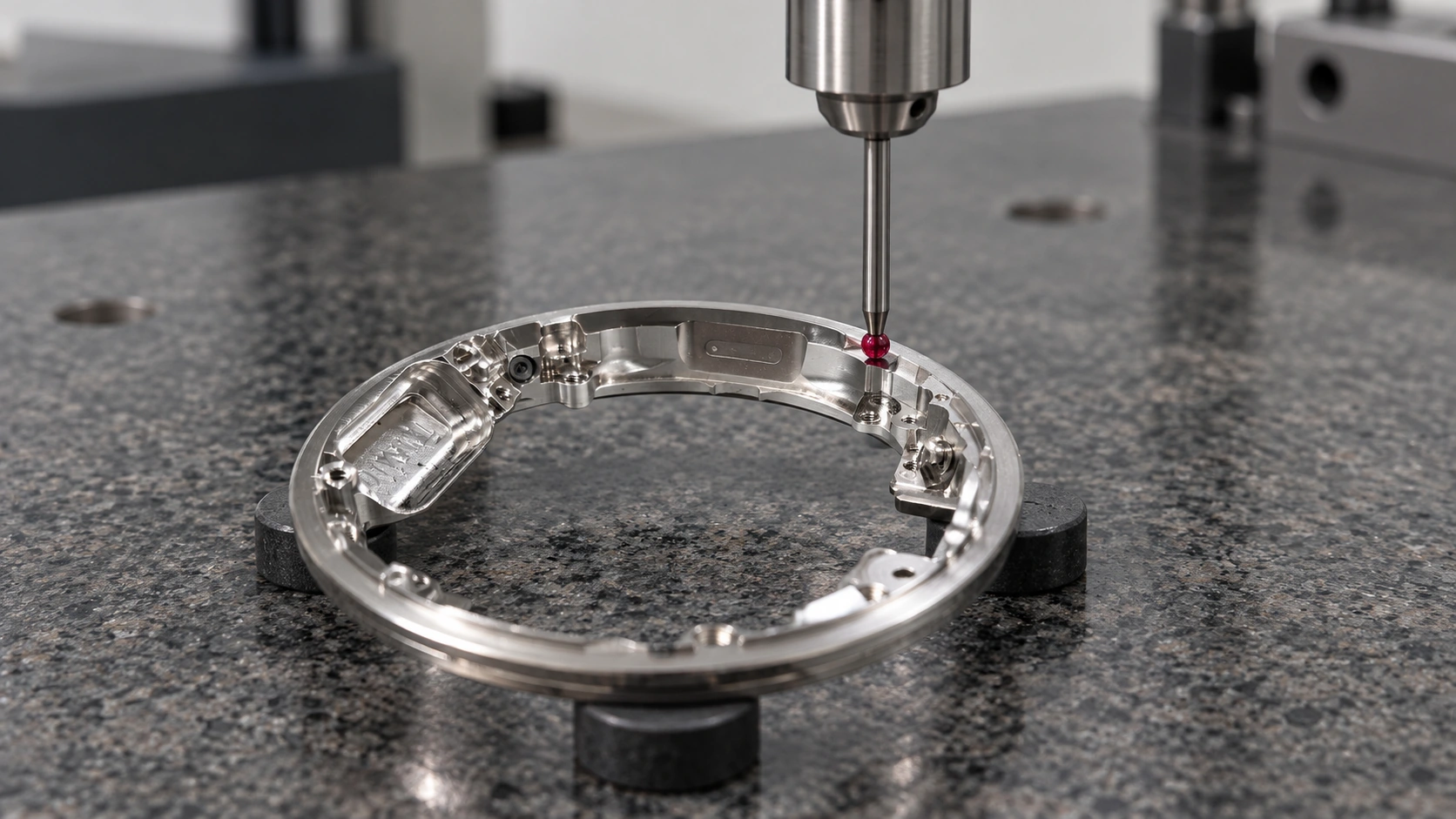
기계 안에서의 프로빙은 세팅 오차와 공정 변화를 빨리 찾는 데 유용합니다. 다만 고정 상태의 측정값과 자유 상태의 형상은 다를 수 있습니다. 얇은 부품은 측정력이나 받침 위치로도 변형될 수 있으므로, 최종 판정에는 도면과 검사 규격에 지정된 지지 조건을 재현합니다. 측정 방법은 접근성, 반사 특성, 공차와 필요한 측정 불확도를 고려해 선택합니다.
버 제거와 마감 이후의 상태를 판정합니다
측면 구멍이 내부 포켓으로 관통하는 곳이나 단차 경계에는 버가 남을 수 있습니다. 버를 제거할 접근 방향과 허용 모서리 형상을 미리 정하면 기능면을 과도하게 깎는 일을 줄일 수 있습니다. 연마가 필요한 면은 제거량이 치수에 미치는 영향을 확인하고, 안착면이나 끼워맞춤면의 보호 범위를 정합니다.
세척 후에는 작은 포켓과 구멍에 칩이나 연마재가 남지 않았는지 확인합니다. 최종 조립에서는 부품이 충분히 안착하는지, 국부 간섭이 없는지, 체결과 측면 작동부가 요구 조건을 만족하는지 검증합니다. 포켓의 가공 완료와 제품의 기능 검증은 이 단계에서 연결됩니다.
08 / 원인 진단
가공 흔적으로 찾는 오차 원인
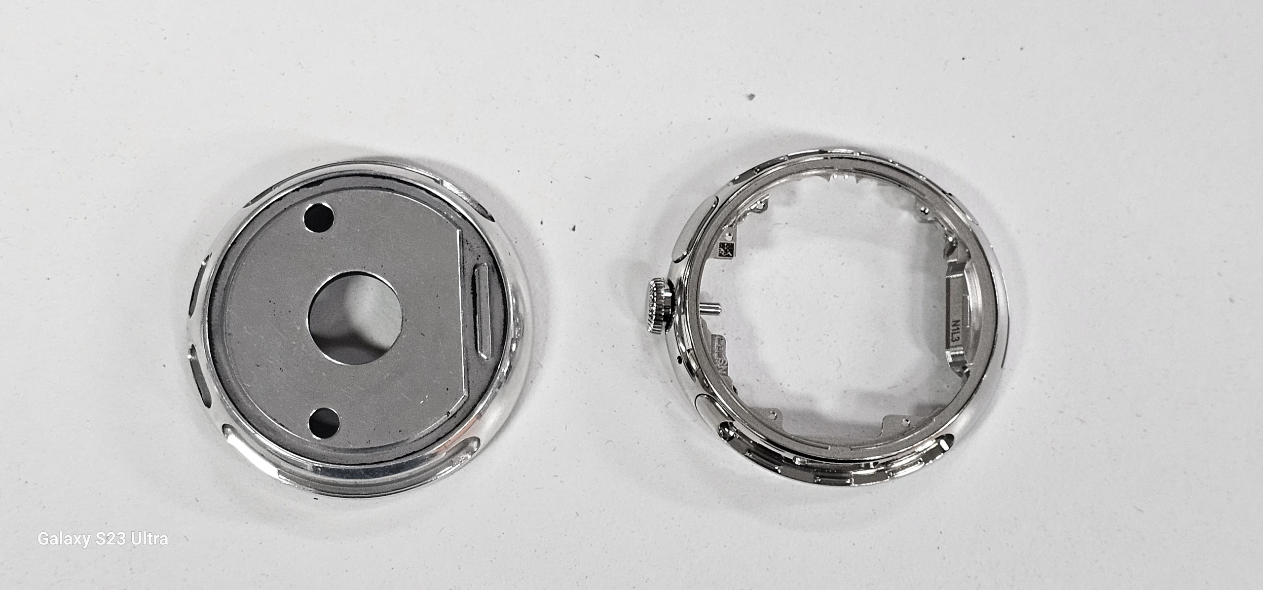
진동이나 치수 오차가 생겼을 때 모든 이송을 낮추거나 모든 공구 보정을 바꾸면 원인을 구분하기 어렵습니다. 직선과 코너, 벽의 위·아래, 고정 중과 해제 후를 나누어 비교하면 어느 단계에서 문제가 시작되는지 판단하기 쉽습니다.
| 나타나는 현상 | 우선 확인할 원인 | 검증과 조정 방향 |
|---|---|---|
| 직선은 양호하지만 코너에서 진동합니다. | 코너 잔여량과 순간 물림 증가, 경로 반경을 확인합니다. | 잔삭으로 부하를 나누고 코너 진입 경로·이송을 검증합니다. |
| 벽의 위·아래 치수가 다릅니다. | 공구와 벽의 처짐, 공구 상태와 기계 기하 오차를 확인합니다. | 여러 높이에서 측정하고 돌출·지지·정삭 깊이를 조정해 비교합니다. |
| 바닥에 패스 경계 단차가 남습니다. | 끝날 상태, 축 방향 런아웃, 주축 기울기와 높이 설정을 확인합니다. | 공구 조립 상태와 바닥 경로를 점검한 뒤 표면·높이를 함께 측정합니다. |
| 코너나 단차 주변에 소재가 남습니다. | 잔삭에 사용한 이전 공구 정보, 깊이·경계·여유 설정을 확인합니다. | 실제 이전 공정의 소재 모델로 경로를 다시 계산하고 비교합니다. |
| 지그 해제 후 치수가 달라집니다. | 클램프 변형과 소재 제거에 따른 변형을 구분합니다. | 고정 전후·공정 전후 측정을 나누고 지지와 제거 순서를 검토합니다. |
변경 효과는 같은 측정 조건에서 비교합니다. 예를 들어 코너만 불안정하다면 전체 이송을 바꾸기 전에 그 구간의 잔여량과 물림을 확인합니다. 해제 후 형상만 달라진다면 공구 지름 보정보다 고정과 공정 순서의 영향을 먼저 분리합니다.
시계 케이스의 공정은 황삭에서 지지를 남기고, 잔삭에서 국부 부하를 정리하며, 정삭에서 기능면을 완성하고, 최종 검사에서 그 관계를 확인하는 흐름으로 설계합니다. 이 연결이 명확해야 공구·CAM·지그의 개선이 실제 조립 품질과 반복성으로 이어집니다.
ENGLISH EDITION
CNC machining of watch cases
Process planning and precision machining of internal pockets
Machining the interior of a watch case means removing substantial material while preserving thin walls, tight corners and seating features at different heights. Planning must therefore address both the cutter path and the material that remains to support subsequent operations.
Use a rigid cutter for bulk pocket removal and a smaller cutter for residual corners. Equalize the remaining allowance before finishing the functional walls and floors. Decide which regions may become thin early and which material must remain as support; these choices influence corner vibration, wall deflection and final geometry.
01. Divide the interior into distinct machining regions
Separating the interior into machining regions makes tool selection more precise. Broad cavities favor efficient removal; narrow corners require access and stiffness from smaller cutters. Retained bosses, islands and floors at different elevations require separate consideration of how the remaining material supports the cut.
Assign functions before selecting paths. A seating face is governed by its height and form; a locating wall by its position and clearance relative to the specified datums. A clearance cavity may not require the finish or accuracy of a mating surface. Allocate finishing operations according to function and tolerance instead of applying the same treatment everywhere.
| Region | Planning priority | Check |
|---|---|---|
| Main cavity | Use a larger tool where access permits efficient bulk removal. | Entry space, chip evacuation, and retained wall and floor stock. |
| Narrow corners and slots | Use a smaller tool to remove stock left by the previous cutter. | Corner radius, transient engagement, and neck and holder clearance. |
| Steps and floors | Separate elevations and establish finishing references for functional faces. | Height relative to the datum, surface form and edge burrs. |
| Retained islands and thin walls | Plan surrounding removal and cutting-force direction. | Support during machining, deflection and released geometry. |
Distinguish the internal corner radius seen in plan view from the fillet where a wall meets a floor. The former relates to cutter diameter and the planar path; the latter relates to the cutter’s end geometry. A square, corner-radius or ball-end tool does not produce the same floor and transition geometry.
Where design changes are possible, identify the exact contact or interference that requires a tight corner. An unnecessarily small radius or deep narrow slot may force a smaller, less rigid tool. Review mating clearance and remaining wall thickness before agreeing a more machinable feature.
02. Plan the intermediate workpiece, not only the final shape
Pocketing changes the workpiece’s stiffness. A thick floor or connecting region can support the next cut; removing it early can increase deformation or vibration even when cutting parameters remain unchanged. Optimizing roughing, rest machining and finishing independently can therefore undermine the complete route.
The following sequence is a planning example. Initial operations differ for bar stock and preformed blanks, including forged or cast material. Combine or reorder stages according to access, fixturing and the loads imposed by later operations.
- Establish datums and holding regions.
Define repeatable height, center and angular orientation, including references needed after reversal or side machining.
- Rough the main pockets.
Remove bulk material while retaining support around thin walls and local features for as long as needed.
- Rest-machine corners and equalize finishing stock.
Remove residual regions with smaller tools and use semi-finishing where necessary to make the final cut more consistent.
- Coordinate side features with internal finishing.
Account for exit burrs, reclamping loads and deburring access. Check whether later operations could damage completed functional surfaces.
- Finish walls and floors, then verify the completed condition.
Select the order against the available support. Inspect after deburring, cleaning and any required finishing, under the drawing-defined condition.
Datums and fixture support
A circular locating surface establishes a center but does not establish angular orientation. Asymmetric pockets and side holes need a repeatable rotational reference. A possible arrangement uses a specified plane for height, a cylindrical feature for centering, and a separate hole or feature for orientation.
Changing to whichever surface is easiest to locate in each operation can preserve individual dimensions while losing their relationship. Where datum transfer is necessary, measure the relationship between the old and new references and assess its contribution to the assembly requirement.
Separate the roles of locators, supports and clamps. Locators establish position, supports react loads, and clamps maintain seating. Forcing a thin ring into location with excessive pressure can produce acceptable measurements while clamped and a different shape after release.
For soft jaws or a contoured nest, evaluate the actual load path as well as contact area. Trapped chips can change height or tilt, so include relief and cleaning access. During initial qualification, compare the same part clamped and released to distinguish workholding distortion from cutting error.
03. Rough the pocket with the next cutter in mind
Roughing removes bulk material and creates the stock condition inherited by the following operation. A thin allowance on a straight wall and a large residual mass in a corner expose a finishing cutter to very different loads along an otherwise continuous path.
For closed pockets, compare helical entry, linear ramping and entry through a prepared hole. Helical entry can distribute the entry cut, but the pocket must accommodate the required orbit. Respect the cutter’s permitted ramp angle, pitch and end-cutting capability.
A center-cutting tool is not automatically suitable for unrestricted vertical plunging. Consider end engagement and a viable chip exit path. If the pocket cannot accommodate a suitable entry, evaluate a prepared hole or a different tool arrangement, including the effect of the hole’s location and depth on subsequent geometry.
Engagement and finishing allowance
Radial engagement, ae, describes the width engaged across the cutter; axial depth, ap, describes the cutting height along its axis. Equal programmed stepovers do not guarantee equal engagement. Contact can increase substantially around an internal corner or island.
Adaptive and trochoidal paths can reduce abrupt engagement changes. They do not guarantee constant cutting force: material, wear, runout, chip recutting and workpiece stiffness also contribute. In a small cavity, compare the space required by the path and the resulting noncutting travel as well as material-removal capability.
Set radial wall stock and axial floor stock separately where their purposes differ. Wall stock provides material for correcting form and finish. Floor stock relates to final height and may contribute support during intermediate operations.
Insufficient allowance may leave no material to remove roughing error or surface damage. Excessive allowance can concentrate heavy cutting in the final operation, when the structure is already thin. Allowance is not the same as drawing tolerance: establish it using the actual remaining stock and distortion after roughing. Address thick corner residues through rest machining or semi-finishing before expecting a uniform finishing pass.
04. Concentrate small tools on residual corners and narrow features
A larger cutter can offer useful stiffness and removal capacity where it fits. A smaller cutter reaches tighter details but may be more sensitive to deflection and breakage at the same depth. Assigning distinct roles avoids repeatedly machining the entire cavity with its smallest required tool.
Rest machining must use an accurate representation of what the previous operation left behind. Previous cutter diameter, end radius, depth and machined region all matter. A path based only on the finished model may include excessive air cutting or unexpected heavy engagement.
If an earlier cutter or machining depth changes, update the stock used for subsequent rest machining. With multiple setups, verify the stock model’s coordinate relationship to the new orientation. Examine entry engagement and remaining material below the cutter, not just the highlighted residual region.
Corner radius and cutter access
For an ideal planar internal corner of radius R and a cutter of diameter D, the geometric requirement is D ≤ 2R. As D approaches 2R, however, the cutter-center turning radius approaches zero. Geometric access alone does not establish stable cutting.
For an assumed internal radius R = 1.5 mm, a D = 3 mm cutter gives a center-path radius of R − D/2 = 0 mm. With D = 2 mm, the center-path radius is 0.5 mm. The second combination leaves room for a curved center path, but does not guarantee acceptable engagement or stability. These are explanatory dimensions, not specifications or tooling recommendations for the photographed cases.
A smaller tool alone may not resolve corner vibration. Divide heavy residual corner stock into controlled cuts and adjust the entry path and feed before engagement rises. Check that the small cutter is not unexpectedly entering a nearly full-width cut.
Reach and cutting length
Distinguish reach from flute length. A deep pocket requires sufficient reach, but does not always require a cutting edge as long as the complete depth if the wall is machined in levels. A short-flute, relieved-neck tool may provide access for that strategy.
Conversely, a long neck does not make a tool suitable for full-height wall finishing. The engaged height must fit within the effective cutting length, and the neck, shank and holder must clear the wall. Validate the assembled tool geometry rather than relying only on diameter and overall length.
05. Select wall and floor finishing order from the support condition
Thin walls are sensitive to lateral loading; thin floors can respond strongly to axial loading depending on support. Finishing both simultaneously couples different error mechanisms. Separate passes can help, but separation alone does not determine which surface should be finished first.
| Intermediate condition | Sequence to evaluate | Subsequent effect to check |
|---|---|---|
| Retained floor stock supports the wall. | Evaluate wall machining while retaining the supporting floor allowance. | Whether removing the floor stock changes the completed wall. |
| The floor has stable support below it. | Compare establishing the floor height before final wall machining. | Whether later chips or boundary cuts damage the floor. |
| Both walls and floor are thin and poorly supported. | Evaluate staged regions or depths, temporary support stock or a different fixture. | Whether completing one region causes a sharp loss of overall stiffness. |
Evaluate distortion from later removal, not just the surface produced by the current cut. If temporary connecting material or a supporting web is retained, include its eventual removal and the subsequent inspection in the route.
Uniform stock before the final pass
Semi-finishing can equalize stock before the final pass. Roughing may leave uneven allowances and distortion, making finishing load unpredictable. If the workpiece is reversed or reclamped after semi-finishing, recheck the references and available stock in the new holding condition.
Repeating a nominally zero-stock path is not a universal correction. A repeat pass may remove material left by elastic deflection, but it may also add rubbing and cycle time. Measure the first-pass error and the change after repetition before making that pass part of the production route.
Full-height and staged finishing
Full-height wall finishing can reduce witness lines between depth levels, but requires adequate cutting length, tool and workpiece stiffness, and dynamic stability. Low radial engagement does not automatically make a large axial depth safe or accurate.
Dividing the wall into levels reduces the engaged height, but different deflection at each level can leave steps. Review transitions, overlap, compensation and measurements at multiple heights. Choose the method that repeatedly satisfies the required form and finish, rather than the one with the fewest passes.
For floors, verify both height and local surface condition. Pass boundaries, entry marks and burrs can prevent seating even when nominal depth is correct. Investigate end-edge condition, axial runout, spindle alignment relative to the reference plane and chip recutting. Average roughness alone does not describe every local defect affecting contact.
06. Select speed and feed together with material, tooling and engagement
Confirm material grade and hardness, cutter geometry and coating, overhang, cutting width and depth before selecting parameters. Tools with the same diameter can have different edge geometry and effective tooth counts. Begin with toolmaker data for the relevant material, then validate the conditions at the actual reach and workholding arrangement.
Example: calculating spindle speed and feed rate
n = 1,000 × vc / (π × D)
Spindle speed n is in rpm, cutting speed vc in m/min, and cutter diameter D in mm.
vf = n × z × fz
Feed rate vf is in mm/min, z is the effective tooth count, and feed per tooth fz is in mm/tooth.
Assume D = 2 mm, vc = 60 m/min, z = 2 and fz = 0.006 mm/tooth. The results are approximately 9,549 rpm and 115 mm/min. These assumptions demonstrate the calculation; they are not cutting settings for the photographed cases. Actual settings must account for tool limits, engagement, material and cooling.
Chip thickness, runout and corner feed
Feed per tooth is the advance associated with each tooth passing the cut. Actual chip thickness changes with position and engagement. In micro-milling, when chip thickness becomes very small relative to the edge radius, deformation and rubbing can become significant instead of effective chip formation. Further feed reduction may therefore worsen burr formation or surface condition.
Runout makes the teeth remove unequal amounts of material. Its relative effect can be substantial at small feeds per tooth. If finish is poor or small tools repeatedly fail, inspect interface cleanliness, holder condition, runout at the actual working extension and edge damage before adjusting feed alone.
During an internal circular move, the cutter center travels at a different radius from the machined wall. The relationship between programmed center feed and feed at contact changes from a straight cut, while increased corner engagement adds another load effect. Check CAM and controller compensation to avoid applying the same feed correction twice.
Coolant delivery and chip removal
Chip evacuation belongs in parameter planning. Chips retained in a deep narrow pocket can be recut, scratch the surface and produce transient overload. Confirm that coolant or air reaches the cutting region and floor, and that the fixture does not obstruct the exit path. Choose cooling and lubrication to suit the material and cutter; where delivery is poor, adjust nozzle placement and the machining sequence together.
07. Separate CAM verification from dimensional acceptance
A smooth-looking animation does not verify the complete machining process. First, use realistic initial and intermediate stock to check gouging, remaining material and entry engagement. Second, verify the neck, shank and holder against the workpiece and fixture. Third, use applicable machine simulation and verification procedures to assess rotary motion, travel limits and postprocessed movements.
Conventional material-removal simulation evaluates geometry swept by the cutter. It does not automatically establish tool deflection, thin-wall elastic response or distortion from residual stress redistribution. First-off machining and measurement are needed to reveal these physical effects.
Geometric verification and part tolerance
Toolpath tolerance relates to geometric approximation between the model and calculated path. Finished-part error also includes tool diameter error, runout, machine motion, temperature, workholding and cutting deformation. If smoothing is applied, include its permitted geometric deviation in the total error budget. Do not treat a CAM tolerance setting as a guaranteed part tolerance.
| Inspection stage | What to inspect | Decision supported |
|---|---|---|
| Setup and reclamping | Datum seating, center, orientation and tool references. | Whether the required reference relationships have been reproduced. |
| After roughing and rest machining | Wall and floor stock, corner residues and distortion. | Whether enough suitable stock remains for semi-finishing and finishing. |
| After finishing cuts | Wall position at several heights, step heights, floors and corners. | Whether errors concern overall form or local surface defects. |
| After release and final processing | Functional dimensions, burrs and cleanliness under the specified support condition. | Whether the completed part meets seating, clearance and fastening requirements. |
Inspection after machining and release
On-machine probing helps detect setup error and process drift, but clamped measurements may differ from released geometry. Measuring force and support position can themselves deform a thin part. Reproduce the support condition specified by the drawing and inspection procedure, and select the method against access, optical reflections, tolerance and required uncertainty.
Plan access to burrs where side holes break into pockets or where steps meet. Define allowable edge geometry so that deburring does not remove excessive material from functional faces. For polished regions, evaluate dimensional removal and protect seating or mating surfaces as required.
After cleaning, check small pockets and holes for chips and polishing residue. Assembly verification should establish full seating, absence of local interference, suitable fastening, and the required operation of side features. This connects pocket machining to the function of the completed component.
08. Use the location and timing of an error to narrow the cause
Reducing every feed or changing all tool offsets makes diagnosis difficult. Compare straight sections with corners, the top and bottom of walls, and clamped with released geometry to identify where the error begins.
| Observed symptom | Investigate first | Verification and adjustment |
|---|---|---|
| Straight walls are acceptable; corners vibrate. | Residual corner stock, transient engagement and path radius. | Divide the residual cut and verify corner entry and feed. |
| Wall size differs with height. | Tool or wall deflection, tool condition and machine geometry. | Measure at several heights; compare changes to overhang, support and axial depth. |
| Steps remain between floor passes. | End-edge condition, axial runout, spindle alignment and height settings. | Check the tool assembly and floor path, then measure both surface and height. |
| Stock remains around corners or steps. | Previous-tool information, depth, boundaries and allowance settings. | Recalculate against the actual preceding stock state and compare the result. |
| Dimensions change after unclamping. | Clamping distortion versus material-removal effects. | Separate before/after clamping from before/after machining comparisons. |
Compare changes under consistent measurement conditions. If only corners are unstable, inspect their stock and engagement before slowing the complete program. If geometry changes mainly on release, separate fixture and sequencing effects before relying on cutter-diameter compensation.
The complete route retains support during roughing, controls local stock through rest machining, establishes functional surfaces during finishing, and verifies their relationships in final inspection. Keeping these stages connected allows improvements in tooling, CAM and fixturing to translate into repeatable assembly quality.
추가 정보
주제 요약
시계 케이스의 CNC·MCT 가공에서는 전체 공정 순서와 내부 포켓 경로를 함께 설계합니다. 공정 중 남는 소재의 지지 역할, 공구별 잔여량, 벽과 바닥의 정삭 조건을 연결해 최종 기능면의 형상과 위치 관계를 확보합니다.
핵심 포인트
- 내부 공간을 넓은 포켓, 좁은 코너, 단차, 얇은 벽으로 나누어 공구와 품질 기준을 정합니다.
- 높이·중심·회전 방향의 기준을 공정 사이에 유지하고, 고정 중 변형과 해제 후 형상을 구분합니다.
- 큰 공구로 주 제거량을 처리한 뒤 실제 잔여 소재를 기준으로 작은 공구의 잔삭 경로를 계산합니다.
- 벽·바닥 여유를 구분하고 지지 조건에 맞춰 정삭 순서를 결정합니다.
- CAM 검증, 중간 측정, 마감 후 검사와 조립 검증을 서로 연결합니다.
FAQ
작은 엔드밀 하나로 전체 포켓을 가공하면 안 됩니까?
형상과 조건에 따라 가능할 수 있습니다. 다만 작은 공구가 필요하지 않은 넓은 영역까지 같은 공구로 처리하면 가공 시간과 공구 부담이 커질 수 있습니다. 공구 교환 시간까지 포함해 큰 공구의 황삭과 작은 공구의 잔삭을 조합한 방식을 비교합니다.
벽과 바닥 중 어느 쪽을 먼저 정삭해야 합니까?
남은 바닥이 벽을 지지하는지, 바닥 아래에 받침이 있는지, 후속 절삭이 완성면에 어떤 영향을 주는지에 따라 달라집니다. 한 가지 순서를 모든 케이스에 적용하지 않고, 공정별 변형과 최종 측정으로 확인합니다.
정삭 여유는 얼마를 남겨야 합니까?
소재, 공구, 벽 두께, 황삭 오차, 고정 조건을 확인해야 정할 수 있습니다. 벽과 바닥의 여유를 구분하고, 부족한 영역과 코너의 과도한 잔여량이 없는지 중간 측정과 소재 모델로 확인합니다.
코너에서 진동하면 회전수와 이송을 모두 낮춰야 합니까?
먼저 코너의 잔여량, 순간 물림과 공구 중심 경로를 확인합니다. 국부 부하가 원인이라면 잔삭 단계나 진입 경로를 바꾸는 조정이 필요할 수 있습니다. 소경 공구에서는 지나치게 낮은 날당 이송이 문지름을 늘릴 수 있어 조건을 따로 검증합니다.
사진 속 부품에는 반드시 5축 장비가 필요합니까?
사진만으로 결정할 수 없습니다. 필요한 접근 방향, 홀더 간섭, 재고정 오차, 공차와 생산 수량을 비교해야 합니다. 3축 장비와 지그로 가능한 형상도 있고, 여러 방향을 한 번의 고정에서 처리하는 방식이 유리한 경우도 있습니다.
CAM 시뮬레이션에서 문제가 없으면 치수도 보장됩니까?
소재 제거와 간섭 검증만으로 공구 처짐, 고정 변형, 온도와 기계 오차까지 보장할 수는 없습니다. 초도 가공과 중간 검사, 지정된 지지 상태에서의 최종 측정이 필요합니다.
관련 주제
박벽 부품의 공정 순서 · 정밀 지그와 기준 전달 · 적응형 포켓 황삭 · 잔삭 소재 모델 · 소경 엔드밀 런아웃 · 정삭 여유와 공차 관리 · 미세 버 제거 · 가공 중 측정
내부 링크
관련 키워드
시계 케이스 CNC · MCT 공정 설계 · 내부 포켓 가공 · 포켓 황삭 · 코너 잔삭 · 정삭 여유 · 박벽 정삭 · 소경 엔드밀 · 공구 런아웃 · CAM 시뮬레이션 · 지그 설계 · 정밀가공 검사

Related posts

명품 무브먼트 마감: 앵글라주·블랙 폴리싱·제네바 스트라이프의 정밀 제조
3축 가공과 5축 가공: 공구 접근·셋업·정밀도와 제조 원가 비교
외장 SSD 케이스: 알루미늄 방열 구조와 정밀가공 설계

세라믹 베젤링: 스테인리스 결합 구조와 열팽창·충격 설계
알루미늄 외장 아노다이징 색차: 소재·표면·피막에서 조립 색상까지