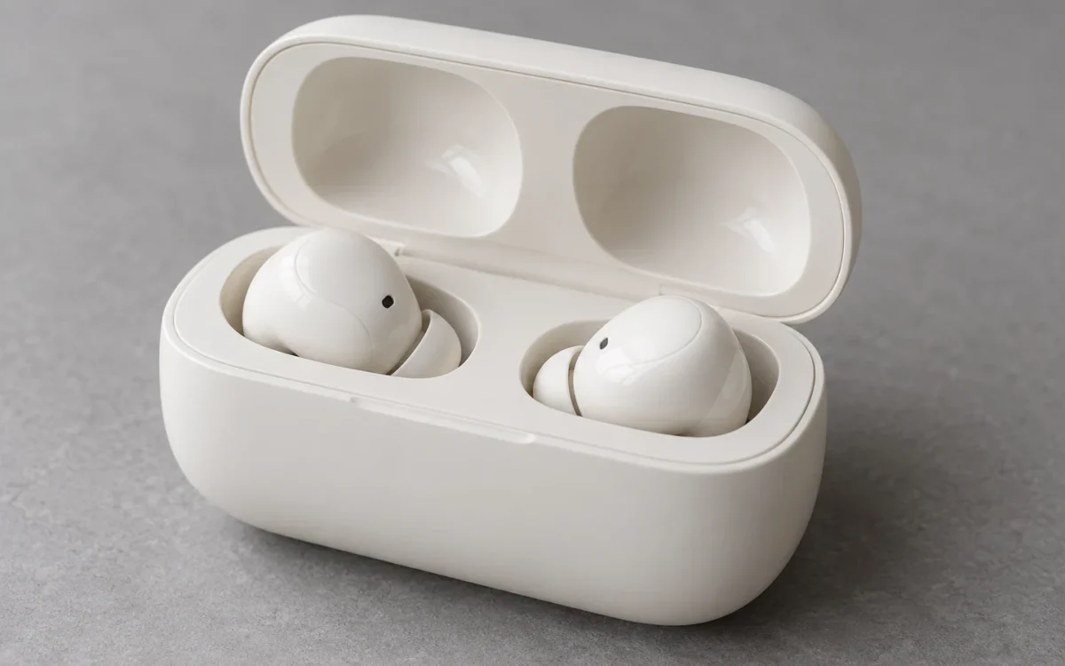
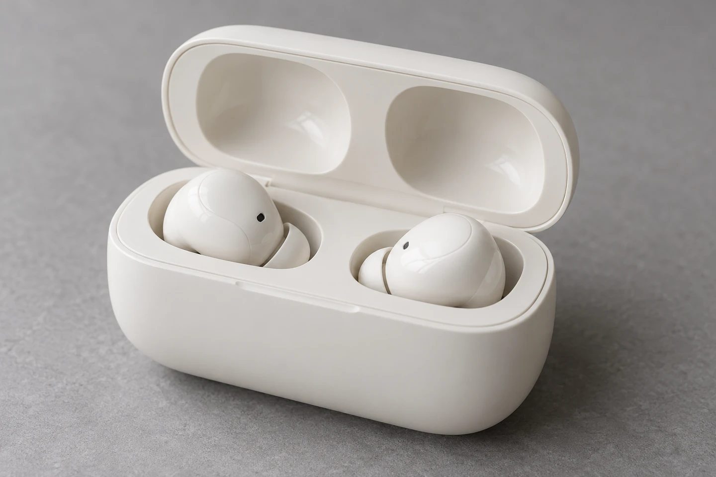
이어폰 충전케이스 힌지: 플라스틱 내부 장착과 MIM 정밀부품 설계
이어폰 충전케이스 힌지: 플라스틱 내부 장착과 MIM 정밀부품 설계
이어폰 충전케이스의 내장형 힌지는 플라스틱 외피와 내부 라이너 사이의 좁은 공간에 자리합니다. 작은 금속 브래킷과 핀이 회전축을 만들고, 내부 장착부가 뚜껑의 하중을 케이스로 전달합니다. 외관의 매끈한 연결을 유지하면서 개폐 공간·고정 강성·회전 간극을 함께 확보해야 합니다.
충전케이스 힌지는 금속 부품과 플라스틱 장착부를 하나의 기구로 설계해야 합니다. 금속 모듈은 케이스 뒤쪽 포켓에 수납하고 내부 트레이·라이너로 가립니다. 뚜껑에 연결되는 작은 암에는 회전할 공간이 필요하며, 핀을 붙잡는 고정부와 자유롭게 회전하는 구멍의 기능도 구분합니다. 금속 핀홀만 정밀해도 내부 장착부가 움직이면 뚜껑 끝에는 흔들림과 닫힘 단차가 나타날 수 있습니다.
MIM은 작은 브래킷에 지지암·보강 리브·고정 형상을 함께 만드는 공정으로 검토할 수 있습니다. 다만 회전축의 기능을 맡는 구멍과 끝면까지 성형만으로 완성해야 하는 것은 아닙니다. 필요한 부분에 정밀가공을 배분하고, 금속 부품과 케이스를 조립한 상태에서 개폐 품질을 확인하는 접근이 중요합니다.
1. 플라스틱 내부에 수납하는 충전케이스 힌지 구조
내장형 힌지는 본체의 뒤쪽 내부 장착면에 고정되는 브래킷, 뚜껑 안쪽에 연결되는 회전부, 두 부품을 잇는 핀으로 구성할 수 있습니다. 외피는 외관을 형성하고, 내부 프레임이나 트레이의 포켓·리브·보스가 금속 부품의 위치를 잡습니다. 외피와 내부 프레임을 분리하는지, 외피 자체에 장착부를 만드는지는 제품 구조에 따라 달라집니다.
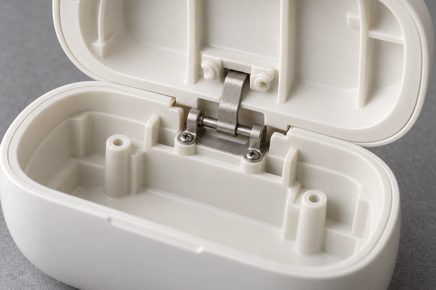
완성품에서는 내부 라이너와 뒤쪽 커버가 힌지 모듈을 가립니다. 반면 내부 트레이와 뚜껑 라이너를 조립하기 전에는 금속 브래킷과 연결 암이 보입니다. 이때 필요한 것은 금속을 수지로 빈틈없이 채우는 구조가 아니라, 고정부는 안정적으로 지지하고 회전부에는 움직일 여유를 남기는 구조입니다.
개폐 경로와 내부 공간의 동시 설계
회전축을 깊숙이 숨기는 것만으로 내장형 힌지가 완성되지는 않습니다. 축의 위치에 따라 뚜껑 뒤쪽 모서리가 본체 벽에 먼저 부딪히거나, 연결 암이 내부 트레이를 긁을 수 있습니다. 뒤쪽의 작은 개구와 커버 형상은 뚜껑의 전체 회전 경로에 맞춰 정합니다.
닫힘·중간 각도·최대 개방에서 연결 암과 외피, 내부 트레이, 스토퍼의 간섭을 검토합니다. 스프링·캠·댐퍼를 채택한다면 작동 중 차지하는 공간까지 포함합니다. 배터리·기판·충전 코일의 배치와는 기계적인 여유 공간을 조율하고, 전기·무선 성능은 별도의 제품 검증으로 확인합니다.
회전 안내와 뚜껑 유지력의 분리
회전축은 뚜껑이 정해진 경로를 따라 움직이도록 안내합니다. 뚜껑을 열린 위치에 유지하거나 닫힘 직전에 당기는 기능은 별도의 스프링·캠·자석 등이 담당할 수 있습니다. 따라서 구멍을 무조건 작게 만들어 마찰을 높이는 방법으로 개폐감을 조정하면, 조립력과 마모까지 함께 변하게 됩니다.
| 기능 | 설계 대상 | 제조·조립에서 확인할 관계 |
|---|---|---|
| 회전 경로 안내 | 핀과 회전부 핀홀입니다. | 지름 간극, 구멍 형상, 유효 접촉 길이와 축 정렬을 확인합니다. |
| 핀 이탈 방지 | 고정부 끼워맞춤, 머리·끝단 또는 별도 유지 구조입니다. | 핀 유지력과 조립 후 지지암 변형을 함께 확인합니다. |
| 케이스 내부 고정 | 장착 포켓, 안착면, 리브·보스와 체결부입니다. | 회전축 위치, 하중 전달 면적과 조립 후 수지 변형을 확인합니다. |
| 개폐 저항·위치 유지 | 마찰부, 토션스프링, 캠 또는 자석입니다. | 열림과 닫힘 각각의 토크–각도 관계를 확인합니다. |
| 개방 끝단 정지 | 스토퍼와 하중을 받는 연결부입니다. | 반복 충돌과 과개방 하중이 전달되는 경로를 확인합니다. |
토크가 큰 힌지가 항상 유격도 작은 것은 아닙니다. 스프링이 뚜껑을 강하게 밀어도 횡방향 핀홀 간극이 남을 수 있습니다. 반대로 유격이 작은 회전축도 별도의 유지 구조가 없으면 자유롭게 움직입니다. 도면과 검사 항목에서도 두 성능을 구분해야 원인을 정확히 찾을 수 있습니다.
2. 핀의 미세 간극이 뚜껑 끝에서 커지는 이유
회전부 구멍의 지름을 D, 핀 지름을 d라고 하면 직경 간극 C는 D−d입니다. 축이 구멍 중심에 있을 때 한쪽 반경 간극은 C/2입니다. 직경 간극과 반경 간극을 혼용하면 계산값과 검사 결과가 두 배 차이 날 수 있습니다.
C = D − d / c = C ÷ 2
D: 회전부 핀홀 지름 · d: 핀 지름 · C: 직경 간극 · c: 중심 일치 상태의 한쪽 반경 간극입니다.
핀 지름과 홀 지름을 각각 공차로 관리할 때는 평균값보다 조합의 끝값을 먼저 봅니다. 최소 간극은 Dmin−dmax, 최대 간극은 Dmax−dmin입니다. 최소값에서는 회전 여유를, 최대값에서는 흔들림을 검토합니다. 버·도금·진원도·조립 변형은 이 지름 계산과 별도로 남습니다.
회전부의 길이와 관찰 위치
짧은 원통 구멍은 같은 직경 간극에서도 핀에 대해 더 많이 기울 수 있습니다. 회전부 구멍의 유효 접촉 길이를 L, 축에서 뚜껑 끝의 관찰점까지 거리를 R로 두면, 작은 각도의 강체 모델에서 한쪽 최대 기울기를 θ≈C/L로 근사할 수 있습니다. 이 기울기에 의한 관찰점의 한쪽 변위는 δ≈R·C/L입니다.
여기서 L은 회전하는 구멍 내부에서 실제로 지지에 참여하는 길이입니다. 고정 브래킷의 외측 지지암 간격을 그대로 대입하는 값이 아닙니다. 모따기가 길거나 접촉이 한쪽에 집중되면 외형상 배럴 길이와 유효 접촉 길이가 달라질 수 있습니다.
간극과 접촉 길이에 따른 뚜껑 끝 변위
가정 계산 · R = 20 mm · δ ≈ R × C / L · L은 회전부 유효 접촉 길이입니다.
강체·작은 각도·양 끝의 반대쪽 접촉을 가정한 편측 기울기 성분입니다. 반전되는 전체 기울기 폭은 2δ이며, 병진 간극·탄성 변형·축 방향 이동을 포함한 실제 총 유격은 아닙니다.
예를 들어 R=20 mm, L=4 mm, C=0.02 mm를 가정하면 한쪽 기울기 변위는 약 0.10 mm입니다. 반대 방향 끝 접촉까지 움직이는 기울기 성분의 전체 폭은 약 0.20 mm가 됩니다. 이 값은 원리를 비교하기 위한 계산이며, 실제 충전케이스의 측정값이나 허용 유격이 아닙니다.
실제 뚜껑에서는 핀과 구멍의 병진 이동, 핀 굽힘, 브래킷 변형, 케이스 체결부의 변형이 함께 나타납니다. 축 방향으로 움직이는 끝면 간극도 별도입니다. 따라서 계산 그래프를 완제품의 총 유격으로 사용하지 않고, 간극과 지지 길이 중 무엇을 조정할지 판단하는 데 활용합니다.
3. 수지 내부 장착부와 금속 핀홀의 기준 연결
뚜껑 하중을 받는 포켓·리브·보스
내부 트레이와 뚜껑 라이너를 덮기 전에는 후방 포켓의 브래킷 고정면과 연결부를 확인할 수 있습니다. 나사로 체결하는 구조라면 보스는 체결 위치를 제공하고, 안착면과 주변 리브는 금속 모듈을 지지합니다. 접착·열가압 리벳팅·인서트 성형 등 다른 고정 방식을 선택할 때도 하중을 받는 면과 회전을 허용하는 영역을 구분해야 합니다.
뚜껑을 열거나 과도하게 젖히는 힘은 뚜껑 내부 연결부, 금속 회전축과 브래킷, 장착면·체결부를 거쳐 수지 케이스로 전달됩니다. 얇은 외관 벽이나 작은 보스 끝에만 힘이 집중되면 금속 힌지가 손상되기 전에 수지가 변형될 수 있습니다. 장착면을 넓히고 적절한 리브로 지지하되, 사출 두께가 급격히 두꺼워져 수축과 외관 함몰이 생기지 않도록 함께 검토합니다.
수지에 일정 하중이 오래 작용하면 변형이 증가하는 크리프가 나타날 수 있으며, 체결부에서는 응력완화로 예압이 달라질 수 있습니다. 금속 인서트가 있어도 주변 수지의 변형까지 없어지는 것은 아닙니다. 재질·온도·시간·하중 조건에 따라 회전축 위치와 닫힘 라인의 변화를 평가합니다.
외피부터 뚜껑 닫힘 라인까지의 공차 누적
내부 포켓의 위치, 브래킷 안착 높이, 핀축 위치, 뚜껑 연결부의 고정 위치가 차례로 닫힘 단차에 영향을 줍니다. 두 체결점을 억지로 맞추어 조이면 브래킷이나 수지 프레임이 휘어, 금속 단품 검사에서는 없었던 축 오차가 생길 수 있습니다. 위치를 결정하는 기준과 조립 여유를 허용할 방향을 나누고, 실제 체결 후 형상을 확인합니다.
핀홀의 공통축과 기능 기준면
작은 핀을 여러 구멍에 통과시키는 구조에서는 각 구멍의 지름이 합격해도 조립이 뻑뻑할 수 있습니다. 두 고정 지지부의 구멍축이 어긋나거나, 중앙 회전부의 구멍이 기울어져 있으면 핀이 한쪽 가장자리를 누르게 됩니다. 단품의 지름 측정만으로 이러한 관계를 확인할 수 없습니다.
우선 케이스에 실제로 닿는 장착면을 기준으로 잡고, 위치를 결정하는 측면이나 기준 형상을 연결합니다. 이 기준에서 회전축의 위치와 방향, 두 지지부 핀홀의 공통축 관계, 축 방향 끝면의 위치를 지정합니다. 측정하기 편한 외관면이 조립 기준과 다르면 검사 합격품에서도 조립 편차가 발생할 수 있습니다.
| 관리 대상 | 기능과 연결되는 이유 | 공정에서의 판단 |
|---|---|---|
| 두 지지부 핀홀의 축 관계 | 핀의 삽입 경로와 편심 접촉을 좌우합니다. | 가능하면 공통 기준과 연결된 세팅에서 가공하고, 재세팅 오차를 포함해 검토합니다. |
| 회전부 구멍의 원통 형상 | 입구 지름이 같아도 테이퍼·타원·국부 돌출에 따라 접촉이 달라집니다. | 입구 한 단면의 영상 측정만으로 전체 구멍을 판정하지 않습니다. |
| 배럴 끝면과 축 방향 간극 | 뚜껑의 좌우 이동과 끝면 마찰에 영향을 줍니다. | 폭 치수, 끝면 방향, 조립 후 지지암 간격을 함께 봅니다. |
| 핀의 직진도·표면 | 구멍을 통과하는 기능과 국부 마모에 영향을 줍니다. | 지름뿐 아니라 휨, 끝단 버, 표면 손상을 관리합니다. |
리머는 구멍의 크기와 표면을 정리하는 데 유용하지만, 이미 크게 어긋난 선행 구멍의 축을 자동으로 바로잡는 공정은 아닙니다. 선행 홀의 위치, 공구 진입, 남겨 둔 가공 여유와 부품 지지가 함께 맞아야 합니다. 부품이 작을수록 공구보다 먼저 얇은 지지암이 밀리는 문제도 확인합니다.
핀 입구의 모따기는 조립을 돕지만, 회전부 전체를 큰 모따기로 처리하면 유효 지지 길이가 줄어듭니다. 외관을 부드럽게 만드는 연마 공정도 홀 입구와 끝면을 동시에 둥글게 만들 수 있으므로 기능면과 외관면의 마감 범위를 구분합니다.
4. MIM 힌지 브래킷과 정밀 후가공의 역할
충전케이스 힌지의 고정 브래킷은 두 지지암, 얇은 연결부, 수지와 결합하는 형상 등이 한 부품에 모일 수 있습니다. 이러한 입체 형상에서는 MIM을 통해 부품 수와 조립 접점을 줄이는 방안을 검토할 수 있습니다. 반면 형상이 단순하고 생산 수량이 작다면 절삭가공이나 프레스·굽힘 구조가 더 적합할 수도 있습니다.
금속 브래킷을 만드는 MIM과 플라스틱 외피·내부 프레임을 만드는 사출 공정은 구분합니다. 먼저 만든 금속 부품을 수지 성형 때 삽입하는 인서트 성형은 가능한 결합 방식 중 하나입니다. 이 방식을 선택하더라도 회전 핀홀이나 움직이는 연결부에 수지가 유입되지 않도록 기능 영역을 보호해야 합니다.
성형할 형상과 가공할 기능면
MIM의 장점은 복잡한 형상을 일체화하는 데 있습니다. 회전부의 엄격한 구멍 공차까지 모든 면에 동일하게 요구하면 금형·소결·선별 비용이 함께 커집니다. 외곽과 보강 구조는 성형으로 확보하고, 회전 핀홀·장착 기준면·축 방향 접촉면에 필요한 후가공을 배분하는 방식이 실무적으로 중요합니다.
관통 홀을 금형 코어로 만들 수 있는지는 홀의 방향, 길이, 코어 강성, 이형 방식에 따라 달라집니다. 성형 홀을 선행 형상으로 남겨 후가공할 수도 있고, 후가공으로 홀을 완성할 수도 있습니다. “MIM이면 작은 구멍을 모두 완성할 수 있다”거나 “핀홀은 반드시 전량 절삭해야 한다”는 식의 일괄 판단은 적절하지 않습니다.
형상 성형에서 케이스 내부 조립까지
형상·기준 설계
내부 포켓·회전 공간
기준면과 가공 여유
MIM 성형
지지암·보강부 일체화
코어와 금형 분할 검토
탈지·소결
수축·뒤틀림 관리
기능면 위치 확인
기능면 가공
핀홀·끝면·장착면
공통 기준으로 연결
표면·세정
기능면 처리 범위
최종 치수·버 확인
내부 장착·검증
모듈 조립·수지 고정
라이너 전후 개폐 비교
핀은 요구 공차와 유지 형상에 맞춰 별도로 제작합니다. 금속 모듈과 수지 부품은 각 공정을 거쳐 조립하며, 라이너를 덮은 완성 상태에서 개폐 간섭과 유격을 확인합니다.
작은 지지암의 소결 변형과 가공 고정
서로 마주 보는 지지암은 소결 후 벌어지거나 비틀릴 수 있습니다. 두꺼운 연결부와 얇은 팔의 두께 변화, 성형 충전, 탈지 경로와 소결 지지 상태를 함께 검토해야 합니다. 소결 치수만 보정해도 모든 캐비티와 위치의 형상 편차가 같은 방향으로 줄어드는 것은 아닙니다.
후가공 지그가 지지암을 강제로 모아 놓은 상태에서 홀을 가공하면, 지그를 풀었을 때 축 관계가 달라질 수 있습니다. 장착 기준면을 안정적으로 지지하고 가공력이 얇은 부분에 집중되지 않도록 해야 합니다. 핀 삽입 시에도 받침 위치가 멀면 압입력이 지지암의 굽힘 하중으로 바뀝니다.
핀은 브래킷과 별도로 봉재·선재를 기반으로 제작할 수 있습니다. 요구되는 지름, 직진도, 끝단 형상과 생산량에 따라 절삭·연삭·성형 공정을 선택합니다. 고정부의 유지 형상과 회전 구간의 표면을 구분하면, 회전 구간을 손상시키지 않고 조립하는 방법을 마련하기 쉬워집니다. 관련 형상은 MIM 부품 제조와 정밀 선반가공의 공정 범위를 함께 검토할 수 있습니다.
5. 반복 개폐에서 달라지는 마찰·마모·표면 상태
힌지는 한 방향으로 계속 도는 축과 달리 정지와 방향 전환을 반복합니다. 회전 범위가 좁으면 접촉 하중이 특정 구간에 집중되고, 윤활제가 충분히 재분포하지 못하는 조건도 생깁니다. 초기 개폐 토크가 부드럽다는 사실만으로 장기 마모가 작다고 판단할 수 없습니다.
재질은 핀과 상대 구멍을 한 쌍으로 선정
스테인리스라는 재질명만으로 마찰과 내마모 성능을 정할 수 없습니다. 경도·열처리 상태·접촉 압력·표면 거칠기와 상대 재질이 함께 작용합니다. 같은 계열 금속의 접촉에서는 응착이나 긁힘이 문제될 수 있으며, 내식성이 좋다는 사실이 무윤활 회전 성능을 보장하지는 않습니다.
핀의 경도를 높이면 상대 구멍의 마모가 지배적이 될 수도 있습니다. 표면을 경화하거나 코팅할 때도 구멍과 핀 중 어느 면이 변형을 받아 주는지, 박리된 입자가 어디로 이동하는지를 확인해야 합니다. MIM 부품의 잔류 기공과 표면 상태는 실제 소결·후가공 조건에서 평가하며, 함유 기공을 근거로 자동적인 자기윤활 효과를 주장하지 않습니다.
표면처리 두께를 포함한 최종 간극
핀과 구멍 양쪽의 원래 표면 밖으로 막이 쌓이면 핀은 굵어지고 구멍은 작아집니다. 핀의 한쪽 치수 증가량을 tp, 홀 내면의 한쪽 치수 감소량을 th라고 두고 균일한 막을 가정하면, 최종 직경 간극은 다음과 같이 정리할 수 있습니다. 여기서 t는 치수를 바꾸는 유효 막 두께이며, 산화·확산을 포함하는 모든 표면처리의 전체 막 두께와 같은 뜻은 아닙니다.
Cfinal = Cbefore − 2(tp + th)
예를 들어 초기 직경 간극 20 µm에 핀과 홀 각각 2 µm의 균일한 막이 생기면 계산상 최종 간극은 12 µm입니다. 실제 막의 분포·거칠기·마스킹 경계와 공정 편차는 별도로 반영합니다.
이 관계 때문에 표면처리 전 핀홀 검사만으로 최종 조립성을 승인하면 안 됩니다. 작은 깊은 구멍에서는 내면에 같은 두께의 막이 형성된다고 가정하기 어렵습니다. 도금·코팅을 적용할 면과 제외할 면, 최종 검사 시점을 도면과 공정표에 연결해야 합니다.
윤활제와 수지·전자부품의 적합성
윤활은 마찰과 소음을 줄이는 수단이지만 종류와 도포량을 함께 관리해야 합니다. 점도가 달라지면 저온의 개폐감이 변할 수 있고, 과다 도포하면 주변으로 번져 접착부나 접점을 오염시킬 수 있습니다. 수지의 응력 균열, 외관 얼룩, 윤활제의 이동 가능성도 완성 조립체에서 확인합니다.
마모를 단순식으로 추정할 때 사용하는 마모계수는 재질명만으로 확정되는 상수가 아닙니다. 실제 접촉·윤활·오염 조건에서 얻은 데이터가 없으면 목표 개폐 횟수를 계산으로 보장할 수 없습니다. 반복 시험의 중간 시점에서 유격과 토크를 함께 추적해야 초기 길들이기와 지속적인 열화를 구분할 수 있습니다.
6. 완성된 충전케이스 힌지의 조립·검증
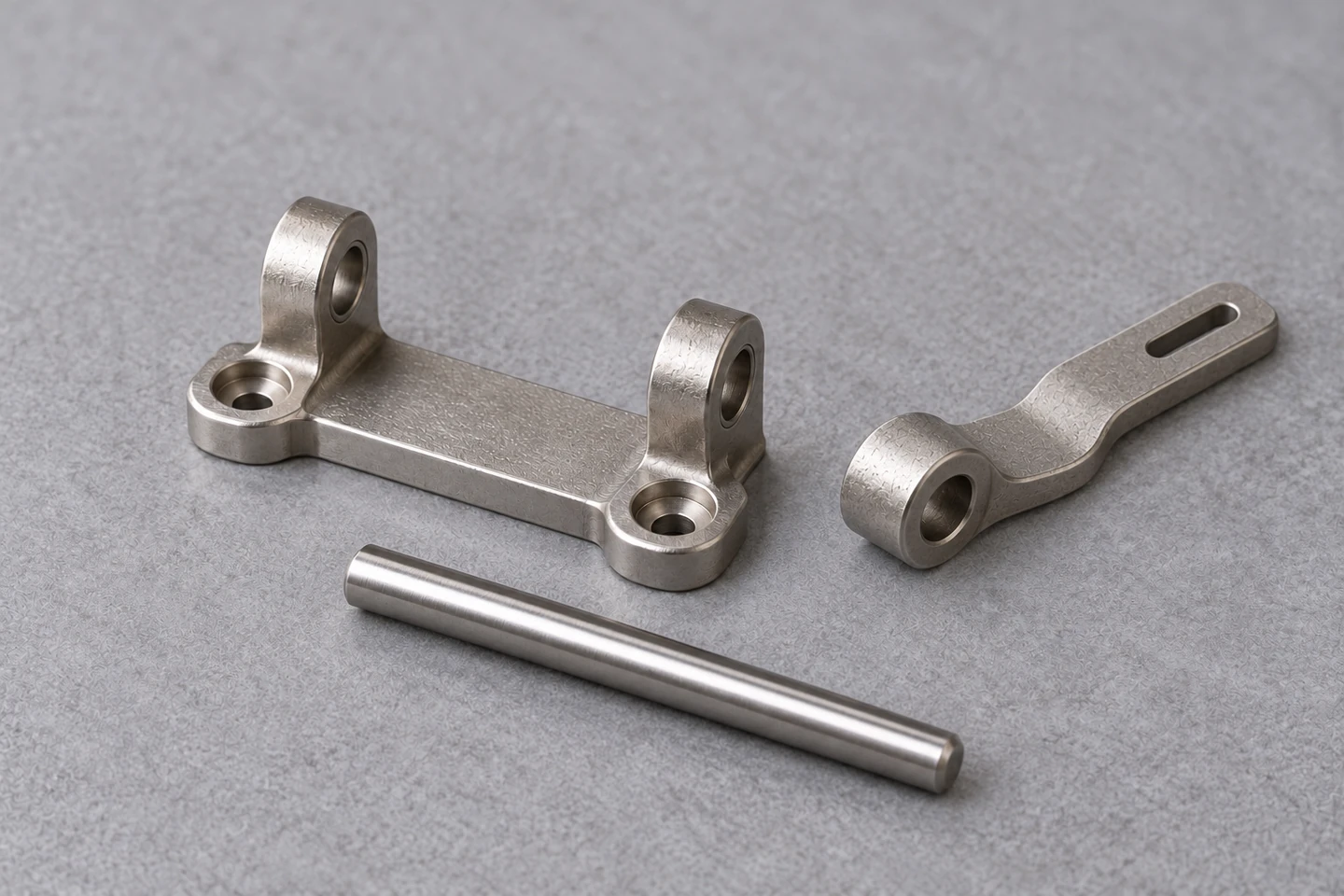
핀 삽입 공간과 라이너 조립 순서
완성 외피 안에서는 핀을 옆으로 밀어 넣거나 체결 공구를 접근시키기 어려울 수 있습니다. 금속 브래킷·회전부·핀을 먼저 모듈로 조립한 뒤 내부 포켓에 넣는 방법과, 부품을 케이스 안에 배치한 뒤 핀을 삽입하는 방법을 구분해 검토합니다. 실제 핀 유지 방식과 조립 접근성에 따라 순서를 정합니다.
모듈을 장착한 후에는 라이너를 덮기 전에 회전 상태와 고정 위치를 확인합니다. 이어서 라이너·트레이를 조립한 상태에서 개폐 토크와 뚜껑 단차를 다시 비교합니다. 조립 공간이 확보되어도 회전 공간이 부족할 수 있으며, 라이너를 덮은 뒤에만 나타나는 마찰은 핀홀보다 주변 수지의 간섭을 먼저 확인해야 합니다.
금속 부품의 기능면 검사
작은 홀은 광학 측정으로 입구 형상과 위치를 확인하기 좋지만, 표면에서 보이는 원 하나가 내부 전체의 원통도를 뜻하지는 않습니다. 기능 게이지, 접촉식 측정, 단면 관찰 등은 구멍의 크기와 접근성에 맞게 선택합니다. 측정기 분해능만으로 합격을 정하지 않고 고정·초점·조명·측정 반복성까지 포함합니다.
핀 삽입력은 홀 상태와 정렬 이상을 찾는 공정 신호가 될 수 있습니다. 그러나 삽입력이 높다고 유지력이나 조립 강도가 반드시 좋은 것은 아닙니다. 버 또는 축 어긋남 때문에 힘이 증가했을 수도 있으므로, 삽입 하중 변화와 조립 후 회전 상태를 함께 확인합니다.
개폐 토크와 유격의 측정 조건
개폐 토크는 열림·닫힘 각도, 속도, 주변 온도와 측정 시작 상태를 정해 비교합니다. 손으로 일정 위치를 밀어 측정한 힘 F를 토크로 환산할 때는 힘의 작용선에 수직인 모멘트암 r⊥를 사용해 T=F·r⊥로 계산합니다. 뚜껑이 회전하면서 이 거리가 변하면 같은 힘도 같은 토크가 아닙니다.
유격은 뚜껑의 열림 각도를 고정하고, 같은 관찰점에 같은 크기의 반대 방향 하중을 주어 비교합니다. 측정 위치가 힌지에 가까운지 뚜껑 끝인지, 금속 힌지 단품인지 케이스 조립체인지 기록해야 합니다. 하중을 크게 주면 탄성 변형이 포함되므로 “손으로 흔들었을 때 움직인 양”만으로 부품 간극을 확정하지 않습니다.
| 확인 단계 | 보는 항목 | 비교 조건 |
|---|---|---|
| 금속 부품 상태 | 핀·홀 지름, 축 정렬, 끝면 간격과 표면입니다. | 가공·표면처리 완료 상태와 기능 기준면을 지정합니다. |
| 힌지 조립 직후 | 삽입 상태, 회전 저항, 축 방향 이동과 핀 유지입니다. | 누르는 방향과 지지 위치를 일정하게 관리합니다. |
| 케이스 결합 후 | 체결 변형, 닫힘 단차, 뚜껑 끝 흔들림과 내부 간섭입니다. | 실제 고정 공정을 적용하고 라이너 조립 전후를 비교합니다. |
| 반복 개폐 이후 | 토크 변화, 유격 증가, 마모분과 소음입니다. | 개폐 각도·속도·횟수·정지 시간·환경과 판정 시점을 정합니다. |
| 환경·충격 이후 | 수지 백화·균열, 고정부 이동, 부식과 스토퍼 손상입니다. | 시간·온도·하중 이력을 포함해 축 위치와 닫힘 라인을 비교합니다. |
불량 증상과 확인 순서
특정 각도에서만 뻑뻑하다면 구멍의 축 어긋남과 국부 접촉, 캠·스프링 또는 케이스의 간섭을 나누어 확인합니다. 핀홀 지름을 키우기 전에 간섭 위치를 찾아야 정상 구간의 유격이 불필요하게 커지는 것을 막을 수 있습니다.
개폐 토크는 유지되는데 뚜껑이 흔들린다면 횡방향 간극, 배럴 끝면 간격과 고정부 변형을 확인합니다. 유지 토크를 만드는 스프링이 정상이어도 회전 안내부는 마모될 수 있습니다. 반대로 유격 변화 없이 토크만 줄어들면 마찰부·스프링·캠·윤활 상태를 먼저 검토합니다.
단품은 합격하지만 케이스 조립 후 불량이 생기면 수지 보스와 금속 브래킷의 장착면, 체결력, 접착층과 고정 순서를 확인합니다. 힌지는 단독 부품이 아니라 얇은 케이스에 연결된 구조이므로 고정부의 변형까지 품질에 포함해야 합니다.
7. 제작 사양을 기능과 연결하는 방법
도면에는 외형 크기와 핀 지름뿐 아니라 내부 포켓과 장착 기준, 고정부·회전부의 구분, 회전축 위치, 목표 개방 각도와 스토퍼 위치가 필요합니다. 연결부가 움직이는 공간, 핀 삽입 방향, 공구 접근과 라이너 조립 순서도 함께 정합니다. 개폐 저항을 핀 마찰로 만들지, 별도의 캠이나 스프링으로 만들지에 따라 부품 공차와 조립 공정이 달라집니다.
시제품 단계에서는 핀 지름·홀 지름·회전부 길이 중 한 항목씩 바꿔 반응을 비교하는 편이 원인을 파악하기 쉽습니다. 후보 조합의 초기 토크만 비교하지 않고 케이스에 장착한 뒤 반복 개폐 후의 유격까지 확인합니다. 양산 단계에서는 금형 캐비티, 소결 위치와 가공 세팅에 따른 편차를 분리해 추적합니다.
견적과 제조 검토에는 3D 형상, 기능면이 표시된 2D 도면, 재질·열처리·표면처리 범위, 상대 수지 부품, 연간 수량과 검증 조건을 함께 전달하는 것이 좋습니다. 허용 토크·유격이 아직 확정되지 않았다면 먼저 측정 위치와 하중 조건을 합의해야 시험 결과를 일관되게 비교할 수 있습니다.
내장형 충전케이스 힌지의 완성도는 작은 금속 모듈과 이를 지지하는 플라스틱 구조가 함께 결정합니다. MIM이 적합한 브래킷은 형상을 일체화하고 필요한 기능면에 가공을 집중합니다. 내부 장착부의 변형, 전체 개폐 구간의 간섭, 라이너 조립 후의 토크와 흔들림까지 확인해야 완성품의 품질로 연결됩니다.
English edition
Earbud charging-case hinges: internal mounting in molded polymer housings and MIM precision components. A concealed hinge occupies limited space between the outer shell and internal liner. A small metal bracket and pin establish the pivot, while the internal mounting structure transfers lid loads into the case. The design must provide a clear opening path, a sufficiently stiff attachment and suitable running clearance while preserving a clean exterior joint.
The metal hinge and its polymer mounting structure must be designed as one mechanism. The metal module fits into a rear internal pocket and is covered by the tray or liner. The small arm connected to the lid needs space to rotate. The fit that retains the pin must also be distinguished from the bore that rotates freely around it. Even a precise metal pivot can produce lid-edge movement and a mismatched closing line if the internal mounting structure moves.
Metal injection molding, or MIM, can integrate support arms, reinforcing ribs and attachment features into a small bracket. The process does not require every functional bore and end face to be completed in the mold. Precision machining can be allocated to the surfaces that need it, followed by verification of the metal hinge in the assembled case.
1. Housing the hinge inside the polymer case
A concealed hinge can comprise a bracket fixed to a rear internal mounting surface, a rotating member connected to the inside of the lid, and a pin joining them. The shell forms the exterior, while pockets, ribs and bosses in an internal frame or tray locate the metal parts. The product architecture determines whether the shell and frame are separate components or the mounting features are formed directly in the shell.
The liner and rear cover conceal the hinge module in the finished product. Before the internal tray and lid liner are installed, the metal bracket and connecting arm remain visible. The objective is not to fill every space around the metal with polymer. It is to support the fixed parts securely while leaving the moving parts enough freedom to rotate.
Design the opening path and internal packaging together
Simply hiding the pivot deeper inside the case does not produce a workable concealed hinge. Depending on its location, the rear edge of the lid may strike the body wall or the connecting arm may scrape the internal tray. The small rear opening and its cover must be shaped around the lid’s complete motion path.
Check the connecting arm against the shell, tray and stop at closed, intermediate and fully open positions. If a spring, cam or damper is used, include the space it occupies throughout operation. Coordinate mechanical clearance with the battery, circuit board and charging coil. Electrical and wireless performance require separate product validation.
Separate rotational guidance from position holding
The pivot guides the lid along its intended path. A spring, cam or magnet may provide the force that holds the lid open or draws it closed. Increasing friction simply by reducing the bore diameter changes insertion force and wear as well as opening feel.
| Function | Design features | Manufacturing and assembly checks |
|---|---|---|
| Rotational guidance | Pin and rotating bore | Diametral clearance, bore form, effective contact length and axis alignment |
| Pin retention | Retaining fit, pin head or end feature, or a separate retaining element | Retention force together with support-arm deformation after assembly |
| Internal case attachment | Mounting pocket, seating surfaces, ribs, bosses and fasteners | Pivot position, load-transfer area and polymer deformation after assembly |
| Opening resistance and position holding | Friction element, torsion spring, cam or magnet | Torque versus angle during both opening and closing |
| End-of-travel stop | Stop and the adjoining load-bearing structure | Load paths under repeated stop contact and excessive opening force |
Higher hinge torque does not necessarily mean less play. A spring can push the lid firmly while lateral clearance remains in the pivot. Conversely, a pivot with little play can rotate freely if it has no holding mechanism. Keeping these properties separate in drawings and inspection plans makes fault diagnosis more reliable.
2. How small pivot clearances become visible at the lid edge
For a rotating bore diameter D and pin diameter d, diametral clearance C equals D−d. When their axes are centered, the radial gap on one side is C/2. Confusing diametral and radial clearance can produce a factor-of-two error.
C = D − d / c = C ÷ 2
D: rotating bore diameter; d: pin diameter; C: diametral clearance; c: one-sided radial gap with coincident axes.
When pin and bore diameters have tolerances, their limiting combinations are more informative than their averages. Minimum clearance is Dmin−dmax, and maximum clearance is Dmax−dmin. The minimum combination is checked for rotational freedom; the maximum is checked for play. Burrs, coatings, roundness errors and assembly deformation require additional consideration.
Bearing length and the point of observation
A short cylindrical bore can tilt more than a long one at the same diametral clearance. Let L be the effective contact length inside the rotating bore and R the distance from the pivot axis to the observation point at the lid edge. A rigid-body, small-angle approximation gives a maximum one-sided tilt of θ≈C/L. The corresponding one-sided displacement component is δ≈R·C/L.
Here, L is the length that actually supports the rotating member inside its bore. It is not automatically the spacing between the fixed bracket’s outer support arms. Long chamfers or concentrated contact can make the effective contact length shorter than the visible barrel length.
For an illustrative calculation with R=20 mm, L=4 mm and C=0.02 mm, the one-sided displacement caused by tilt is approximately 0.10 mm. Movement between opposite limiting contact states produces a total tilt-related range of approximately 0.20 mm. These figures explain the geometry; they are neither measured charging-case performance nor allowable play.
A real lid also exhibits translation between the pin and bore, pin bending, bracket deformation and movement at the housing attachment. Axial end play is a separate contribution. The calculation therefore helps compare clearance and bearing-length choices. It does not predict the complete assembly’s total movement.
3. Relating the polymer mounting structure to the metal pivot datums
Pockets, ribs and bosses that carry lid loads
Before installing the tray and lid liner, the bracket’s mounting surfaces and connection can be inspected in the rear pocket. In a screwed assembly, bosses provide fastening locations while seating faces and nearby ribs support the metal module. Adhesive bonding, thermal staking and insert molding are other possible attachment methods. Each must distinguish the surfaces that carry load from the regions that allow rotation.
Normal opening force and excessive lid-opening loads travel through the lid’s internal connection, the metal pivot and bracket, and the mounting surfaces and attachments into the polymer case. If the load is concentrated in a thin cosmetic wall or at the end of a small boss, the polymer can deform before the metal hinge is damaged. Broader seating surfaces and appropriate ribs can distribute the load, but abrupt increases in molded wall thickness must also be checked for shrinkage and cosmetic sink marks.
A sustained load can cause time-dependent creep in the polymer. Stress relaxation at a fastened joint can also change its preload. A metal insert does not eliminate deformation of the surrounding plastic. Evaluate changes in pivot position and the lid’s closing line under the relevant material, temperature, time and loading conditions.
Tolerance accumulation from the shell to the closing line
The location of the internal pocket, bracket seating height, pin-axis position and lid attachment position all contribute to lid mismatch. Forcing two fastening points into alignment can bend the bracket or polymer frame and introduce an axis error that was absent during metal-part inspection. Distinguish the features that establish position from the directions that permit assembly clearance, then inspect the geometry after actual fastening.
Common hole axes and functional reference surfaces
A pin passing through several holes may bind even when every individual diameter meets its drawing requirement. Misaligned holes in the two fixed supports, or a tilted bore in the rotating member, can force the pin against a local edge. Diameter inspection alone cannot establish these relationships.
Start with the mounting surface that actually contacts the case, then relate it to the side or other feature that locates the bracket. Specify the pivot’s position and direction, the common-axis relationship of the support holes, and the axial end-face locations from these functional references. A convenient cosmetic inspection surface may not represent the assembly datum.
| Controlled feature | Functional significance | Process consideration |
|---|---|---|
| Axes of the two support holes | Determine the insertion path and eccentric contact | Where practical, machine from a common datum in a related setup and account for any repositioning error. |
| Cylindrical form of the rotating bore | Taper, ovality and local high spots change contact even when entrance diameters match. | Do not accept the entire bore from an image of one entrance section. |
| Barrel end faces and axial clearance | Affect side-to-side movement and end-face friction | Assess widths, end-face orientation and support spacing after assembly. |
| Pin straightness and surface condition | Affect insertion and localized wear | Control bending, end burrs and surface damage as well as diameter. |
Reaming can improve bore size and finish, but it does not automatically correct the axis of a substantially misplaced preliminary hole. The starting hole, tool entry, machining allowance and workpiece support must be appropriate. In a miniature part, the thin support arm may deflect before the cutting tool does.
An entrance chamfer assists assembly, but an excessive chamfer reduces the available bearing length. Cosmetic polishing can also round bore entrances and end faces. The finishing requirements for functional and cosmetic surfaces should therefore be defined separately.
4. Dividing the work between MIM and precision finishing
A charging-case hinge bracket can combine two support arms, a thin connecting section and features that engage a polymer housing. MIM can reduce the number of separate parts and assembly interfaces in such three-dimensional geometries. For simpler shapes or small production quantities, machining or a stamped and bent construction may be more suitable.
Distinguish MIM, which produces the metal bracket, from injection molding of the polymer shell and internal frame. Insert molding, in which a previously manufactured metal component is placed in the polymer mold, is one possible joining route. If selected, the functional regions must be protected so that polymer does not enter the rotating bores or obstruct the moving connection.
Choose which shapes to mold and which surfaces to machine
MIM is useful for consolidating complex geometry. Applying the same tight bore tolerance to every surface can increase tooling, sintering and sorting costs. A practical approach is to mold the outside shape and reinforcement features, then allocate finishing operations to the pivot bores, mounting datums and axial contact faces that require them.
Whether a through-hole can be produced by a mold core depends on its direction and length, core stiffness and the release arrangement. A molded hole can serve as a starting feature for finishing, or the hole can be produced by machining. Neither “MIM completes every small hole” nor “every pin hole must be fully machined” is a useful general rule.
Sintering distortion and workholding of small support arms
Opposing support arms may spread or twist after sintering. Changes between thick connecting sections and thin arms, mold filling, debinding paths and sintering support conditions must be considered together. Adjusting nominal shrinkage alone does not ensure that all cavities and furnace positions produce the same geometric variation.
If a finishing fixture forces the arms together while the holes are machined, their axis relationship can change when the fixture is released. Support the functional mounting datum securely and avoid concentrating machining loads on thin features. During pin insertion, a remote support point can similarly turn insertion force into a bending load on the arm.
The pin can be manufactured separately from bar or wire. Turning, grinding or forming may be selected according to diameter, straightness, end geometry and production volume. Separating the retention feature from the rotating surface makes it easier to assemble the hinge without damaging the bearing track. These choices can be assessed alongside MIM manufacturing and precision turning.
5. Friction, wear and surface condition during repeated opening
A hinge repeatedly stops and reverses, unlike a shaft that rotates continuously in one direction. A limited angular range can concentrate contact in particular regions and restrict lubricant redistribution. Smooth initial movement does not establish low long-term wear.
Select the pin and mating bore as a tribological pair
The description “stainless steel” does not establish friction or wear performance. Hardness, heat-treatment condition, contact pressure, surface texture and the counterface material all matter. Contact between similar metals can experience adhesion or scoring. Corrosion resistance does not guarantee satisfactory unlubricated rotation.
Increasing pin hardness may shift the dominant wear to the bore. When hardening or coating a surface, consider which member accommodates deformation and where any detached coating particles can travel. Residual porosity and surface condition in a MIM component must be assessed for the actual sintering and finishing process. Porosity alone is not evidence of self-lubrication.
Include coating build-up in the final clearance
Adding material to both surfaces increases pin diameter and reduces bore diameter. Let tp be the effective radial build-up on the pin and th the effective build-up into the bore. For uniform layers that change the dimensions by these amounts:
Cfinal = Cbefore − 2(tp + th)
An initial diametral clearance of 20 µm, with 2 µm of uniform effective build-up on each surface, becomes 12 µm in this calculation. Coating distribution, texture, masking boundaries and process variation require separate allowances.
The dimensions used in this relationship are the build-up beyond the original surfaces. They are not necessarily the total thickness of a conversion or diffusion layer. Inspection before coating alone cannot approve final assembly fit. Uniform internal coverage is especially difficult to assume in small, deep holes. The drawing and process plan should identify coated and uncoated surfaces and the final inspection stage.
Check lubricant compatibility with the complete assembly
Lubrication can reduce friction and noise, but both chemistry and application quantity need control. Viscosity changes can alter opening feel at low temperature. Excess material can migrate to bonded joints or electrical contacts. Polymer stress cracking, cosmetic staining and lubricant migration should be assessed in the assembled product.
A wear coefficient used in a simplified calculation is not a constant determined only by the material name. Without data for the actual contact, lubrication and contamination conditions, a calculation cannot guarantee a target number of opening cycles. Tracking torque and play at intermediate stages of a repeated-motion test helps distinguish running-in from continuing degradation.
6. Assembly and validation of the complete hinge
Pin-insertion access and the liner assembly sequence
The finished shell may leave insufficient room to insert a pin from the side or approach a fastener with a tool. Compare assembling the bracket, rotating member and pin as a module before placing it in the internal pocket with positioning the parts inside the case and then inserting the pin. The actual retention method and assembly access determine the sequence.
After installing the module, check its position and movement before covering it with the liner. Then compare opening torque and lid alignment again with the liner and tray installed. Sufficient assembly access does not guarantee sufficient movement clearance. If friction appears only after the liner is fitted, check surrounding polymer interference before changing the pin bore.
Inspection of the metal components’ functional surfaces
Optical measurement is useful for checking the entrance shape and location of small holes. The visible circle at the surface does not establish the cylindricity of the complete bore. Functional gauges, contact measurement and section inspection should be selected according to size and access. Acceptance must account for fixturing, focus, lighting and measurement repeatability, rather than instrument resolution alone.
Pin insertion force can indicate changes in hole condition or alignment. A higher force does not necessarily mean better retention or joint strength: a burr or axis error can also increase it. Inspect the insertion-force behavior together with the hinge’s motion after assembly.
Define the conditions for torque and play measurements
Compare opening torque at specified angles, speeds, ambient temperatures and starting conditions. If a force F applied to the lid is converted to torque, use the moment arm perpendicular to the force’s line of action, r⊥, so that T=F·r⊥. This distance can change as the lid rotates; equal forces do not necessarily represent equal torques.
To compare play, hold the lid at a defined opening angle and apply equal opposing loads at the same observation point. Record whether the point is near the hinge or at the lid edge, and whether the measurement concerns the metal hinge alone or the assembled case. Larger loads introduce elastic deformation. Movement observed while shaking the lid by hand cannot, by itself, establish component clearance.
| Stage | Inspection focus | Comparison conditions |
|---|---|---|
| Finished metal components | Pin and bore diameter, axis alignment, end-face relationships and surfaces | Specify completed machining and coating states and the functional datums. |
| Immediately after hinge assembly | Insertion condition, rotational resistance, axial movement and pin retention | Keep loading direction and support locations consistent. |
| After attachment to the case | Mounting deformation, closed-lid mismatch, lid-edge movement and internal interference | Use the actual attachment process and compare conditions before and after liner installation. |
| After repeated opening and closing | Torque change, increased play, wear particles and noise | Define angle, speed, cycle count, dwell, environment and assessment intervals. |
| After environmental or impact exposure | Polymer stress whitening or cracking, mounting movement, corrosion and stop damage | Compare pivot position and the closing line while recording time, temperature and loading history. |
Connect symptoms to the appropriate checks
Resistance concentrated at a particular angle calls for separate checks of bore-axis error, local contact, cam or spring action and interference with the housing. Locate the interference before enlarging a pin hole, which could unnecessarily increase play elsewhere in the motion.
A lid that rocks while opening torque remains stable calls for checks of radial clearance, barrel end play and mounting deformation. A spring can maintain holding torque while the pivot guidance surfaces wear. If torque falls without a corresponding change in play, inspect the friction element, spring, cam and lubricant condition first.
A hinge that passes separately but fails after case assembly calls for examination of polymer bosses, bracket mounting surfaces, fastening load, adhesive thickness and assembly sequence. The thin housing is part of the mechanical system; deformation at the attachment cannot be excluded from hinge quality.
7. Connect manufacturing specifications to function
A drawing needs more than overall dimensions and pin diameter. Specify the internal pocket and mounting datums, fixed and rotating interfaces, pivot position, required opening angle and stop location. Define the connecting arm’s movement envelope, pin-insertion direction, tool access and liner assembly sequence as well. Whether resistance comes from pin friction or a separate cam or spring changes the tolerance allocation and assembly process.
During prototyping, changing pin diameter, bore diameter or rotating bearing length one at a time can make the response easier to interpret. Compare more than initial torque: install the hinge in the case and assess play after repeated motion. During production, separate and track variation associated with mold cavity, sintering position and machining setup.
Manufacturing review and quotation benefit from a 3D model, a 2D drawing identifying functional surfaces, material and heat-treatment requirements, coating boundaries, mating polymer components, annual quantity and validation conditions. If allowable torque and play are not yet established, agree on measurement location and loading conditions first so that results can be compared consistently.
The performance of a concealed charging-case hinge depends on both the small metal module and the polymer structure supporting it. Where MIM is suitable, bracket features can be consolidated and machining concentrated on the required functional surfaces. Finished-product quality also requires checks of mounting deformation, interference throughout the opening range, and torque and lid movement after the liner is installed.
추가 정보
충전케이스 힌지의 핵심 설계 항목
내장형 충전케이스 힌지는 플라스틱 내부 포켓의 작은 금속 모듈과 이를 지지하는 수지 장착부로 구성할 수 있습니다. 외피·라이너로 모듈을 가리면서 연결부의 회전 공간과 조립 접근성을 확보합니다. 브래킷의 입체 형상은 MIM으로 검토하고, 회전 핀홀과 조립 기준면은 요구 기능에 맞춰 후가공합니다.
- 장착 포켓·안착면·보스·리브가 뚜껑의 하중을 어떻게 케이스에 전달하는지 확인합니다.
- 닫힘부터 최대 개방까지의 운동 공간과 핀·공구의 조립 접근 공간을 따로 검토합니다.
- 수지의 크리프·응력완화와 금속–수지 조립 공차가 회전축 위치에 미치는 영향을 확인합니다.
- 직경 간극 C=D−d와 한쪽 반경 간극 C/2를 구분합니다.
- 지름 공차뿐 아니라 공통축 관계, 유효 접촉 길이와 축 방향 간극을 확인합니다.
- 회전부와 핀 유지부의 끼워맞춤을 구분하고 압입 시 얇은 지지암을 받칩니다.
- 표면처리 이후의 최종 치수와 상대 재질·윤활 조건을 검토합니다.
- 힌지 단품, 케이스 조립 직후와 반복 개폐 이후를 같은 조건에서 비교합니다.
핀홀을 작게 만들면 유격이 항상 개선됩니까?
회전 간극을 줄이는 효과는 있지만, 축 어긋남·버·형상 오차와 조립 변형이 남으면 저항과 마모가 증가할 수 있습니다. 최소·최대 간극과 최종 표면 상태를 함께 검토해야 합니다.
금속 힌지는 플라스틱 안에 완전히 채워 넣습니까?
고정 부분을 수지 장착부에 안정적으로 지지하면서 회전부에는 움직일 공간을 남깁니다. 외피와 내부 라이너가 모듈을 가리는 구조와, 금속 일부를 인서트 성형으로 고정하는 공정은 구분해야 합니다. 핀홀과 연결 암의 기능 영역까지 수지로 채우면 회전할 수 없습니다.
금속 부품이 정밀해도 뚜껑이 흔들릴 수 있습니까?
내부 포켓이나 체결 보스가 변형되면 힌지 축 전체가 움직일 수 있습니다. 금속의 회전 간극과 수지 고정부의 이동을 분리해 확인하고, 실제 체결·라이너 조립·환경 노출 이후에도 닫힘 단차와 유격을 비교합니다.
완성품과 내부 조립품에서 힌지가 다르게 보이는 이유는 무엇입니까?
완성품에서는 외피와 라이너가 금속 모듈을 가립니다. 조립 단계에서는 내부 트레이와 뚜껑 라이너를 덮기 전이므로 브래킷·핀·연결부가 보입니다. 부품이 보이는 조립 상태와 사용자가 접하는 완성 외관을 구분해 검토합니다.
MIM으로 성형한 핀홀에 후가공이 필요합니까?
모든 홀에 일괄 적용하는 것은 아닙니다. 성형·소결 상태에서 확보되는 치수와 형상 편차가 목표 기능에 충분한지 평가한 뒤 가공 범위를 정합니다. 엄격한 회전 기능이 필요한 구간에는 선택적으로 정밀가공을 배분할 수 있습니다.
개폐 토크가 높으면 뚜껑 흔들림도 작습니까?
두 성능은 직접적으로 같은 뜻이 아닙니다. 스프링·캠의 유지 토크가 충분해도 횡방향 간극이나 케이스 고정부 변형이 남을 수 있습니다. 토크–각도 관계와 지정 하중에서의 유격을 각각 확인합니다.
반복 개폐 횟수만으로 수명을 비교할 수 있습니까?
개폐 각도·속도·정지 시간·하중·환경과 판정 기준이 같아야 의미 있게 비교할 수 있습니다. 횟수만 일치해도 접촉과 윤활 조건이 다르면 결과가 달라집니다. 목표 횟수는 제품 요구에 맞춰 정합니다.
광학 측정으로 핀홀 품질을 모두 확인할 수 있습니까?
입구의 지름과 위치 확인에 유용하지만 내부 전체의 테이퍼·원통 형상·국부 접촉을 모두 확인하는 방법은 아닙니다. 홀의 크기와 접근성에 맞춰 기능 게이지와 다른 측정 방법을 조합합니다.
기술 검토에 필요한 정보
부품·조립체 3D, 기능면 표시 도면, 내부 포켓과 상대 수지 부품, 라이너, 핀 유지 방식, 목표 개방 각도, 재질·표면처리, 수량과 검사 조건을 준비합니다. 체결·핀 삽입·라이너 조립 순서와 공구 접근 공간을 함께 검토합니다. 토크와 유격은 측정 위치·하중·속도·환경을 함께 지정합니다.
관련 제조 기술
관련 키워드: 이어폰 충전케이스 힌지, 내장형 힌지, 플라스틱 내부 장착, MIM 브래킷, 핀홀 동축도, 회전 간극, 수지 보스, 개폐 토크, 반복 마모, 정밀 핀 가공입니다.
관련 태그

Related posts
미용기기 교체형 금속 헤드: 베요넷 잠금 구조의 가공과 조립
미용기기 MIM 선택 코팅: 외관면·전기 접점·조립면의 정밀 설계
미용기기 MIM 헤드: 접촉 곡면·모서리·조립 단차의 정밀 제조
MIM 나사 체결부 설계: 성형 나사·후가공 탭·인서트의 적용 기준