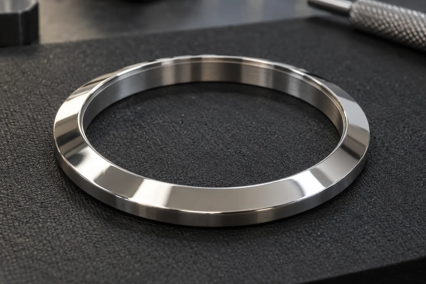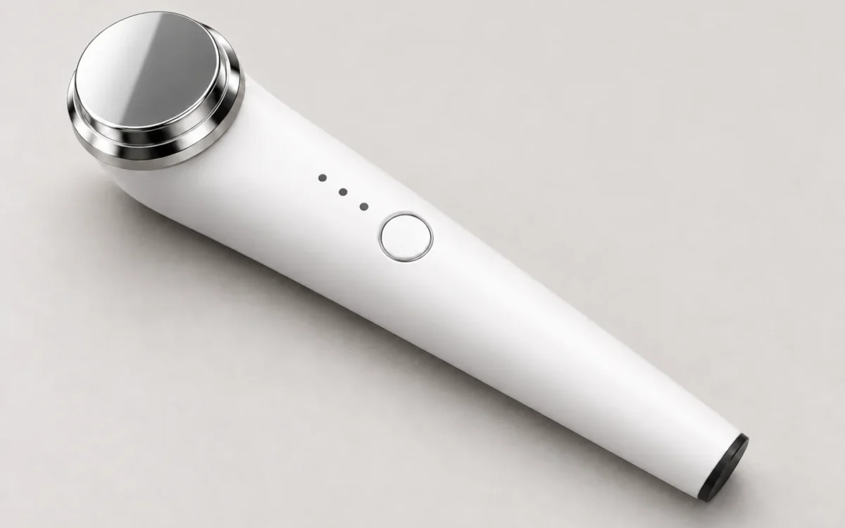
미용기기 MIM 헤드: 접촉 곡면·모서리·조립 단차의 정밀 제조
미용기기 MIM 헤드: 접촉 곡면·모서리·조립 단차의 정밀 제조
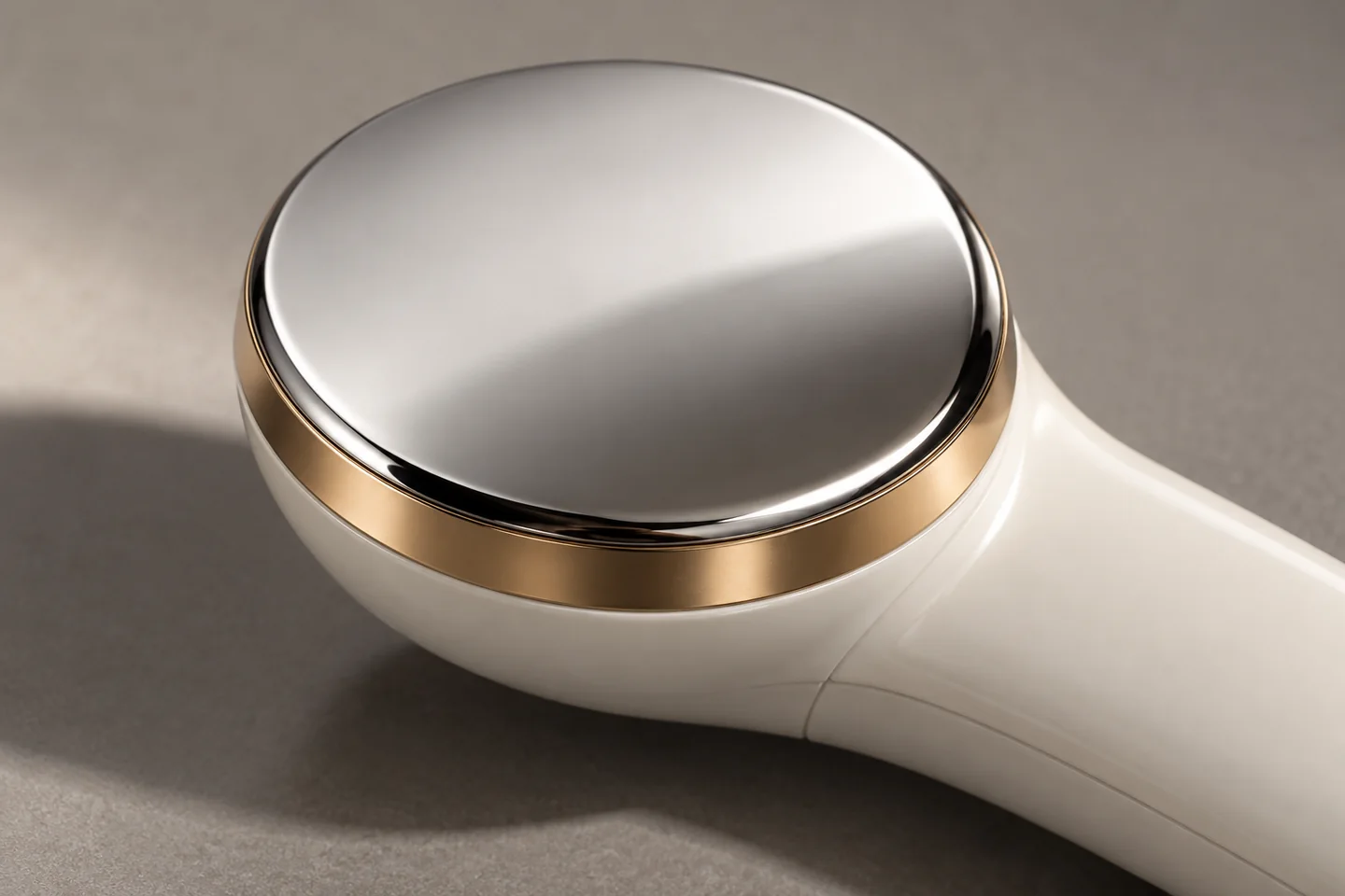
미용기기 MIM 헤드의 경면 품질은 최종 버핑만으로 결정되지 않습니다. 성형품 내부의 분말·바인더 분포는 소결 수축에, 소결 조직은 연마 후 기공 노출에, 연마 제거량은 접촉면 높이와 가장자리 형상에 영향을 줍니다. 광택 있는 접촉면을 반복 생산하려면 이 변화를 재료·금형·후가공·조립 기준으로 연결해야 합니다.
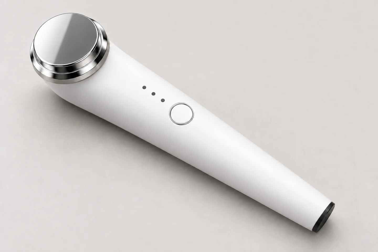
원형 디스크나 돌기가 반복되는 금속 헤드는 눈에 보이는 외관부이면서, 기기의 작동부와 사용자가 만나는 경계이기도 합니다. 넓은 면의 형상, 원주 모서리, 내부 안착면 중 어느 한 항목만 관리하면 조립 후 기울기나 국부 돌출을 놓치기 쉽습니다. 치수는 맞는데 반사선이 일그러지거나, 광택은 균일한데 가장자리 높이가 달라지는 현상이 대표적입니다.
미용기기 MIM 헤드의 제조 핵심은 성형으로 만든 복합 형상을 필요한 기능면의 후가공과 경면 마감으로 완성하는 데 있습니다. 모든 면을 정밀 절삭하는 방식도, 최종 연마에 형상 보정을 모두 맡기는 방식도 요구 품질과 원가에 맞지 않을 수 있습니다. 공정마다 확보할 형상과 다음 공정에 남길 여유를 먼저 나누어야 합니다.
1. 미용기기 MIM 헤드의 접촉면과 조립 기능을 구분합니다
금속 헤드에서는 피부와 만나는 기능 구역, 눈에 보이는 외관 구역, 내부 소자나 외장에 안착하는 조립 구역을 먼저 구분합니다. 같은 부품에 속해도 요구하는 형상과 마감, 검사의 기준이 서로 다릅니다.
헤드 중앙의 넓은 곡면과 외곽의 작은 모서리 반경은 서로 다른 형상입니다. 중앙 곡면은 부품이 피부와 만나는 전체 방향과 영역에 관여하고, 모서리는 그 면에서 측벽으로 넘어가는 국부 단면을 형성합니다. 전체를 둥글게 만든다는 표현만으로는 두 형상을 관리하기 어렵습니다.
평면형·완만한 볼록면·분할 접촉면 중 어떤 구성이 적합한지는 기기의 사용 부위, 접촉 방향, 이동 방식과 작동 구조에 따라 달라집니다. 볼록한 정도가 크거나 반경이 크다는 이유만으로 접촉 품질이 항상 좋아지는 것은 아닙니다. 넓은 면과 가장자리의 상대 위치가 실제 사용 자세에서 어떻게 작용하는지 검토해야 합니다.
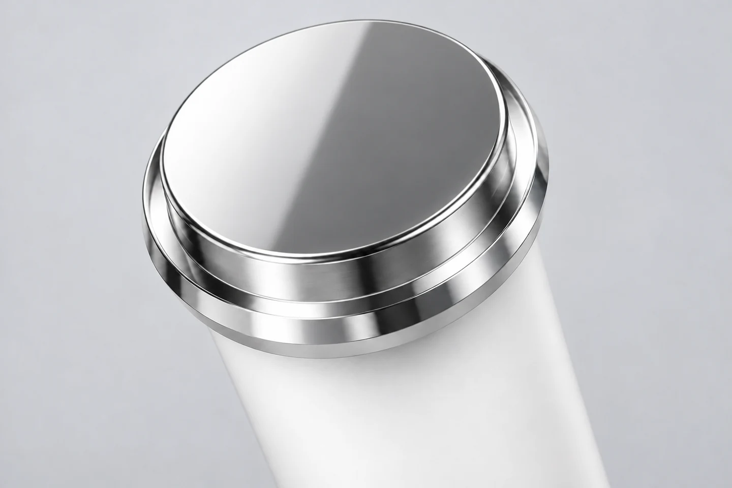
접촉 상태를 바꾸는 형상 편차
같은 외곽 크기의 부품이라도 중앙 높이와 주변부의 휨이 다르면 처음 닿는 위치가 달라질 수 있습니다. 국부적인 높이 차이는 하중 분포에도 영향을 줍니다. 실제 접촉 영역은 피부의 변형, 누르는 힘, 기울기와 사용 부위에 따라 변하므로 금속 헤드의 투영 면적을 그대로 실제 접촉 면적으로 취급하지 않습니다.
기기의 전기적·열적·기계적 작동 조건과 부품 형상은 함께 검토하되, 금속 부품의 형상 검사만으로 완성품의 출력 균일성이나 피부 적용 성능이 입증되지는 않습니다. 부품 도면에는 재현해야 할 형상을, 완성품 평가에는 실제 접촉·작동 조건을 각각 명확히 지정합니다.
연속 곡면의 연결 조건
중앙 면과 모서리 사이에 의도하지 않은 능선이나 평탄부가 생기지 않도록 단면을 확인합니다. CAD에서 접선 방향이 이어지는지, 성형 후 그 연결부에 파팅 단차가 생기는지, 연마 후 특정 구역만 평평해지는지를 순서대로 검토합니다. 외관상의 반사선은 이상 위치를 찾는 데 유용하지만 치수 판정을 대신하지는 않습니다.
원형 접촉면의 중심 높이와 원주 형상을 분리합니다
원형 디스크는 지름과 중심 높이가 같아도 원주 한쪽이 들리거나 둘레가 접시처럼 변형될 수 있습니다. 중심에서 외곽으로 향하는 방사 단면과 일정 반지름의 원주 단면을 함께 비교하면 전체 기울기, 중심부의 볼록함, 국부적인 가장자리 후퇴를 구분할 수 있습니다. 중앙 한 점의 높이와 전체 평균 편차만으로 접촉면을 판정하지 않는 이유입니다.
조립 안착면을 기준 A로 설정했다면 기능 윤곽도 그 기준에서 평가합니다. 반대로 측정 점군을 CAD에 자유롭게 최적 맞춤하면 기울기나 높이 오차의 일부가 정렬 과정에서 사라질 수 있습니다. 형상 자체를 비교하는 정렬과 조립 위치를 검증하는 정렬을 구분하고, 해당 도면의 기준 체계와 구속 조건을 검사 프로그램에 반영합니다.
2. 재질·피드스톡·소결 조직이 경면의 바탕을 결정합니다
광택을 높이려면 연마 조건뿐 아니라 그 아래에 남는 금속 조직을 함께 설계해야 합니다. 미용기기 헤드는 외측 접촉면, 얇은 측벽, 내부 체결부가 서로 다른 요구를 가질 수 있습니다. 소재 선택은 외관 색상보다 접촉 환경, 체결 하중, 최종 마감과 제조 순서에서 시작합니다.
316L과 17-4PH의 선택 기준
316L은 내식성·인성·연마성을 함께 고려하는 MIM 부품에서 검토할 수 있는 재료입니다. 17-4PH는 체결부나 얇은 목 부분처럼 높은 강도가 필요한 구조에서 후보가 되며, 석출경화 열처리 상태까지 포함해 특성을 지정해야 합니다. 같은 스테인리스라는 이유로 두 재료의 가공 순서와 성능 기준을 동일하게 적용하지 않습니다.
표면을 밝게 연마했다는 사실이 재질의 내식성이나 접촉 적합성을 대신하지는 않습니다. 반대로 높은 경도만으로 좋은 접촉 헤드를 선택할 수도 없습니다. 반복 체결 하중이 지배적인지, 넓은 경면의 외관 품질이 지배적인지, 최종 표면 상태에서 요구 환경을 만족하는지를 함께 비교합니다.

미세 분말보다 중요한 피드스톡의 균일성
분말을 미세하게 하면 소결의 구동력을 확보하는 데 유리하지만, 입도 하나로 완성품 품질이 결정되지는 않습니다. 입도 분포와 입자 형상은 충전 밀도와 바인더 요구량에 관여하며, 분말·바인더 비율은 점도와 금형 충전에 영향을 줍니다. 바인더가 부족하면 유동성이 나빠질 수 있고, 과도하면 성형 중 분리와 탈지 후 형상 유지가 문제가 될 수 있습니다.
원형의 넓은 접촉판에서 좁은 연결부로 유로가 바뀌는 구조라면, 게이트를 통과한 재료가 끝까지 균일한 조성으로 채워지는지 확인해야 합니다. 국부 분말 함량이 달라지면 소결 수축도 위치에 따라 달라질 수 있습니다. 이러한 편차를 금형 전체의 확대율만 조정해 해결하려 하면 접촉면의 휨이나 원주 방향 높이 차이가 남습니다.
새 피드스톡을 적용할 때는 공급사의 수축 계수와 유동 자료를 확인하고, 실제 금형의 충전 양상·성형품 중량·소결 후 위치별 치수를 연결해 봅니다. 전체 중량이 일정하더라도 내부 조성의 균일성이 자동으로 입증되는 것은 아닙니다. 특정 구역의 편차가 반복되면 그 위치의 단면과 국부 밀도·조직을 추가로 확인합니다.
탈지는 형상과 최종 조성을 함께 관리하는 단계입니다
탈지에서는 바인더가 빠져나가는 경로를 확보하면서 분말 골격을 유지해야 합니다. 두꺼운 보스와 얇은 접촉판이 연결된 부품은 단순 평균 두께보다 가장 두꺼운 구역의 제거 경로가 중요합니다. 탈지 과정의 균열이나 내부 손상은 후속 광택 공정으로 복구할 수 없습니다.
잔류 성분도 중요합니다. 특히 MIM 17-4PH에서는 탈지·소결 후 잔류 탄소가 상분율과 열처리 응답에 영향을 줄 수 있습니다. 탈지 감량은 공정 추적 지표로 활용하되, 감량만으로 최종 탄소량과 재료 성능을 확정하지 않습니다. 소재 성적서, 필요한 성분 분석, 소결 조직과 열처리 기록을 연결해야 합니다.
평균 밀도와 표면 기공은 별도로 판단합니다
소결 온도와 시간이 증가하면 치밀화가 진행될 수 있지만 결정립 성장도 함께 발생합니다. 따라서 온도를 높이는 것만으로 강도·치수·경면 품질이 동시에 개선된다고 볼 수 없습니다. 치밀화와 조직 변화, 지지 조건에서 생기는 변형을 함께 확인하여 공정 범위를 정합니다.
전체 밀도가 비슷한 부품도 기공의 크기·형상·분포와 표면으로 연결된 정도가 다를 수 있습니다. 표면에 열린 기공은 전해질이 닿는 면적과 국부 부식 거동에 영향을 주므로, 평균 밀도와 낮은 거칠기만으로 경면 상태를 합격시키지 않습니다. 최종 연마면의 핀홀 관찰과 필요한 단면 검사를 함께 사용합니다.
3. 금형 충전과 모서리 마감을 함께 설계합니다
버 제거는 의도하지 않은 돌출이나 날카로운 잔여 형상을 관리하는 작업입니다. 반면 목표 반경은 설계한 모서리의 기하 형상입니다. 도면에 ‘버 제거’만 적으면 일정한 반경이나 중앙 곡면과의 연결 상태까지 정해지지 않습니다.
피부에 닿거나 이동 중 접촉할 수 있는 가장자리는 적용 구간과 목표 단면을 지정합니다. 필요한 경우 반경의 허용 범위와 측정 단면을 함께 정하고, 버·파팅 단차·게이트 제거 흔적의 허용 조건은 별도 항목으로 관리합니다. 모든 미용기기에 공통으로 적용할 수 있는 안전 반경이나 표면 거칠기를 임의로 정하지 않습니다.
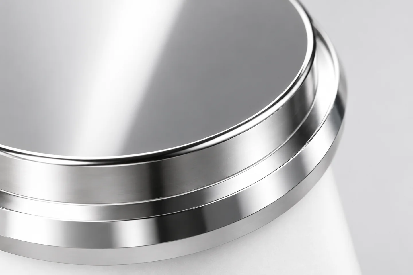
넓은 접촉판의 충전과 유동 합류부
넓은 접촉판과 좁은 연결부를 하나의 MIM 부품으로 설계한다면, 구역별 유로 단면과 충전 조건이 달라집니다. 같은 충전 유량을 유지하면서 게이트 단면을 줄이면 국부 유속과 전단 조건, 압력 손실이 달라집니다. 외관 흔적을 줄이기 위한 게이트 축소가 충전 균일성을 해치지 않는지 확인해야 합니다. 또한 보스나 구멍을 우회한 유동이 만나는 위치에는 합류 흔적이 남을 수 있습니다. 유동 해석과 단계별 충전 시편을 이용해 마지막 충전 위치, 합류부와 공기 배출 경로를 함께 확인합니다.
충전 부족을 사출 압력 하나로 보정하기보다 게이트 위치·단면, 금형 온도, 충전 속도와 피드스톡의 유동 범위를 함께 검토합니다. 성형품이 겉으로 완전히 채워졌더라도 국부적인 분말 분포와 잔류 응력이 균일하다는 뜻은 아닙니다. 성형 중 형성된 잔류응력은 탈지 과정에서 완화되며 변형으로 나타날 수 있습니다. 사출 직후의 외형뿐 아니라 탈지 후의 자세와 윤곽을 비교해야 성형 이력의 영향과 소결 중 변형을 구분할 수 있습니다. 최종 소결품의 변형 위치를 성형 단계의 유동 경로와 연결하여 원인을 좁힙니다.
게이트와 파팅라인의 배치
게이트와 금형 분할면의 흔적은 성형 후 제거·마감 경로까지 포함하여 배치합니다. 접촉면 중앙이나 곡면 전환부를 가로지르는 흔적은 후처리 과정에서 주변 형상까지 변형시킬 수 있습니다. 접촉면에서 벗어난 위치를 우선 검토하되, 유동·충전과 탈형 조건을 함께 만족해야 합니다.
흔적을 뒷면으로 옮겼더라도 조립 기준면이나 내부 소자 지지면과 겹치면 기능 문제가 남습니다. 접촉면, 기준면, 체결면을 구분한 뒤 금형 방향과 게이트 제거 공구의 접근 방향을 정합니다. 금형 흔적을 외관상 보이지 않게 하는 것과 기능면에서 제거하는 것은 구분해야 합니다.
4. 소결 수축의 크기와 변형 방향을 분리하여 제어합니다
헤드의 뒷면에는 설계에 따라 체결 보스, 소자 안착부, 위치 결정부가 배치될 수 있습니다. 이 형상들이 두꺼운 구역을 만들면 주변의 얇은 접촉면과 충전·탈지·소결 거동이 달라질 수 있습니다. 외형 곡률을 안정적으로 만들려면 보이지 않는 내부 단면부터 검토해야 합니다.
두께 전이와 국부 재료 집중
가능한 범위에서 두께를 균일하게 유지하고 두께가 바뀌는 구역은 급격한 전이를 줄입니다. 보스에는 체결에 필요한 길이와 잔여 벽을 확보하면서 코어 형상으로 불필요한 재료 집중을 줄이는 방안을 검토합니다. 보스 뿌리의 필렛도 필요하지만 과도한 보강으로 두꺼운 덩어리를 만드는 것은 피해야 합니다.
외관면을 지지하기 위해 리브를 추가할 때도 같은 문제가 있습니다. 리브가 많다는 사실만으로 형상 안정성이 확보되지는 않습니다. 리브 교차부의 두께, 충전 방향, 소결 중의 지지 상태와 후가공 고정 위치가 서로 맞아야 합니다.
수축 보정과 소결 지지의 구분
s = (Lg − Lf) / Lg
Lg = Lf / (1 − s)
Lg는 성형품 기준 길이, Lf는 소결 후 길이, s는 해당 방향의 선형 수축률입니다. 가상으로 s = 15%라면 성형품 길이는 목표 소결 길이의 약 1.176배가 됩니다. 수축률 15%와 확대율 15%는 같은 계산이 아닙니다. 이 값은 실제 헤드의 수축률이 아니라 관계를 설명하기 위한 예시입니다.
실제 금형 캐비티를 정할 때는 이 소결 관계에 성형 단계의 치수 변화, 캐비티별 편차와 후가공 여유까지 연결합니다. 공급사 수축 계수는 출발 자료이며, 실제 형상과 공정으로 만든 시편의 방향별·위치별 수축을 확인해야 합니다. 계수가 금형 캐비티부터 소결품까지의 총수축을 포함하는지 기준 단계를 확인하고, 이미 포함된 성형 수축은 다시 반영하지 않습니다.
금형을 전체적으로 확대하는 수축 보정은 목표 크기를 맞추는 출발점입니다. 휨·기울기·비대칭 변형처럼 위치에 따라 달라지는 편차까지 하나의 확대율로 해결할 수는 없습니다. 반복 시편에서 변형의 위치와 방향을 확인하고 형상, 공정 조건과 소결 지지를 함께 조정합니다.
소결 받침은 부품을 지지하는 위치와 접촉 조건에 따라 형상에 영향을 줄 수 있습니다. 접촉 흔적이 최종 외관면에 남는지, 수축을 방해하는 구속이 생기는지, 지지되지 않은 긴 구간이 있는지 확인합니다. 관련 공정의 기본 관계는 MIM 소결 수축과 금형 보정 설계와 연결됩니다.
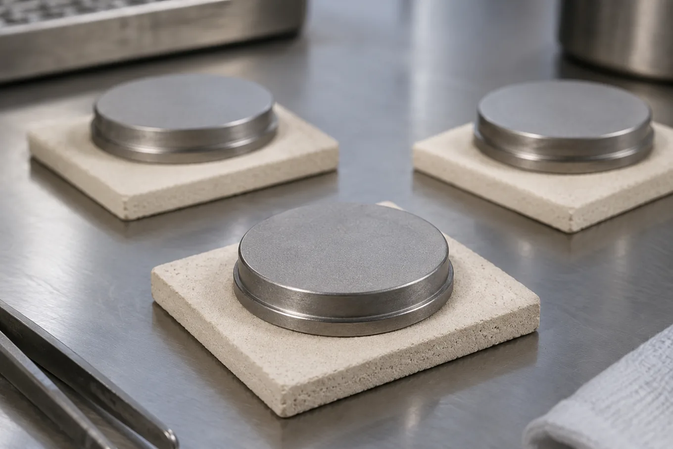
원주 처짐과 지지 흔적의 상충
원판을 중앙에서만 받치면 바깥쪽의 지지되지 않은 구간이 문제될 수 있고, 반대로 둘레와 받침 사이의 마찰이 수축 방향의 이동을 제한하면 자유 수축이 방해될 수 있습니다. 소결 받침은 넓게 받치는 것만으로 정해지지 않습니다. 접촉 위치, 받침과 소재의 상대 이동, 마찰과 수축 방향을 함께 검토해야 합니다.
같은 캐비티에서 나온 부품도 적재 방향과 받침 위치에 따라 변형 양상이 달라진다면 금형 치수 보정보다 지지 조건을 먼저 분리해 확인합니다. 변형이 캐비티를 따라 반복되는지, 소결 배치를 따라 반복되는지 구분하면 금형·성형·열공정 중 편차를 발생시키는 주요 공정을 좁힐 수 있습니다.
5. 선택 후가공은 조립 기준과 접촉판 강성을 함께 다룹니다
MIM으로 전체 외형과 내부 형상을 만든 뒤 필요한 기능면을 선택적으로 절삭·연삭할 수 있습니다. 대표적인 대상은 부품의 높이를 결정하는 안착면, 체결 보스의 끝면, 상대 부품과 위치를 맞추는 구멍입니다. 모든 면에 동일한 가공 공차를 적용하기보다 조립 결과에 직접 영향을 주는 구역을 먼저 정합니다.
측정 기준과 가공 기준의 일치
외곽을 기준으로 고정하여 보스 높이를 가공했는데 최종 조립은 다른 안착면을 기준으로 이루어진다면, 가공된 높이와 실제 접촉면 높이 사이에 추가 편차가 생길 수 있습니다. 가공 기준, 검사 기준, 조립 기준의 관계를 도면에서 연결해야 합니다.

얇은 접촉판의 강성과 클램핑 해제 후 형상
평탄하고 균일한 등방성 얇은 판을 작은 처짐 조건의 선형 탄성 범위에서 다루면 굽힘 강성은 D = Et³ / [12(1 − ν²)]로 표현됩니다. E는 탄성계수, t는 두께, ν는 푸아송비입니다. 같은 재료에서 두께가 감소하면 강성이 세제곱 비율로 감소하므로, 외관 연마 여유와 최종 잔여 두께는 고정 하중에 대한 변형까지 연결해 검토해야 합니다.
실제 헤드에는 곡률·보스·리브·단차가 있으므로 이 식으로 완제품 변형량을 확정할 수 없습니다. 지지 위치와 클램핑 하중을 포함한 해석·시편 비교가 필요합니다. 특히 지그가 변형된 소재를 강제로 평평하게 누른 상태에서 가공하면 해제 후 형상이 달라질 수 있습니다. 가공 중 기준 재현성, 해제 후 자유 상태, 최종 체결 상태를 구분하여 확인합니다.
안착 기준의 재현성과 기능면 가공 순서
원형 외경이 잘 만들어져 있어도 실제 조립에서 높이를 결정하는 면이 따로 있다면 외경만으로 위치를 잡아서는 부족합니다. 안착면으로 높이와 기울기를 정하고, 위치 결정 형상으로 중심을 정하며, 필요한 경우 회전 방향을 정하는 구속을 추가합니다. 부품마다 다른 돌출부를 지그가 임의로 누르지 않도록 접촉 위치를 도면 기준과 일치시킵니다.
보스 끝면·위치 결정 구멍·접촉면의 상대 위치가 중요하면 가능한 범위에서 같은 기준 설정을 공유하는 가공 순서를 검토합니다. 공정이 나뉠수록 재고정 편차가 추가되므로, 가공 공차만 작게 정하는 것보다 기준을 옮기는 횟수와 그 반복성을 먼저 관리하는 편이 효과적입니다.
후공정에 남겨야 할 가공 여유
가공 완료 치수와 출하 치수는 항상 같지 않습니다. 연마에서 재료가 제거되고 표면처리로 치수가 달라질 수 있기 때문입니다. 마감이 적용되는 구역과 보존해야 할 기준면을 지정하고, 외관 형상에 필요한 여유와 조립 치수에 필요한 여유를 구분합니다.
기능면의 선택 가공과 지그 구성은 CNC 정밀가공의 기준면 설정과 함께 계획할 수 있습니다. 소결품의 편차를 후가공으로 어디까지 보정할지 먼저 정하면 불필요한 전면 가공과 연마량을 줄이는 방향으로 공정을 구성할 수 있습니다.
6. 미용기기 MIM 헤드의 경면 연마 공정을 단계별로 구성합니다
경면 품질을 결정하는 형상·파상도·거칠기의 분리
원형 접촉판을 경면으로 마감할 때는 반사되는 밝기와 면의 정확도를 구분해야 합니다. 미세한 연마 자국을 줄여 광택을 높여도 접촉판 전체가 접시처럼 휘어 있거나 중간 간격의 굴곡이 남을 수 있습니다. 앞의 편차는 설계 윤곽과의 차이로, 표면 텍스처는 정해진 파장 대역의 파상도와 거칠기로 나누어 확인합니다. 따라서 같은 Ra를 만족하는 두 부품도 반사선의 연속성과 원주 주변의 접촉 형상은 달라질 수 있습니다.
경면 요구는 ‘유광’이라는 단어만으로 발주하기 어렵습니다. 비교 견본의 조명·관찰 방향을 맞추고, 미세 흠집·흐린 영역·점상 결함의 허용 조건을 정해야 합니다. 이 외관 판정과 별도로 접촉판 윤곽, 모서리 단면, 최종 높이를 관리하면 광택을 맞추는 과정에서 기능 형상이 손실되는 문제를 구분할 수 있습니다.
형상 보정과 최종 광택 공정의 역할
초기 가공 흔적이 깊은 상태에서 부드러운 버프만 오래 대면 높은 부분은 먼저 깎이고 깊은 홈은 남기 쉽습니다. 연삭이나 형상을 지지할 수 있는 연마 단계에서 앞 공정의 흔적을 정리한 뒤 더 미세한 연마 단계로 넘어가야 합니다. 각 단계 사이에 잔류 연마재를 제거하지 않으면 이전 단계의 큰 입자가 미세 연마면에 새로운 흠집을 만들 수 있습니다.
기계 연마는 연마재와 공구의 접촉으로 재료를 제거합니다. 버핑은 유연한 휠·천 등의 접촉 특성을 이용하는 마감 방식이므로 원주 끝까지 감싸 들어가는 접촉에 주의해야 합니다. 가장자리가 말리듯 낮아지는 롤오프는 중앙 조도만 측정해서는 놓치기 쉽습니다. 원형 접촉판에서는 중심에서 원주로 이어지는 단면을, 리브형 헤드에서는 정상부와 골을 따로 확인해야 하는 이유입니다.
Δz(x,y) ≈ K ∫ p(x,y,t) v(x,y,t) dt
기계 연마의 국부 제거 깊이 Δz를 설명하는 Preston형 근사 관계입니다. p는 해당 위치의 접촉 압력, v는 공구와 표면의 상대속도이며, 적분은 접촉 시간에 따른 누적을 뜻합니다. K는 재료·연마재·공구·액체 및 운전 조건에 의존하는 실험 계수입니다.
장비에 설정한 힘과 회전수가 같아도 국부 제거량은 같지 않습니다. 곡률과 공구의 변형이 접촉 면적·압력 분포를 바꾸고, 공구 경로의 중첩과 가장자리 통과가 위치별 접촉 시간을 바꾸기 때문입니다. 이 관계식은 조건 차이를 이해하는 근사 모델이며, 실제 헤드에서 제거량을 예측하려면 시험 가공으로 계수와 적용 범위를 확인해야 합니다. 전해연마의 제거량 계산에 그대로 적용하지 않습니다.
전해연마와 패시베이션을 구분하는 이유
전해연마는 부품을 양극으로 두고 전기화학적으로 표면을 용해하는 제거 공정입니다. 기계 공구가 직접 닿지 않는 면에도 적용을 검토할 수 있지만, 전류 분포·전극 배치·초기 표면 상태가 결과에 관여합니다. 미세 요철이 개선되는 동안 전체 높이와 모서리도 달라질 수 있으므로, 기계 연마를 무조건 대체하는 최종 단계로 지정하기보다 제거 여유와 요구 형상을 함께 검토합니다.
스테인리스의 화학적 패시베이션은 표면의 외래 철 오염 제거와 적절한 부동태 상태를 위한 처리입니다. 깊은 가공 흠집이나 휨을 평탄화하는 경면 공정과는 역할이 다릅니다. 마감 후 눈에 보이는 광택이 확보되어도 잔류 연마재·유분·외래 금속 오염이 없다는 뜻은 아니므로 세정과 필요한 표면처리, 처리 결과의 확인을 별도로 계획합니다.
기공 노출과 과도 연마를 서로 다른 원인으로 판별
MIM 소결체에 잔류한 표면 근처의 기공은 재료가 제거되면서 드러날 수 있습니다. 반면 연마 중 개재물 탈락이나 국부적인 과도 제거도 점상 결함을 만들 수 있습니다. 점이 보인다는 이유만으로 소결 기공이라고 단정하지 않고, 확대 관찰과 필요 시 단면 분석으로 기공·탈락·잔류물을 구분해야 합니다. 전체 밀도 한 값도 특정 접촉면의 기공 분포를 직접 설명하지 못합니다.
연마를 계속할수록 표면이 불규칙하게 거칠어지는 오렌지필 양상이 나타난다면 압력과 시간을 더 늘리는 방식은 적절하지 않습니다. 재료 조직·경도와 공구의 유연성, 단계별 제거 조건을 검토해야 합니다. 이러한 과도 연마 문제와 원래 존재한 기공의 노출을 분리해야 재연마 가능한 불량과 소재·소결 단계로 되돌아가야 할 불량을 판단할 수 있습니다.
원형 평면과 반복 리브에 서로 다른 경로를 적용합니다
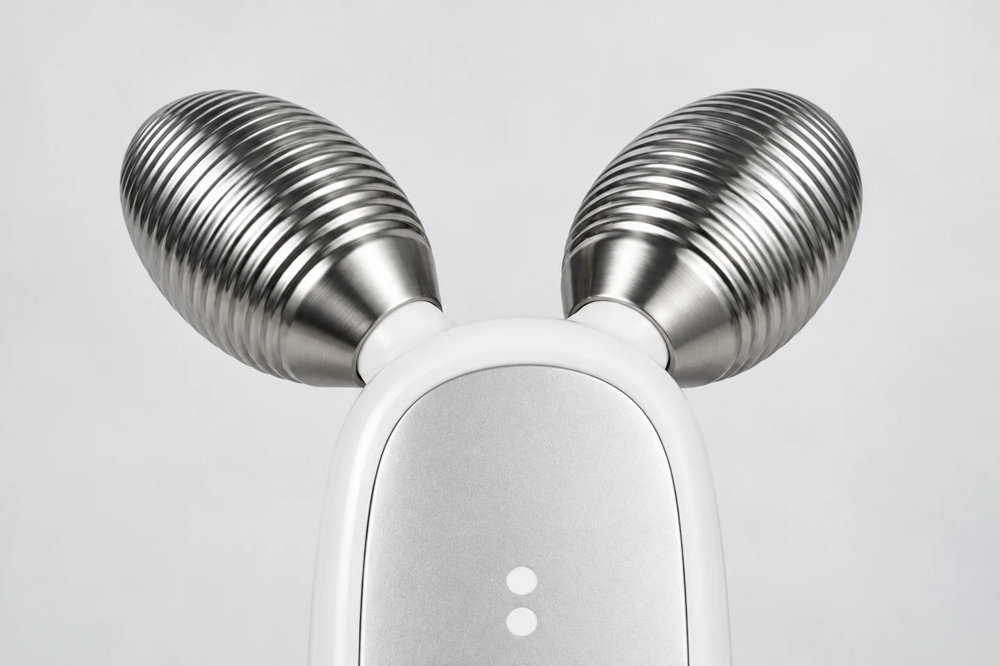
원형 디스크 헤드는 넓은 접촉면과 원주 모서리의 연결을 함께 관리합니다. 반면 반복 리브가 있는 곡면 헤드는 정상부와 골 부분에 공구가 닿는 조건이 다릅니다. 정상부에 공구가 오래 머물면 리브 높이가 먼저 줄어들고, 골에는 앞 공정의 흔적이 남을 수 있습니다. 같은 광택을 목표로 하더라도 공구 크기·강성·접근 방향과 경로를 형상에 맞춰 나누어야 합니다.
외관 구역과 조립 기준면에 동일한 연마를 적용할 필요는 없습니다. 접촉면과 모서리의 요구 마감을 확보하면서 안착면·나사부·위치 결정부가 불필요하게 제거되지 않도록 노출 범위와 지그 구성을 정합니다. 최종 연마의 목적은 초기 형상 불량을 가리는 것이 아니라 앞 단계에서 확보한 형상 위에 요구 표면을 만드는 것입니다.
기공과 경면의 관계는 MIM 경면 품질과 표면 기공·연마 공정과 연결됩니다. 표면처리 방식의 명칭만 정하기보다 처리 전후 윤곽과 제거량을 비교해야 공정 선택의 타당성을 확인할 수 있습니다.
7. 연마 제거량을 포함해 최종 조립 단차를 계산합니다
금속 헤드와 상대 외장의 경계에서는 외관 틈의 폭과 표면 높이 차이가 서로 다른 항목입니다. 접촉면이 외장과 같은 높이로 이어지는지, 일정하게 돌출되는지, 일부만 기울어지는지는 조립된 상태의 상대 높이로 판단합니다. 실제 기능에 따라 의도한 높이 관계를 먼저 정해야 합니다.

Δh = hm − hp
공통 조립 기준 A에서 해당 위치의 금속 접촉면까지 높이를 hm, 상대 외장면까지 높이를 hp로 정의하면 국부 높이 차이는 Δh입니다. 같은 방향에서 비교하며, 양수는 금속면이 상대 외장면보다 높은 경우를 뜻합니다.
Δhmin = hm,min − hp,max
Δhmax = hm,max − hp,min
두 유효 높이의 한계값을 조합한 단순 공차 검토입니다. 부품이 실제로 안착한 위치, 변형, 기울기와 각 기능면의 최종 마감을 포함하여 유효 높이를 정의해야 합니다.
연마 제거량을 포함하는 조립 높이 계산
연마 전 치수에서 출발하는 단순 축방향 모델은 Δh = H₀ − a + b − P로 쓸 수 있습니다. H₀는 금속 안착면에서 접촉면까지의 연마 전 높이, a는 접촉면의 축방향 제거량, b는 공통 기준에서 금속 안착면까지의 조립 높이, P는 같은 기준에서 상대 외장면까지의 높이입니다. 안착면은 연마에서 보존되고, 기울기·체결 변형·표면층 추가가 없는 조건입니다.
공차 연쇄를 설명하기 위한 가상 계산입니다. 실제 제품 치수나 공정 보장값이 아닙니다.
H₀ = 2.100 ± 0.025 mm, a = 0.020 ± 0.005 mm, b = 0.030 ± 0.010 mm, P = 2.000 ± 0.020 mm로 가정합니다.
Δh₀ = 2.100 − 0.020 + 0.030 − 2.000 = 0.110 mm
T = 0.025 + 0.005 + 0.010 + 0.020 = 0.060 mm
0.050 mm ≤ Δh ≤ 0.170 mm
한계 조합의 결과입니다. 모델에 포함하지 않은 국부 기울기·체결 변형·불완전 안착과 측정 불확도는 별도로 평가합니다. 이미 b에 반영한 안착 높이 변동은 다시 가산하지 않습니다. 분포와 상관관계가 확인되지 않은 공차를 통계적으로 줄여 계산하지 않습니다.
이미 연마 후 완성 높이 Hf를 측정했다면 Δh = Hf + b − P로 계산합니다. 이때 Hf에 포함된 제거량 a를 다시 빼거나 그 변동을 중복 가산하면 같은 공정 영향을 두 번 계산하게 됩니다. 부품 도면의 완성 치수와 공정 중간 치수를 구분하는 것이 계산식보다 먼저입니다.
대표 높이 한 점으로 끝내지 않는 이유
중앙 높이가 맞아도 원주 방향의 주변부나 모서리에서 상대 높이가 달라질 수 있습니다. 원형 헤드는 중심을 지나는 여러 단면과 원주상의 비교 위치를 정하고, 길쭉한 헤드는 길이·폭 방향의 단면과 모서리 전환부에서 높이 관계를 확인합니다. 부품의 기울기와 휨은 단순 평균값으로 없어지지 않습니다.
나사 체결이나 스냅 결합 후에는 안착 상태와 부품 변형이 바뀔 수 있습니다. 보스 끝면만 합격시킨 뒤 완성 조립 상태를 확인하지 않으면 체결 위치별 편차를 놓칠 수 있습니다. 최종 체결 조건을 재현한 검사와 부품 단품 검사를 구분합니다.
통계적 공차 계산의 적용 조건
독립적인 변동과 분포가 확인되지 않은 상태에서 제곱합 제곱근 방식으로 공차를 합성하면 위험한 조합을 과소평가할 수 있습니다. 공정 자료가 부족한 단계에서는 한계 조합을 확인하고, 양산 데이터로 분포·상관관계·공정 중심 이동을 검토한 뒤 통계 모델의 적용 여부를 정합니다.
8. 경면의 윤곽·텍스처·국부 결함을 다른 측정으로 검증합니다

곡면 윤곽은 목표 형상과의 차이를 다룹니다. 표면 텍스처는 측정과 필터 조건에 따라 더 긴 간격의 파상 성분과 미세한 거칠기 성분으로 구분하여 분석할 수 있습니다. Ra가 낮게 측정되었다는 사실만으로 헤드 전체의 곡률이나 모서리 반경이 맞는 것은 아닙니다.
곡면을 제거한 조도값과 남겨야 할 형상 정보
곡면 위에서 거칠기를 평가할 때는 기준 형상을 제거하는 처리와 필터 조건이 결과에 영향을 줍니다. 그런데 접촉면의 휨을 검사하는 목적이라면 그 휨을 단순한 기준 형상으로 제거해서는 안 됩니다. 무엇을 측정하는지에 따라 정렬과 형상 제거 방법을 다르게 정해야 합니다.
윤곽·형상 검사는 도면의 기준 체계에 맞춰 정렬합니다. 모든 데이터를 자유롭게 움직여 편차를 최소화하는 최적 맞춤 결과만 사용하면, 실제 조립에서 중요한 위치 오차가 작게 보일 수 있습니다. 도면 기준 정렬과 형상 자체를 비교하기 위한 최적 맞춤을 목적에 따라 구분합니다.
| 검토 대상 | 확인할 정보 | 측정에서 고정할 조건 |
|---|---|---|
| 접촉 곡면 | 설계 윤곽에 대한 높이·기울기·국부 형상 편차를 확인합니다. | 기준 정렬, 비교 단면과 측정 위치를 지정합니다. |
| 외곽 모서리 | 반경과 곡면 연결, 국부 버·단차를 확인합니다. | 관찰 방향과 단면, 확대 배율 및 평가 구간을 정합니다. |
| 표면 텍스처 | 거칠기와 필요한 파상 성분을 구분합니다. | 표준·판, 필터, 평가 길이, 형상 제거와 측정 방향을 기록합니다. |
| 완성 조립 | 상대 외장과의 높이 차이·기울기를 확인합니다. | 공통 기준, 체결 조건, 검사 위치를 재현합니다. |

경면의 광학 측정에서 확인해야 할 데이터 범위
경면은 광학 측정 자체가 불가능한 표면이 아닙니다. 간섭계는 적절한 조건에서 매끄러운 고반사면을 측정할 수 있습니다. 다만 원주 전환부의 기울기가 커지면 반사광이 대물렌즈의 수광 범위를 벗어나고 측정점이 누락될 수 있습니다. 높은 개구수 렌즈가 경사 수용 범위를 넓히더라도 시야와 작업거리에는 제약이 생길 수 있습니다.
따라서 중앙의 매끄러운 영역에서 얻은 데이터만으로 모서리까지 합격시켜서는 안 됩니다. 유효 측정 영역과 결측 위치를 먼저 확인하고, 필요하면 부품 자세 변경이나 다른 측정 원리를 병용합니다. 결측을 보간해 채운 면과 실제 취득한 면을 구별해야 광택 있는 외관과 정량적인 형상 검증이 함께 성립합니다.
Ra와 국부 결함의 구분
Ra는 평가 구간에서 거칠기 프로파일 높이 편차의 절댓값을 평균한 값입니다. 깊고 좁은 흠집 하나와 넓게 분포한 미세 요철은 다른 표면인데도 평균값이 비슷할 수 있습니다. 따라서 경면의 흠집·핀홀·가장자리 손상은 위치와 크기를 별도로 기록하고, 기능에 필요한 다른 프로파일 또는 면적 매개변수를 선택합니다.
표면의 가공 결을 가로지르는 방향과 그에 평행한 방향은 서로 다른 결과를 줄 수 있습니다. 같은 부품의 개선 전후를 비교할 때는 측정 위치·방향·형상 제거·필터·평가 길이와 장비 조건을 맞춰야 합니다. 단면 측정과 면적 측정은 서로 보완할 수 있지만 Ra와 Sa를 같은 값으로 취급하지 않습니다.
모서리의 설계 반경은 조도계 한 번의 스캔으로 자동 판정되는 항목이 아닙니다. 접근 가능한 단면과 탐침 끝 형상, 광학계의 경사 수용 범위를 고려하고, 윤곽 검사와 국부 확대 관찰을 조합하여 버·롤오프·반경 편차를 구분합니다.
측정 반복성과 공정능력을 구분합니다
같은 위치에서 장비만 반복 작동하는 시험은 부품 재고정과 기준 재설정의 영향을 충분히 포함하지 않습니다. 실제 검사와 같이 탈착·재안착한 반복 측정에 작업자와 측정일 조건을 더하여 장비 변동, 기준 재현성, 장기 변화를 구분합니다. 허용 편차와 비슷한 크기의 측정 변동이 존재하면 부품 간 차이와 검사 과정의 차이를 분리하기 어렵습니다.
양산 데이터는 캐비티·소결 배치·지그·연마 조건별로 먼저 살펴봅니다. 서로 다른 중심을 가진 집단을 혼합하면 전체 분포가 여러 봉우리를 가질 수 있습니다. 공정이 안정되고 분포 가정이 타당한 조건에서 Cpk = min[(USL − μ)/(3σ), (μ − LSL)/(3σ)]를 해석합니다. USL·LSL은 규격 한계, μ·σ는 해당 공정의 평균과 표준편차입니다. 표본 추정치에는 불확실성이 있으므로 초도 소수품의 합격이나 높은 지수 하나를 장기 품질 보장으로 바꾸지 않습니다.
9. 불량의 발생 단계를 추적해 양산 공정을 보정합니다
미용기기 MIM 헤드의 최종 불량은 겉으로 비슷해도 출발 공정이 다를 수 있습니다. 경면에 점이 보인다고 모두 소결 불량은 아니며, 원주 높이가 달라졌다고 모두 금형 치수 문제도 아닙니다. 소결 직후, 기능면 가공 후, 중간 연마 후, 최종 마감 후와 조립 후의 측정값을 연결해야 재작업 방향을 정할 수 있습니다.
| 최종 관찰 현상 | 구분해야 할 원인 | 추가 확인과 보정 방향 |
|---|---|---|
| 광택은 높지만 원주 반사선이 굽습니다. | 초기 소결 휨, 중간 파장 굴곡과 국부 과도 연마를 구분합니다. | 소결·가공·연마 후의 동일 단면을 비교합니다. 실제 형상이 맞는지 확인한 뒤 조도 조건을 조정합니다. |
| 연마할수록 점상 결함이 늘어납니다. | 기공 노출, 개재물 탈락, 연마재 잔류와 신규 흠집을 구분합니다. | 결함 깊이·분포를 확대 관찰하고 필요한 단면을 확인합니다. 소재 결함을 최종 버핑으로 계속 제거하지 않습니다. |
| 중앙 치수는 맞지만 가장자리가 낮습니다. | 소결 단계의 접시형 변형과 연마 단계의 롤오프를 구분합니다. | 방사·원주 단면을 비교하고 공구의 가장자리 통과, 지지 조건과 국부 제거량을 조정합니다. |
| 단품은 합격하지만 조립 후 한쪽이 돌출됩니다. | 안착면 위치, 상대 외장 치수, 체결 순서와 탄성 변형을 확인합니다. | 공통 기준의 공차 연쇄와 최종 체결 상태를 재현합니다. 평균 높이만으로 판정하지 않습니다. |
| 일부 캐비티나 소결 배치에서만 편차가 큽니다. | 금형·성형 요인과 적재·받침·열공정 요인을 구분합니다. | 집단을 섞기 전에 캐비티·배치별 분포를 비교하고 위치별 윤곽 편차의 반복성을 확인합니다. |
초도품에서 고정할 공정 기준
초도 검토에서는 외관이 가장 좋은 한 개를 기준으로 삼기보다, 반복 생산한 부품에서 기준을 재현할 수 있는지 확인합니다. 금형 캐비티, 피드스톡 배치, 소결 적재 조건, 후가공 지그와 연마 경로를 추적하면 변동이 커지는 구역과 단계를 연결할 수 있습니다.
접촉면 윤곽과 안착 높이는 공정 중간값을 남겨 변화량을 확인하고, 최종 외관은 합의한 조명·관찰 방향·결함 기준으로 비교합니다. 측정 지표가 서로 다르면 합격 판정도 따로 관리합니다. 높은 광택이 낮은 형상 편차를 의미하지 않으며, 낮은 Ra가 국부 핀홀의 부재를 의미하지도 않습니다.
도면·마감·수량을 연결한 제작 검토
제작 검토에는 외형 3D와 기준이 지정된 2D 도면, 접촉 구역, 최종 마감, 내부 체결 형상, 상대 외장과의 높이 관계가 필요합니다. 재질과 열처리 상태, 선택 후가공 구역, 보존할 안착면, 외관 비교 조건과 생산 수량을 함께 정하면 금형으로 확보할 부분과 후공정에서 완성할 부분을 구분할 수 있습니다.
공차를 좁히는 대상도 기능에 따라 선택합니다. 조립 높이를 결정하는 면은 후가공과 측정 기준을 연결하고, 넓은 경면은 소결 바탕과 단계별 제거량을 연결합니다. 요구가 낮은 숨은 면까지 동일한 경면·공차로 지정하면 실제 기능 개선 없이 가공 시간과 검사 부담이 늘어날 수 있습니다.
미용기기 MIM 헤드의 완성도는 재질과 소결 조직을 바탕으로, 형상을 보존하는 연마와 최종 조립 기준을 연결할 때 확보됩니다. 접촉면의 광택·윤곽·모서리·높이를 각각 정의하고 공정 간 변화량을 관리하는 것이 반복 생산 품질의 핵심입니다.
English edition
MIM beauty-device heads: precision manufacturing of contact contours, edges and assembly height
A MIM beauty-device head’s mirror finish depends on more than final buffing. Powder and binder distribution within the green part affects sintering shrinkage; sintered microstructure affects pore exposure after polishing; and polishing removal affects contact-surface height and edges. Repeatable glossy surfaces require these changes to be connected through material selection, mold design, secondary machining and assembly datums.
A circular disc or head with repeated projections is both a visible component and the interface between the device’s operating elements and user. Controlling only the broad face, circumferential edge or internal seat can miss assembled tilt or local protrusion. Dimensions may pass while reflected lines distort; gloss may be uniform while edge heights vary.
MIM beauty-device heads combine molded complex geometry with selective machining of functional surfaces and controlled mirror finishing. Machining every surface, or leaving all shape correction to final polishing, may not meet quality and cost requirements. Define the geometry each process must establish and the allowance it must leave for the next stage.
1. Separate contact-surface and assembly functions
Distinguish the skin-contact region, visible exterior and assembly region seating against an internal component or housing. These regions belong to one metal head but require different geometry, finishes and inspection references.
The broad central contour and small perimeter radius are distinct features. The central contour influences contact direction and area; the edge defines the local transition into the sidewall. An instruction to make the whole head rounded does not adequately define both.
Choosing flat, gently convex or segmented contact surfaces depends on the application area, contact direction, movement and operating mechanism. Greater convexity or a larger radius does not always improve contact. Assess the broad face and perimeter’s relative positions in the intended operating orientation.
Geometry deviations that change contact
Components with the same overall outline can first touch at different locations if their central height or peripheral bow differs. Local height differences also affect load distribution. Actual contact area varies with skin deformation, applied force, inclination and application area; the projected area of the metal head must not be treated as its actual contact area.
Review electrical, thermal and mechanical operating conditions alongside geometry. Component-shape inspection alone does not demonstrate complete-device output uniformity or performance on skin. Define the required geometry on the component drawing and actual contact and operating conditions in complete-device evaluation.
Continuity between surfaces
Check sections for unintended ridges or flat regions between the central face and edge. Examine CAD tangent continuity, parting-line steps after molding and local flattening after polishing. Reflected lines help locate irregularities but do not replace dimensional assessment.
Central height versus circumferential form
Discs with identical diameter and central height may have a raised edge or dish-shaped perimeter. Compare radial sections with circumferential sections at fixed radii to distinguish tilt, central convexity and local edge recession. One central height and an average deviation cannot establish the entire contact surface.
If the assembly seat is datum A, assess the functional profile from that datum. Freely best-fitting the measured point cloud to CAD can absorb tilt or height error. Distinguish shape-only alignment from assembly-position verification, and implement the drawing’s datums and constraints in the inspection program.
2. Material, feedstock and sintered microstructure establish the mirror-finish foundation
Higher gloss requires control of polishing and the underlying metal microstructure. Contact face, thin sidewall and internal fasteners can have different requirements. Select material from the contact environment, fastening loads, final finish and process sequence rather than appearance alone.
Choosing between 316L and 17-4PH
316L is a MIM candidate where corrosion resistance, toughness and polishability matter together. 17-4PH is a candidate for higher-strength structures such as fasteners or a thin neck; specify its properties with the precipitation-hardening condition. Being stainless steels does not justify identical processing or acceptance criteria.
A bright finish does not establish corrosion resistance or contact suitability. High hardness alone likewise does not establish suitability. Compare whether repeated fastening loads or broad mirror-surface appearance governs the design, and whether the finished surface meets the intended environmental requirements.
Feedstock uniformity beyond powder fineness
Finer powder can increase the sintering driving force, but size alone does not determine quality. Particle-size distribution and shape influence packing and binder demand; powder-to-binder ratio affects viscosity and filling. Insufficient binder can impair flow; excess binder can promote separation during molding and impair shape retention after debinding.
Where flow changes from a broad contact plate to a narrow connection, confirm uniform composition throughout the filled cavity. Local powder-content differences can create nonuniform sintering shrinkage. Correcting only the overall mold scale can leave contact-surface bow or circumferential height differences.
When introducing a new feedstock, review the supplier’s shrinkage factor and flow data, then connect actual mold-filling behavior, green-part mass and post-sintering dimensions at defined locations. Constant total mass does not automatically demonstrate uniform internal composition. If a deviation recurs in a particular region, examine its cross-section and, where needed, local density and microstructure.
Debinding controls shape and final composition
Debinding must allow binder removal while preserving the powder skeleton. With thick bosses joined to a thin plate, the removal path through the thickest region matters more than average thickness. Subsequent polishing cannot repair debinding cracks or internal damage.
Residual constituents also matter. In MIM 17-4PH in particular, residual carbon after debinding and sintering can affect phase fractions and the response to heat treatment. Debinding mass loss can be used as a process-tracking indicator, but it does not by itself establish final carbon content or material performance. Connect material certificates, any necessary composition analysis, sintered microstructure and heat-treatment records.
Average density versus surface pores
Increasing sintering temperature and time can promote both densification and grain growth. Higher temperature therefore does not ensure simultaneous improvements in strength, dimensions and mirror finish. Define the process window from densification, microstructural change and support-related distortion together.
Similar bulk densities can conceal different pore sizes, shapes, distributions and surface connectivity. Open pores affect electrolyte exposure and local corrosion, so average density and low roughness alone cannot qualify a mirror surface. Inspect final-surface pinholes and examine sections where needed.
3. Design mold filling and edge finishing together
Deburring controls unintended projections and sharp remnants; a target radius defines designed geometry. A “remove burrs” note alone does not specify a consistent radius or its transition into the central contour.
Identify edges touching skin or potentially contacting it during movement, and define their sections. Specify radius ranges and inspection sections where needed. Treat burrs, parting-line steps and gate-removal marks separately. Do not assign a universal safe radius or roughness to all beauty devices.
Broad-plate filling and flow-front junctions
If a broad contact plate and narrow connection form one MIM part, their flow sections and filling conditions differ. Reducing gate area at constant volumetric flow changes local velocity, shear and pressure loss. Confirm that a smaller visible gate mark does not compromise filling uniformity. Flow fronts passing around bosses or holes may leave weld marks. Use flow analysis and staged short shots to inspect last-to-fill regions, junctions and air-escape paths.
For incomplete filling, review gate location and area, mold temperature, filling speed and feedstock flow range rather than pressure alone. Apparently complete filling does not ensure uniform powder distribution or residual stress. Molding stresses can relax during debinding and cause distortion. Compare geometry immediately after injection with orientation and profile after debinding to separate molding history from sintering deformation. Link final distortion locations to molding flow paths.
Gate and parting-line placement
Locate witness marks with removal and finishing access in mind. Removing marks across the contact face or curved transition can alter surrounding geometry. Prefer locations outside the contact face where possible while meeting flow, filling and demolding requirements.
A rear witness mark can still interfere with an assembly datum or internal support. Distinguish contact, datum and fastening faces before selecting mold orientation and gate-removal access. Hiding a mark is different from eliminating its functional interference.
4. Control shrinkage magnitude separately from distortion direction
Depending on design, the head’s back may contain fastening bosses, component seats and locating features. Thick regions can fill, debind and sinter differently from the surrounding thin contact face. Stable exterior curvature therefore starts with internal sections.
Thickness transitions and material concentration
Maintain reasonably uniform thickness and reduce abrupt transitions. Consider coring bosses while preserving required fastening length and surrounding wall. Root fillets may be necessary, but excessive reinforcement should not create a thick mass.
Supporting ribs require similar care: more ribs alone do not ensure stability. Rib-intersection thickness, filling direction, sintering support and machining-fixture locations must work together.
Shrinkage compensation versus sintering support
s = (Lg − Lf) / Lg
Lg = Lf / (1 − s)
Lg is green-part reference length, Lf is sintered length, and s is directional linear shrinkage. Hypothetically, s = 15% requires a green length about 1.176 times the target sintered length. A 15% shrinkage is not a 15% enlargement. This illustrates the relationship, not the actual head’s measured shrinkage.
For the actual cavity, include molding dimensional changes, cavity variation and machining allowance. Supplier shrinkage data are a starting point; verify directional and local shrinkage on actual-geometry process samples. Check whether the factor already covers total cavity-to-sintered shrinkage, and do not count molding shrinkage twice.
Overall enlargement establishes target size but cannot correct local bow, tilt or asymmetric distortion. Identify deformation positions and directions in repeated samples, then adjust geometry, process conditions and sintering support together.
Setter positions and contact conditions can affect shape. Check for final-surface contact marks, constrained shrinkage and unsupported spans. The underlying relationships also appear in MIM sintering shrinkage and mold compensation design.
Peripheral sag versus support marks
Center-only support can leave problematic unsupported outer spans. Perimeter-to-setter friction can obstruct free shrinkage by restricting movement. A larger support area alone is insufficient: review contact locations, relative movement, friction and shrinkage direction.
If parts from one cavity distort differently with loading orientation or setter position, isolate support conditions before correcting cavity dimensions. Distinguish cavity-related from batch-related deviations to identify the principal source among tooling, molding and thermal processing.
5. Selective machining connects assembly datums and contact-plate stiffness
After MIM forms the exterior and internal geometry, selected functional faces can be machined or ground. Candidates include height-setting seats, boss ends and mating-part locating holes. Identify assembly-critical regions before assigning identical machining tolerances everywhere.
Connect inspection and machining datums
If boss machining locates from the outer profile but assembly locates from another seat, additional variation enters the contact-height relationship. Connect machining, inspection and assembly datums on the drawing.
Thin-plate stiffness and unclamped shape
For a flat, uniform, isotropic thin plate within the linear-elastic range under small-deflection conditions, bending stiffness is expressed as D = Et³ / [12(1 − ν²)]. E is Young’s modulus, t is thickness and ν is Poisson’s ratio. For the same material, stiffness decreases with the cube of thickness. Review polishing allowance and final remaining thickness together with deformation under a given clamping load.
Actual heads contain curvature, bosses, ribs and steps, so this equation cannot establish finished-part deformation. Include support positions and clamping loads in analysis and sample comparison. Machining a distorted part while forcing it flat can change its released shape. Distinguish machining-datum repeatability, unclamped free state and final fastening state.
Repeatable seating and functional-feature sequence
A controlled outside diameter is insufficient if another face determines assembly height. Use the seat for height and tilt, locating geometry for the center, and a rotational constraint where needed. Match fixture contacts to drawing datums rather than arbitrarily pressing different protrusions on different parts.
Where boss ends, locating holes and contact-face positions interact, share datum setups wherever practical. Each setup adds relocation variation. Managing datum-transfer frequency and repeatability can be more effective than tightening machining tolerances alone.
Allowance for later processes
Machined dimensions may differ from delivery dimensions: polishing removes material and surface treatment can change size. Identify finishing regions and datums to preserve, separating exterior-form allowance from assembly-dimensional allowance.
Plan selective machining and fixtures with datum setting for precision CNC machining. Define how much sintered variation machining must correct to reduce unnecessary full-surface machining and polishing removal.
6. Define the mirror-polishing stages
Separate form, waviness and roughness
On a circular mirror-finished plate, brightness and surface accuracy differ. Fine-mark removal can increase gloss while leaving overall dish-shaped bow or intermediate-scale undulations. Assess design-profile deviation separately from waviness and roughness within defined wavelength bands. Parts meeting identical Ra requirements may still differ in reflected-line continuity and perimeter contact geometry.
“Glossy” alone cannot specify a mirror finish. Match reference-sample lighting and viewing direction, and define acceptable scratches, haze and point defects. Separately control plate profile, edge sections and final height to detect functional geometry lost while adjusting gloss.
Shape correction and final gloss
Prolonged soft buffing of deep machining marks can remove peaks while leaving grooves. First remove previous-process marks by grinding or form-supporting polishing, then progress to finer abrasives. Remove residual abrasive between stages to prevent coarse particles from scratching the fine-polished surface.
Mechanical polishing removes material through abrasive-tool-surface contact. Flexible buffing wheels or cloth can wrap around the perimeter; resulting edge roll-off may escape a central roughness check. Inspect center-to-edge sections on circular plates and inspect rib crests separately from grooves.
Δz(x,y) ≈ K ∫ p(x,y,t) v(x,y,t) dt
This Preston-type approximation describes local mechanical-polishing removal depth Δz. Here p is local contact pressure, v tool-to-surface relative speed, and the integral accumulates removal over contact time. The empirical K depends on material, abrasive, tool, liquid and operating conditions.
Identical machine force and rotational-speed settings do not ensure identical local removal. Curvature and tool deformation change contact area and pressure distribution, while overlapping tool paths and edge crossings change local contact duration. This approximate relationship helps explain differences between conditions; predicting removal on an actual head requires trial processing to establish the coefficient and applicable range. It must not be applied directly to electropolishing removal calculations.
Electropolishing versus passivation
Electropolishing removes material by electrochemical dissolution with the part as anode. It may reach surfaces inaccessible to mechanical tools, but results depend on current distribution, electrode arrangement and initial condition. Height and edges can change as microtexture improves. Review allowance and geometry rather than automatically substituting it for mechanical polishing.
Chemical passivation of stainless steel addresses foreign iron contamination and the development of an appropriate passive surface condition. Its purpose differs from a mirror-finishing process that levels deep machining scratches or corrects bow. Visible gloss after finishing does not establish the absence of residual abrasive, oil or foreign metal contamination. Plan cleaning, any necessary surface treatment and verification of treatment results separately.
Exposed pores versus overpolishing
Removal can expose near-surface pores in MIM material; inclusion pull-out and local excessive removal can also create point defects. Do not classify every dot as a sintering pore. Distinguish pores, pull-outs and residue by magnification and, where needed, sections. Bulk density alone does not describe local contact-surface porosity.
If continued polishing produces irregular roughening resembling orange peel, simply increasing pressure and time is inappropriate. Review the material microstructure and hardness, tool compliance and removal conditions at each stage. Separating overpolishing from exposure of pre-existing pores is necessary to distinguish defects suitable for repolishing from those requiring correction at the material or sintering stage.
Different paths for circular faces and repeated ribs
Control a disc’s broad face together with its circumferential transition. Ribbed curved heads have different crest and groove contact conditions. Excessive crest dwell reduces rib height while grooves may retain earlier marks. Adapt tool size, stiffness, access and path to geometry even when the gloss target is identical.
Visible surfaces and assembly datums need not receive identical polishing. Define exposure and fixtures to achieve contact-face and edge finish without unnecessary seat, thread or locating-feature removal. Final polishing should finish previously established geometry, not conceal initial shape defects.
See also MIM mirror-finish quality, surface pores and polishing. Compare pre-/post-treatment profiles and removal to establish process suitability rather than specifying only a treatment name.
7. Include polishing removal in the final assembly-step calculation
Gap width and surface height difference at the metal-to-housing boundary are separate quantities. Determine flushness, intentional protrusion or local tilt from assembled relative heights. Define the intended relationship from actual function first.
Δh = hm − hp
At a specified location, hm is height from common assembly datum A to the metal contact surface, and hp is height to the adjacent housing. Compare both in the same direction. Positive Δh means the metal stands above the housing.
Δhmin = hm,min − hp,max
Δhmax = hm,max − hp,min
This simplified tolerance assessment combines two effective-height limits. Include actual seating, deformation, tilt and final functional-surface finish in those heights.
Height calculation including polishing removal
From pre-polishing dimensions, a simple axial model is Δh = H₀ − a + b − P. H₀ is pre-polishing metal-seat-to-contact height; a is axial contact-face removal; b is common-datum-to-metal-seat assembled height; P is height from that datum to the adjacent housing. The model assumes the seat is preserved during polishing, with no tilt, fastening deformation or added surface layer.
This hypothetical tolerance-chain example is not an actual product specification or guaranteed process capability.
Assume H₀ = 2.100 ± 0.025 mm, a = 0.020 ± 0.005 mm, b = 0.030 ± 0.010 mm and P = 2.000 ± 0.020 mm.
Δh₀ = 2.100 − 0.020 + 0.030 − 2.000 = 0.110 mm
T = 0.025 + 0.005 + 0.010 + 0.020 = 0.060 mm
0.050 mm ≤ Δh ≤ 0.170 mm
This is a limit-combination result. Evaluate local tilt, fastening deformation, incomplete seating and measurement uncertainty separately where they are not included in the model. Do not add seating-height variation again if it is already represented by b. Do not reduce the combined tolerance statistically when distributions and correlations have not been established.
If finished height Hf is already measured after polishing, use Δh = Hf + b − P. Subtracting a again or re-adding its variation counts the same process twice. Distinguish finished drawing dimensions from intermediate dimensions before selecting the equation.
Why one representative height is insufficient
Correct central height does not establish peripheral or edge height. On circular heads, define several central sections and circumferential comparison points; on elongated heads, inspect lengthwise, transverse and edge-transition sections. Averaging does not eliminate tilt or bow.
Screws or snaps can alter seating and deformation. Accepting boss ends alone can miss variation between fastening locations. Distinguish individual-part inspection from checks reproducing final fastening conditions.
Statistical tolerance conditions
Root-sum-square combination without established distributions and independent variation can underestimate adverse combinations. With limited data, examine limit combinations first. Assess distributions, correlations and process-center shifts before adopting a statistical model.
8. Verify form, texture and local defects separately
Contour assessment compares intended geometry with actual shape. Under specified measurement and filtering conditions, texture separates into longer-spaced waviness and finer roughness. Low Ra does not establish correct overall curvature or edge radius.
Form removal versus form information to retain
Nominal-form removal and filters affect roughness on a curve. When inspecting contact-surface bow, do not remove that bow as background form. Choose alignment and form-removal methods for the quantity being evaluated.
Align contour inspection to drawing datums. A freely optimized best fit can conceal assembly-relevant positional error. Distinguish datum alignment from shape-only best fitting.
| Inspection target | Information required | Conditions to fix |
|---|---|---|
| Contact contour | Height, tilt and local deviation from design profile. | Datums, comparison sections and measurement positions. |
| Outer edge | Radius, transition, local burrs and steps. | Viewing direction, sections, magnification and evaluation region. |
| Surface texture | Roughness and required waviness. | Standard/edition, filters, evaluation length, form removal and direction. |
| Complete assembly | Housing-relative height and tilt. | Common datum, fastening conditions and inspection positions. |
Optical measurement coverage
A mirror surface is not inherently impossible to measure optically. Under suitable conditions, interferometry can measure smooth, highly reflective surfaces. However, as the slope increases at the circumferential transition, reflected light can leave the objective’s collection range and measurement points can be lost. A higher-numerical-aperture objective can increase slope acceptance, but may constrain field of view and working distance.
Central-surface data cannot qualify an unmeasured edge. Identify valid coverage and missing points, changing part orientation or combining measurement principles where necessary. Distinguish interpolated regions from acquired data to support appearance with quantitative form verification.
Ra versus local defects
Ra averages absolute roughness-profile height deviations over the evaluation length. A deep narrow scratch and distributed fine texture can yield similar averages. Record scratch, pinhole and edge-damage locations and sizes separately; select additional profile or areal parameters by function.
Measurements across and parallel to the lay can differ. For before/after comparisons, match location, direction, form removal, filters, evaluation length and instrument settings. Profile and areal measurements are complementary; Ra and Sa are not interchangeable.
One roughness scan does not automatically verify an edge radius. Consider accessible sections, stylus geometry and optical slope acceptance. Combine profile measurement and magnification to distinguish burrs, roll-off and radius errors.
Measurement repeatability versus process capability
Repeatedly operating an instrument at the same location does not sufficiently include the effects of refixturing and re-establishing datums. Repeat measurements with removal and reseating, as in the actual inspection process, and include operator and measurement-day conditions to distinguish instrument variation, datum repeatability and long-term changes. If measurement variation is comparable to the allowed deviation, it becomes difficult to separate differences between components from differences introduced by inspection.
First examine production data by cavity, sintering batch, fixture and polishing condition. Mixing groups with different centers can create an overall distribution with several peaks. Interpret Cpk = min[(USL − μ)/(3σ), (μ − LSL)/(3σ)] only when the process is stable and the distribution assumptions are appropriate. USL and LSL are specification limits; μ and σ are the mean and standard deviation of that process. Sample estimates contain uncertainty, so acceptance of a few initial parts or a single high index must not be converted into a long-term quality guarantee.
9. Trace defect origins before correcting production
Similar final defects can originate in different processes. A mirror-surface dot is not always a sintering defect; circumferential height variation is not always a mold-dimension issue. Connect measurements after sintering, functional machining, intermediate polishing, final finishing and assembly to determine suitable rework.
| Final observation | Causes to distinguish | Checks and correction |
|---|---|---|
| High gloss, but bent perimeter reflections. | Initial sintering bow, intermediate-wavelength undulation or local overpolishing. | Compare identical sections after sintering, machining and polishing. Confirm form before changing roughness conditions. |
| Point defects increase during polishing. | Exposed pores, inclusion pull-out, abrasive residue or new scratches. | Inspect depth and distribution under magnification and sections where needed. Do not keep buffing material defects away. |
| Correct center dimension but low edge. | Dish-shaped sintering distortion versus polishing roll-off. | Compare radial/circumferential sections; adjust edge crossings, support and local removal. |
| Parts pass individually but protrude on one side after assembly. | Seat position, housing dimensions, fastening sequence and elastic deformation. | Reproduce common-datum tolerance chains and final fastening. Do not judge by average height alone. |
| Large deviations in selected cavities or batches. | Tooling/molding versus loading, setter and thermal-process factors. | Compare cavity/batch distributions before mixing; check local profile-deviation repeatability. |
Initial-production process references
Confirm repeatability across produced parts rather than choosing the best-looking sample. Trace cavity, feedstock batch, sintering loading, machining fixture and polishing path to connect increased variation with its location and process stage.
Retain intermediate profile and seating-height measurements to identify process changes. Compare appearance using agreed lighting, viewing directions and defect criteria. Assess different measured quantities separately: high gloss does not prove accurate form, and low Ra does not prove absence of pinholes.
Connect drawings, finish and quantity
A manufacturing review requires external 3D geometry, a datum-defined 2D drawing, contact zones, final finish, internal fastening geometry and the height relationship to the adjacent housing. Defining the material and heat-treatment condition, selectively machined regions, seats to be preserved, appearance-comparison conditions and production quantity together distinguishes what must be achieved in the mold from what must be completed in later processes.
Tighten tolerances according to function. Connect machining and measurement datums for assembly-height faces, and sintered quality with staged removal for broad mirror surfaces. Applying identical mirror finishes and tolerances to less demanding hidden faces adds time and inspection effort without necessarily improving function.
MIM beauty-device head quality connects material and sintered microstructure with geometry-preserving polishing and final assembly datums. Define gloss, profile, edges and height separately, then control changes between processes for repeatable production.
추가 정보
주제 요약
미용기기 MIM 헤드의 경면 품질은 재질과 피드스톡의 균질성, 탈지·소결 중 변형과 기공, 후가공 기준, 연마 제거량에 걸쳐 결정됩니다. 접촉 곡면과 모서리 형상을 보존하면서 조립 높이를 맞추려면 최종 마감 상태의 치수 공차와 측정 조건까지 연결해야 합니다.
핵심 포인트
- 중앙 곡률과 가장자리 반경을 각각 지정합니다.
- 게이트·파팅라인은 접촉면과 조립 기능면을 함께 고려하여 배치합니다.
- 뒷면 보스와 두께 전이는 소결 후 외형에도 영향을 줄 수 있습니다.
- 연마는 재료를 제거하므로 광택과 형상 보존을 함께 관리합니다.
- 조립 단차는 공통 기준에서 두 부품의 최종 높이 관계로 검토합니다.
- 윤곽·파상도·거칠기와 국부 버는 별도의 검사 정보입니다.
자주 묻는 질문
접촉면의 광택이 균일하면 곡면 정밀도도 확인된 것입니까?
광택은 조명과 표면 상태의 영향을 받습니다. 목표 곡면과의 차이, 기울기와 모서리 형상은 도면 기준에 맞춘 윤곽 검사로 확인해야 합니다.
모서리에 버 제거만 지정하면 충분합니까?
목표 반경이나 연결 단면이 필요하다면 해당 형상을 별도로 지정합니다. 버 제거 요구는 설계 반경과 동일한 조건이 아닙니다.
MIM 헤드에 후가공이 필요한 구역은 어디입니까?
최종 높이를 결정하는 기준면, 보스 끝면과 위치 결정 구멍 등 기능상 필요한 부분을 검토합니다. 전체 외형을 가공할지는 소결 형상과 최종 요구를 바탕으로 판단합니다.
연마량을 늘려 모든 표면 결함을 없앨 수 있습니까?
지속적인 제거는 모서리 반경과 외곽선, 조립 높이를 바꿀 수 있습니다. 소재·소결 상태의 결함과 마감 문제를 구분하고 허용 형상을 유지하는 범위에서 공정을 정합니다.
316L과 17-4PH 중 어떤 재질이 적합합니까?
내식성, 요구 강도, 열처리 상태와 최종 마감 조건을 함께 비교합니다. 재질명만으로 피부 접촉 적합성이나 내식 수명을 보장할 수 없으며 실제 사용·세척 조건과 완성 부품 상태에서 검증합니다.
전해연마와 패시베이션은 같은 공정입니까?
전해연마는 전기화학적 용해로 표면 재료를 제거하는 공정입니다. 패시베이션은 적절한 세정과 처리를 통해 유리 철 등 오염의 제거와 수동태 상태의 확보를 다루므로, 지정된 윤곽이나 경면을 만드는 연마 공정으로 대체하여 해석하지 않습니다.
연마 제거량은 조립 공차에 어떻게 반영합니까?
마감 전 높이를 기준으로 계산할 때는 제거량과 그 변동을 포함합니다. 이미 마감된 높이를 실측하여 조립 계산에 사용한다면 제거량을 다시 빼지 않습니다. 안착 높이 항에 포함한 편차도 다른 항목으로 중복 합산하지 않습니다.
Ra가 맞으면 접촉면 검사가 끝난 것입니까?
Ra만으로 전체 곡률, 파상 성분, 버와 조립 단차를 확인할 수 없습니다. 측정 목적에 맞는 형상·텍스처·모서리·조립 검사를 구분합니다.
제작 검토에는 어떤 도면 정보가 필요합니까?
외형 3D, 접촉 구역, 모서리 단면, 내부 체결 형상, 조립 기준, 상대 외장과의 높이 관계, 최종 마감과 생산 수량을 함께 정리합니다.
관련 기술자료
관련 태그

Related posts
미용기기 교체형 금속 헤드: 베요넷 잠금 구조의 가공과 조립

이어폰 충전케이스 힌지: 플라스틱 내부 장착과 MIM 정밀부품 설계
미용기기 MIM 선택 코팅: 외관면·전기 접점·조립면의 정밀 설계
MIM 나사 체결부 설계: 성형 나사·후가공 탭·인서트의 적용 기준